Article

A Supplementary Damping Control of D-STATCOM for Alleviating SSO in Photovoltaic Generation Integrated into Weak AC Grid

1
State Grid Economic and Technological Research Institute Co., Ltd., Beijing 102209, China
2
College of Computer and Control Engineering, Northeast Forestry University, Harbin 150040, China
*
Author to whom correspondence should be addressed.
Energies 2026, 19(1), 234; https://doi.org/10.3390/en19010234
Submission received: 8 December 2025 / Revised: 28 December 2025 / Accepted: 30 December 2025 / Published: 31 December 2025

Abstract

The interaction between the Photovoltaic station and the weak grid can easily trigger sub- or super-synchronous oscillation (SSO). In this article, the equivalent impedance model of the photovoltaic grid-connected system is built, and the mechanism of SSO is analyzed based on the global admittance criterion (GA). To mitigate the SSO, a Distribution Static Synchronous Compensator (D-STATCOM) supplementary damping control (SDC) strategy is proposed, which uses a three-parameter notch filter to extract the sub- or super-synchronous harmonic component without a phase shift. The component is superimposed on the modulated wave of the D-STATCOM through the gain link to obtain the modulation instruction. At the sub- or super-synchronous frequency, the D-STATCOM can be equivalent to the parallel impedance in the system and play a role in suppressing the sub- or super-synchronous oscillation. Compared to the complex combination filters in the traditional SDC, which require phase compensation and have poor adaptability, the three-parameter notch filter used in this SDC does not need a phase compensation stage and can effectively cope with the presence of oscillation frequencies on both sides of the fundamental frequency with a simpler design. Simulation results prove that the proposed scheme effectively improves the stability of photovoltaic generation under different short-circuit ratios, irradiance levels, and fault conditions. The proposed solution can be applied to photovoltaic generation equipped with D-STATCOM.

1. Introduction

Recently, to mitigate the crisis of energy resources and environmental pollution problems, new energy sources represented by photovoltaic (PV) and wind power have been favored by people as clean and sustainable energy, and the installed capacity of PV and wind power has increased rapidly. The power system is characterized by high penetration, and the strength of the grid decreases, resulting in oscillation accidents of the renewable energy grid-connected system [1,2]. SSO of 7 Hz and 22 Hz used to occur in PV plants in the United States [3]. Potential risks threaten the stability and reliability of photovoltaic power generation systems [4,5].
At present, various works have been carried out to solve the SSO problem of grid-connected systems [6,7,8,9,10,11]. Existing research shows that the interaction between the PV converter and grid impedance can easily trigger SSO [12,13]. Ref. [14] indicates that due to the presence of the PLL synchronization unit, grid-following inverters exhibit negative resistance effects, and the system may become unstable in weak grid conditions. The PLL introduces negative damping within the control bandwidth. When the PV inverter is connected to a weak grid with high inductive impedance, instability may occur [15]. At the electrical resonance point, the damping of the system is negative, and the system is in an unstable state [16]. Eigenvalue analysis and impedance analysis are usually performed to determine the presence of the SSO and analyze its mechanism. It established the impedance model or small-signal stability model of a photovoltaic grid-connected system through a comprehensive analysis of the connection mode and structure of the photovoltaic generation and revealed the effect of each parameter of the system on stability [17,18]. However, only parameter optimization cannot suppress the oscillation of bad working conditions. In ref. [19], the oscillation mechanism was explained based on the damped torque method, which provided ideas for the application of a sub-synchronous damping controller (SSDC) to a PV inverter.
Based on the mechanism of SSO, there are two main aspects of suppression strategies, including the converter and grid sides. On the converter side, suppression methods can be classified into three types as follows: (I) The parameters of the DC voltage loop and phase-locked loop in PV inverter can be optimized to improve the stability and anti-interference ability of the inverter in weak grid conditions [20,21]. (II) Using some advanced control strategies, such as fuzzy control, quasi-resonant control, and sliding mode control based on state feedback, instead of the existing PI control [22,23]. (III) Modify the maximum power point tracking (MPPT) algorithm or use other advanced algorithms such as particle swarm optimization algorithm, genetic algorithm, and Manta ray foraging optimization [24,25]. However, these methods require the PV converter to be modified after the power is off, decreasing the PV generation operation hours. On the grid side, STATCOM supplementary damping control (SDC) and active power filter (APF) are often used to mitigate oscillations [26,27,28,29]. Ref. [30] proposed a new control of STATCOM for power oscillation damping termed PV-STATCOM, which greatly increased the power transmission capacity of the grid. Ref. [31] used two sub-synchronous damping controllers to dampen the SSO caused by series capacitors. The controller parameters are adjusted to provide positive damping, and the case study indicated the results are satisfactory. In ref. [32], a damping controller including filter, gain, and phase compensation links was designed for STATCOM, which enables STATCOM to provide positive damping under many operating conditions. However, these suppression strategies based on traditional SDC have a complex structure and are difficult to adjust.
D-STATCOM has great advantages as a flexible AC transmission system device (FACTS) in power systems. First, it can effectively address power quality problems such as grid harmonic pollution and voltage fluctuation and flicker [33]. Secondly, compared with traditional devices, D-STATCOM has fast dynamic response capability and can react to changes in power grid conditions in a short time. Thirdly, D-STATCOM has lower losses and higher operation efficiency and can provide continuous reactive power regulation. Therefore, it has splendid economic benefits, and it has been applied in practice [34]. There will be certain implementation advantages for PV systems where D-STATCOM is already installed. Therefore, this article adopts D-STATCOM supplementary damping control to mitigate SSO resulting from the interaction between PV generation and grid impedance. While the traditional SDC usually consists of bandpass filters, when STATCOM is used to alleviate SSO. The bandpass filter in the conventional SDC is composed of a second-order Butterworth low-pass filter and a fourth-order Butterworth band-stop filter, which has a complex structure [35]. Moreover, using a bandpass filter requires an additional phase compensation step to avoid phase shift of the obtained damping signal, which leads to the complexity of parameter design. The proposed damping controller in this article adopts a three-parameter notch filter, and the extracted damping signal does not shift in phase, so that no phase compensation is needed. Its structure and parameter design are simple, and therefore, it has better applicability. The method’s performance was demonstrated by impedance analysis and MATLAB R2024a simulation.
The main contributions of this paper are as follows:
(1)
The impedance model of the photovoltaic grid-connected system is established, and the mechanism of the SSO is explained based on the global admittance criterion.
(2)
A supplementary damping control for D-STATCOM is proposed to suppress the SSO, and a three-parameter notch filter is used to avoid the complex structure of the traditional bandpass filter and defects that require phase compensation.
(3)
The proposed scheme has good performance under different irradiances and short-circuit ratios and is verified in time-domain simulation.
The article is structured as follows: The SSO characteristics and mechanism of PV generation integrated into a weak grid are analyzed based on the impedance analysis in Section 2. The whole control strategy of supplementary damping control to alleviate SSO is introduced in Section 3. The results are presented in Section 4. In Section 5, conclusions are provided.

2. SSO Mechanism and Characteristics of PV Generation Integrated to Weak Grid

2.1. Impedance Model Analysis

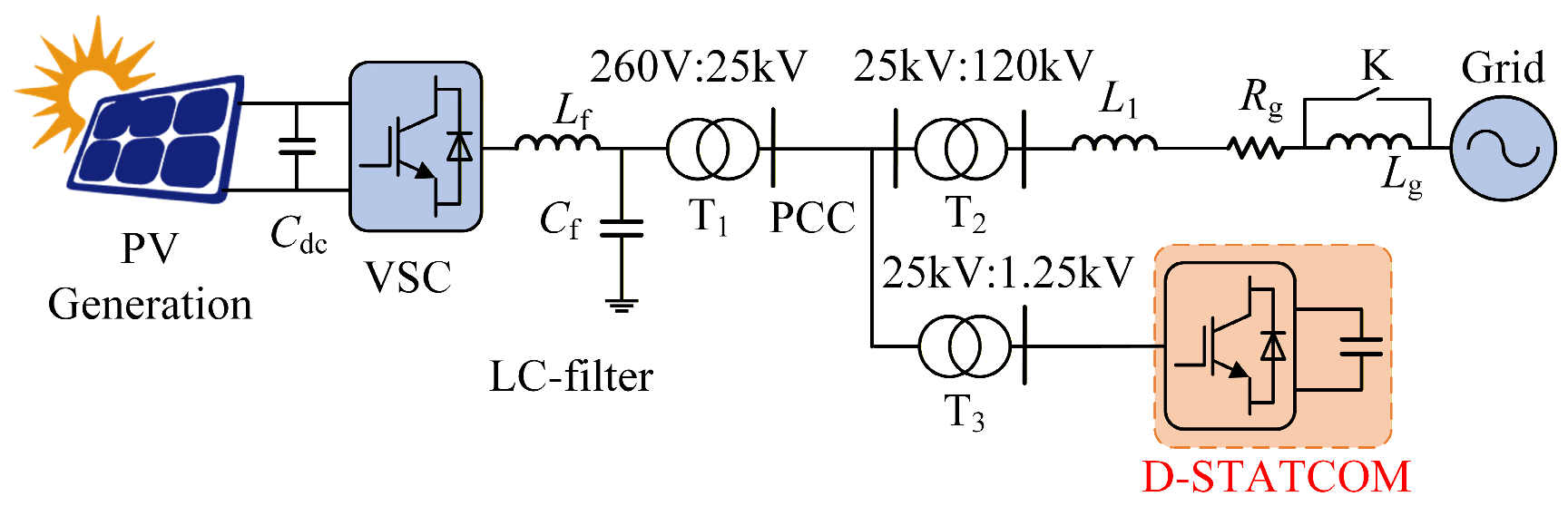
At present, large-scale photovoltaic power plants in the world are far away from the load center and need to transmit active power through long transmission lines. The large transmission line impedance leads to low system strength, which can easily cause SSO accidents. Figure 1 illustrates a simplified but typical equivalent model of a grid-connected PV system. In this paper, the PV farm consists of 20 identically structured PV arrays of 0.5 MW with a capacity of 10 MW.
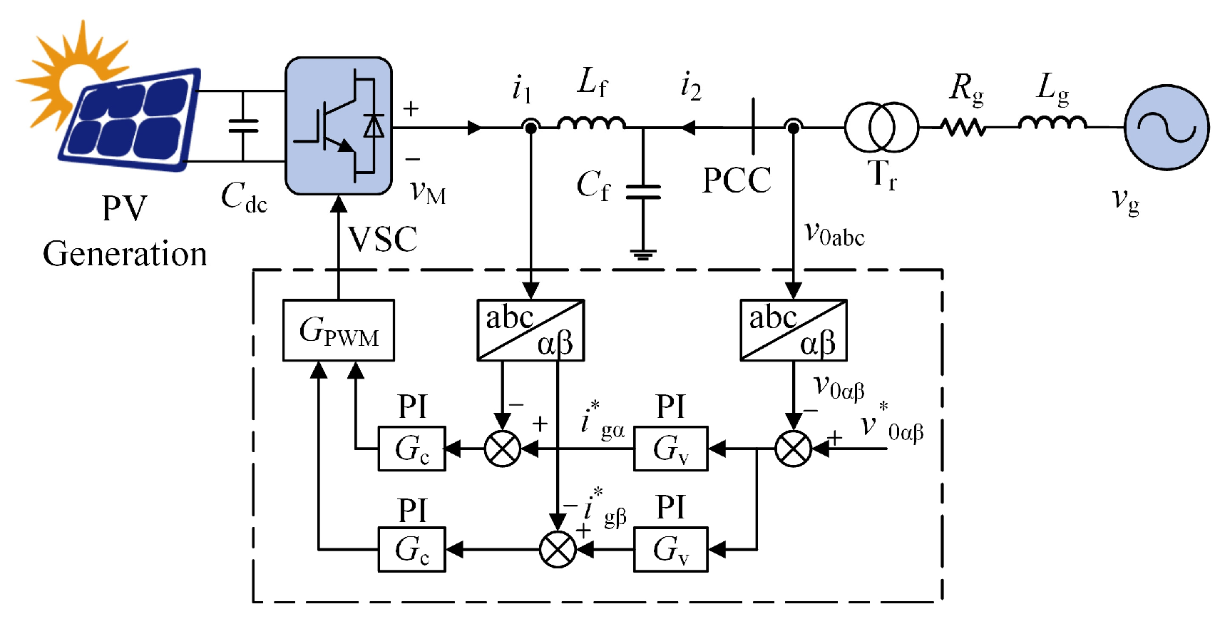
The control block diagram in the αβ coordinate system of the PV converter is depicted in Figure 2. The abc-αβ transformation can decouple the three-phase system into two independent single-phase systems. The AC side current i1 of VSC and the voltage v0 of PCC are decoupled by abc-αβ transformation for analysis.
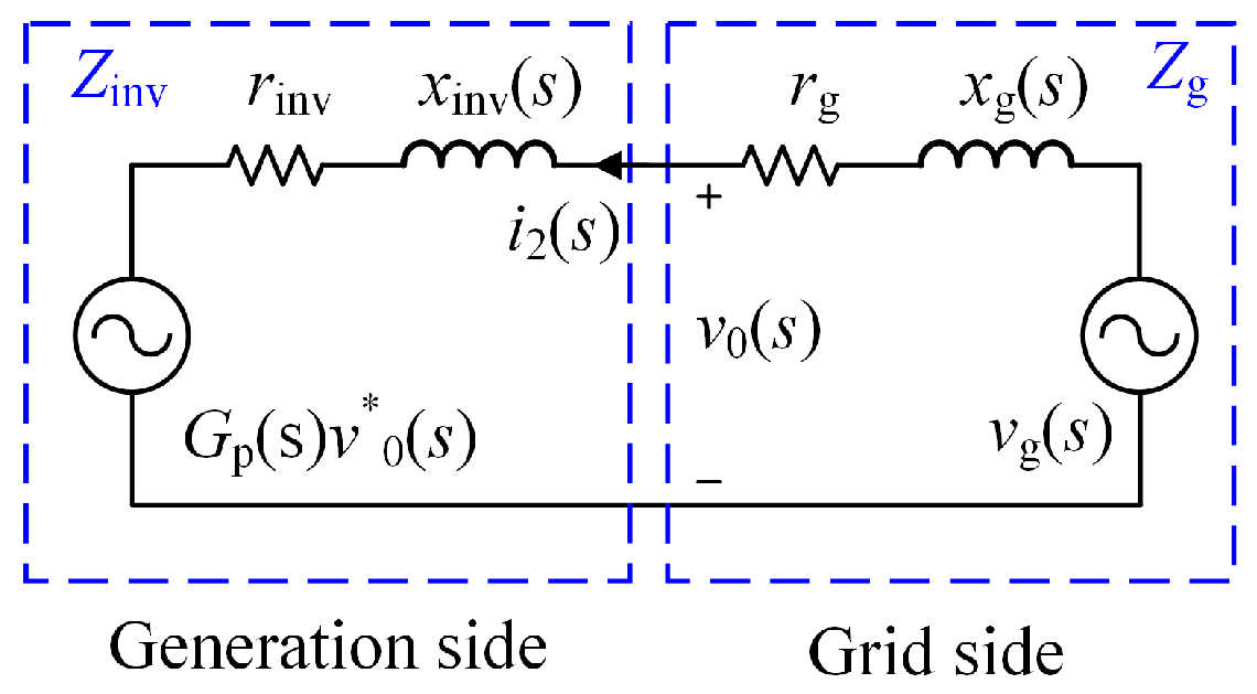
To illuminate the mechanism of the occurrence of sub- or super-synchronous oscillations in the PV system, the established PV system equivalent impedance model is depicted in Figure 3 [36].
Gp(s) is the voltage source converter (VSC) control loop transfer function. From Figure 3, the equivalent impedances on the grid side and the generation side are given as follows:
Z inv s = r inv s + x inv s
Z g s = r g s + x g s .
In Figure 2, the ratio relationship between converter AC side voltage vM, grid-side current i2, and filter current i1 can be formulated as follows:
Y M ( s ) = i 1 ( s ) v M ( s ) = 1 Z L ( s ) + Z C ( s )
G i ( s ) = i 1 ( s ) i 2 ( s ) = Z C ( s ) Z C ( s ) + Z L ( s ) .
Considering the total time delay Td, Gd represents the influence of the total time delay on the control loop. ZL(s) and ZC(s) are the inductive and capacitive impedances of the LC filter, and ZL(s) = sLf, ZC(s) = 1/(sCf).
The transfer functions of Gv, Gc, and Gd are given as:
G v ( s ) = K pv + K iv s G c ( s ) = K pi + K ii s G d ( s ) = e T d s × 1 T d s + 1 .
Suppose  i 1 * = 0  and  i 2 = 0 , respectively. The dynamic characteristics of i1 can be obtained from the superposition theorem:
i 1 ( s ) = T c ( s ) i 1 * ( s ) 1 + T c ( s ) + G i ( s ) i 2 ( s ) 1 + T c ( s )
where Tc(s) is the open-loop gain of the current control loop:
T c ( s ) = G c ( s ) G d ( s ) Y M ( s ) .
According to the loop voltage theorem, the PCC voltage v0 in Figure 3 can be expressed as:
v 0 ( s ) = G p ( s ) v 0 * ( s ) + Z inv ( s ) i 2 ( s )
where Gp(s) is the transfer function of the voltage control loop, which can be regarded as constant when the performance of the inverter is excellent. v*0(s) is the voltage loop reference value, and it is a stable value. i2 is the grid side current, and Zinv is the converter side impedance. When integrated into the large power grid, the vg(s) is a stable value. i2(s) is only associated with the grid-side impedance Zg(s). Under weak grid conditions, the impedance of the grid side is approximately Zg(s) = sLg:
i 2 ( s ) = n 1 n 2 × v g ( s ) s L g 1 Z g ( s ) .
In (8), Gp(s) and Zinv(s) can be expressed as:
G p ( s ) = T v ( s ) 1 + T v ( s ) Z inv ( s ) = Z op ( s ) 1 + T v ( s ) .
where Tv(s) is the open-loop gain of the control system:
T v ( s ) = T c ( s ) 1 + T c ( s ) G v ( s ) Z C ( s ) = G c ( s ) G d ( s ) G v ( s ) Z C ( s ) Z L ( s ) + Z C ( s ) + G c ( s ) G d ( s ) .
Let i*1(s) = 0. Equation (6) can be expressed as:
i 1 ( s ) = G i ( s ) i 2 ( s ) 1 + T c ( s ) .
According to Figure 2, the relationship between v0, i1 and i2 is denoted as:
v 0 = ( i 2 i 1 ) Z C .
According to (12) and (13), the Zop(s) can be expressed as:
Z op ( s ) = v 0 ( s ) i 2 ( s ) = Z C ( s ) 1 G i ( s ) 1 + T c ( s ) = Z C ( s ) Z L ( s ) + G c ( s ) G d ( s ) Z C ( s ) + Z L ( s ) + G c ( s ) G d ( s ) .
According to (10), (11), and (14), the Zinv(s) can be expressed as:
Z inv ( s ) = G c ( s ) G d ( s ) Z C ( s ) + Z C ( s ) Z L ( s ) Z L ( s ) + Z C ( s ) + G c ( s ) G d ( s ) ( 1 + G v ( s ) G c ( s ) )
Therefore, the total system impedance Ztotal(s) is expressed as:
Z total ( s ) = Z inv ( s ) + Z g ( s ) = G c ( s ) G d ( s ) Z C ( s ) + Z C ( s ) Z L ( s ) Z L ( s ) + Z C ( s ) + G c ( s ) G d ( s ) ( 1 + G v ( s ) G c ( s ) ) + s L g .
The admittance of the system is given as:
Y total ( s ) = 1 Z total ( s ) .
Let s = jω. The real part of the global admittance (Re (Ytotal)) can be obtained by rationalizing Equation (17), and ωsub = 2πfsub, ωsup = 2πfsup. According to the global admittance criterion (GA) in the impedance analysis method [37,38], under the sub- or super-synchronous frequency, the PV grid-connected system will exhibit the SSO phenomenon when the real part of the system admittance at the electrical resonance point is less than zero (Re (Ytotal) < 0).

2.2. Principle of D-STATCOM Mitigating SSO

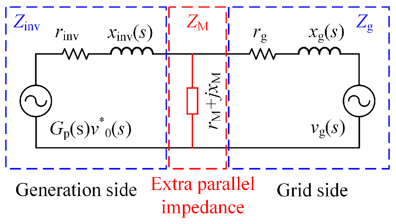
Through the impedance model analysis of the PV system integrated to a weak AC grid, it can be observed that there is a threat of SSO occurring when the damping of the system is negative. The D-STATCOM can be equivalent to a variable impedance, which can reshape the PV system’s impedance characteristics. The supplementary damping control will enhance the damping of the system at sub- or super-synchronous frequency. The equivalent impedance of the D-STATCOM with supplementary damping control in the transmission line is given in Figure 4.
The D-STATCOM equivalent impedance ZM(s) is paralleled in the transmission line.
Z M ( s ) = r M + j x M .
Therefore, the total system equivalent impedance will be:
Z TOTAL = Z inv ( s ) Z M ( s ) Z g ( s ) Z inv ( s ) Z M ( s ) + Z inv ( s ) Z g ( s ) + Z M ( s ) Z g ( s ) .
The basic principle of D-STATCOM to suppress SSO is to extract the sub- or super-synchronous current from the point of common coupling (PCC). And through the supplementary damping control strategy and sinusoidal pulse width modulation (SPWM) strategy, the D-STATCOM generates the sub- or super-synchronous voltage with the same phase as the sub- or super-synchronous current. At this point, the D-STATCOM can be equivalent to the positive damping of the transmission line connected in parallel.

3. Control Strategy of D-STATCOM Mitigating SSO

3.1. Whole Control Strategy

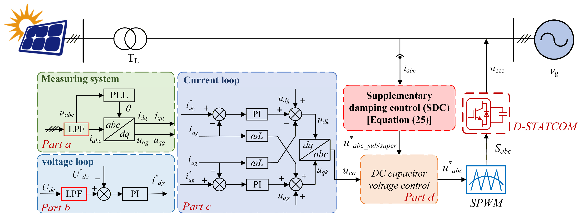
The basic control and supplementary damping control make up the whole control strategy, as Figure 5 shows. As depicted in Figure 5, the basic control consists of 4 parts (a, b, c, and d). Part a consists of two measurement systems. The abc-dq transformation is performed on the synchronous reference provided by PLL to compute the d-axis and q-axis components of the current and voltage. Part b represents DC voltage control. Udc is DC mean capacitor voltage, and U*dc is its reference value. The functional block PI controller regulates the difference between Udc and U*dc to output the d-axis reference current i*dg. The LPF in parts a and b is a second-order Butterworth low-pass filter, whose role is to filter out high-frequency harmonics and improve the control system performance.
Part c shows an inner current regulation loop, which includes two PI controllers which adjust the currents of q-axis and d-axis. The output udk and uqk of the controller are converted into phase voltages ua, ub, and uc, which are used to synthesize the PWM voltages. The i*qg is generated by the outer voltage regulation loop, and i*dg is the output of DC voltage control. The function of part d is to receive the damping signal generated by the supplementary damping control and the command signal generated by part c, and then generate the final modulation command of the D-STATCOM converter. The input signal of the SDC strategy is the transmission line current, and the output signal u*abc_sub/super is the sub synchronous/super synchronous voltage command value to suppress the SSO. u*abc is the modulation command value that superimposes the command value u*abc_sub/super to suppress the SSO and the interphase voltage balancing command value uca of D-STATCOM itself, which forms the converter modulation signal through the SPWM block. In the normal operation of the system, the transmission line does not contain sub-synchronous/super-synchronous current components, so the SDC does not work, and the D-STATCOM only acts as voltage support and reactive power compensation. D-STATCOM supplementary damping control serves as an additional layer to provide positive damping for the system to suppress SSO without affecting the original control objectives of the system, such as voltage regulation and power balance. When the PV plant is incorporated into the weak grid, D-STATCOM compensates for the reactive power of the system.

3.2. Supplementary Damping Control Strategy

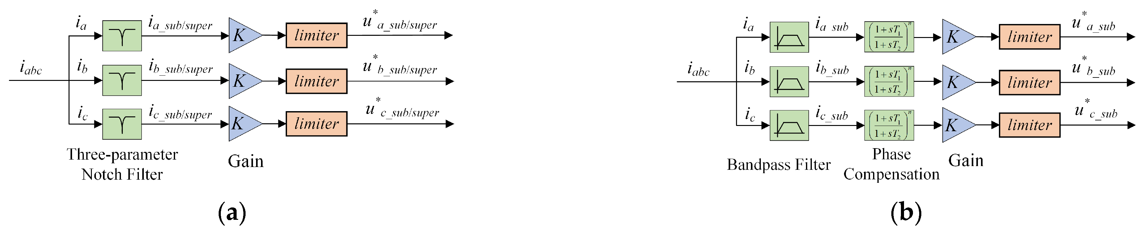
The supplementary damping controller generates the sub- or super-synchronous voltage reference signal in the same phase based on the sub- or super-synchronous current component in the feedback signal of the line current, and its structure is shown in Figure 6. The conventional SDC uses band-pass filters to extract sub-synchronous/super-synchronous current components in transmission lines. The use of a bandpass filter results in a phase offset of the extracted sub- or super-synchronous current components, so a phase compensation link is required to compensate for the phase of the extracted components. Therefore, the structure and parameter design of SDC will become very complex. To simplify the structure of SDC and avoid the complexity of parameter design, a three-parameter notch filter is proposed to replace the band-pass filter composed of a band-stop filter and a low-pass filter in traditional SDC, and the phase compensation is eliminated, so that the structure of SDC is greatly optimized and the parameter design is simplified. Table 1 presents a quantitative comparison with conventional SDC. Compared with the traditional SDC, the notch filter designed in this paper can meet the requirements and has better applicability. It is easier to implement because of its simplified structure and parameter design.
The proposed SDC structure is shown in Figure 6a, which mainly includes a three-parameter notch filter and a gain link. The sub-synchronous/super-synchronous current signal without phase offset in the transmission line is extracted by the three-parameter notch filter. After the sub- or super-synchronous current signal passes through the gain K and the limiter, the reference command u*abc_sub/super for D-STATCOM to suppress SSO is obtained. After the command is superimposed on the main modulation wave of the DC capacitor voltage controller of D-STATCOM, it can output uabc_sub/super with the same phase as iabc_sub/super. At this time, D-STATCOM is equivalent to the positive resistance at the sub-synchronous frequency, which provides positive damping for the entire photovoltaic system and achieves the purpose of suppressing SSO.
To further highlight the superiority of the proposed solution, Table 2 provides a quantitative comparison with existing solutions. Based on existing research, recovery time is determined by the variation in active power.

3.3. Design of Supplementary Damping Control Parameters

The three-parameter notch filter can quickly attenuate the input signal at a certain frequency to achieve the filtering effect of blocking the signal at that frequency. Therefore, the sub- or super-synchronous current components can be obtained by filtering the fundamental frequency signal of the current in the transmission line. The transfer function is given as [40,41]:
G ( s ) = s 2 + 2 ξ 2 ω n s + ω n 2 s 2 + 2 ξ 1 ω n s + ω n 2
where ωn is the center frequency of the notch, and ξ1 and ξ2 are notch factors. The mathematical relationship between these two factors is as follows:
ξ 1 = 1 1 + B 2 ω n 2 4 d e p t h 2 2
d e p t h = ξ 2 ξ 1
B = 2 π f ω b .
The parameter depth means notch depth. To completely filter out the fundamental frequency components, the ωn is set to 60 Hz, and the notch depth is set to 0.01. This depth value is determined to ensure that the target signal can be effectively filtered out. Considering the fluctuation of the oscillation frequency of the PV system, the dynamic response performance of the filter directly affects the extraction accuracy of the sub-synchronous/super-synchronous current in the line. To ensure that the oscillation component can be extracted in any case and balance performance and robustness, the bandwidth fωb is set to 0.5 Hz. At last, the design of the notch filter is as follows:
G E ( s ) = s 2 + 0.03142 s + 142,100 s 2 + 3.142 s + 142,100 .
The mitigation performance of the supplementary damping control on the SSO is not only related to the selection of the filter but also to the gain K. In general, the larger the value of K, the larger the positive damping provided by D-STATCOM for the system. However, if the value of gain K is too large, it not only needs to adjust the capacity of the converter, increases the engineering manufacturing cost, but also makes the output of the controller easier to reach the limit value. As a result, it is necessary to adjust the value of gain K to match the capacity of D-STATCOM. After the gain block, a limiter is added to limit the amplitude of the SDC output signal within a reasonable range. The parameters of D-STATCOM are shown in Table 3.
The actual operating condition of the system is variable, and the oscillation varies under different conditions. Increasing K can enhance the equivalent positive damping and the oscillation suppression effect, but it will also lead to excessive fluctuations in the dynamic response. Therefore, this article conducts many simulation tests to select the minimum K value that can achieve the suppression effect as the final set value [35].
Taking all the parts into account, the SDC transfer function is given as:
G SDC ( s ) = G E ( s ) × K
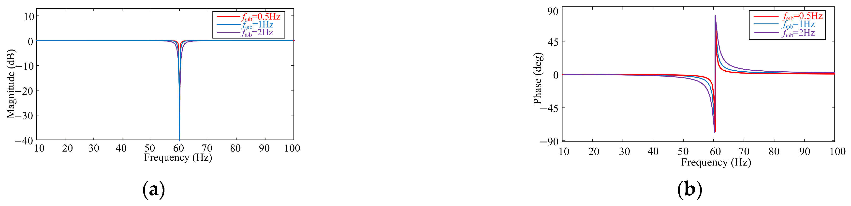
The Bode plot of the three-parameter notch filter is shown in Figure 7. The notch bandwidth of the notch filter is narrow enough so that the designed filter can still filter the fundamental frequency signal and extract the sub- or super-synchronous current from the line, even if the system condition changes and the oscillation frequency shifts. From Figure 7b, the three-parameter notch filter introduces minimal phase shift within the sub-synchronous oscillation frequency band of the target and can be regarded as having a negligible phase shift. Therefore, no additional phase compensation circuit is required.

4. Simulation Results

4.1. Simulation Model of the PV Grid-Connected System

To prove the validity of the proposed supplementary damping control strategy, an equivalent PV system model as depicted in Figure 1 is established in MATLAB R2024a/Simulink [42,43]. As shown in Figure 1, the series inductance Lg is used to simulate the change of the system strength after the PV is integrated into the grid. The strength of the system is mainly characterized by the short-circuit ratio (SCR), which is described in Equation (26)
SCR = S ac S N = v g 2 Z g S N
where SN is the nominal power of the PV plant; Sac is the system short-circuit capacity. vg is the grid voltage, and Zg is the impedance of the grid. Since the grid inductance is much larger than the grid resistance, the grid resistance is ignored in the calculation of the SCR. The value of the grid inductance is changed during simulation to simulate the change of the system SCR.
In the initial conditions of the simulation, the PV array’s initial input irradiance is 1000 W/m2, and the operating temperature is 25 degrees C, which means the model is operating at the maximum power point. The parameters of the controllers and circuits in Figure 1 are given in Table 4.
Ug represents the voltage level of the power grid. The parameters XT1 and XT2 are the reactance of transformers, and kiv and kpv are the integral and proportional coefficients of the outer voltage regulator loop. kii and kpi are the integral and proportional coefficients of the inner current regulator loop. kLp and kLi represent the proportional-integral coefficients of the PLL.

4.2. Effectiveness of the SDC

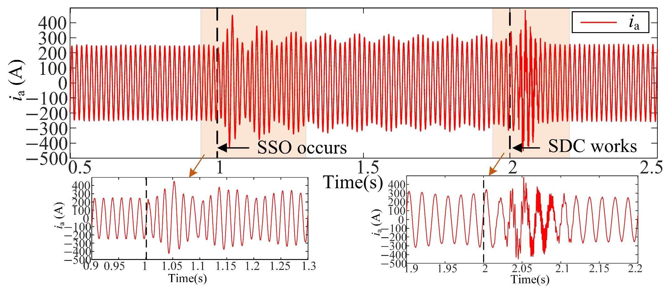
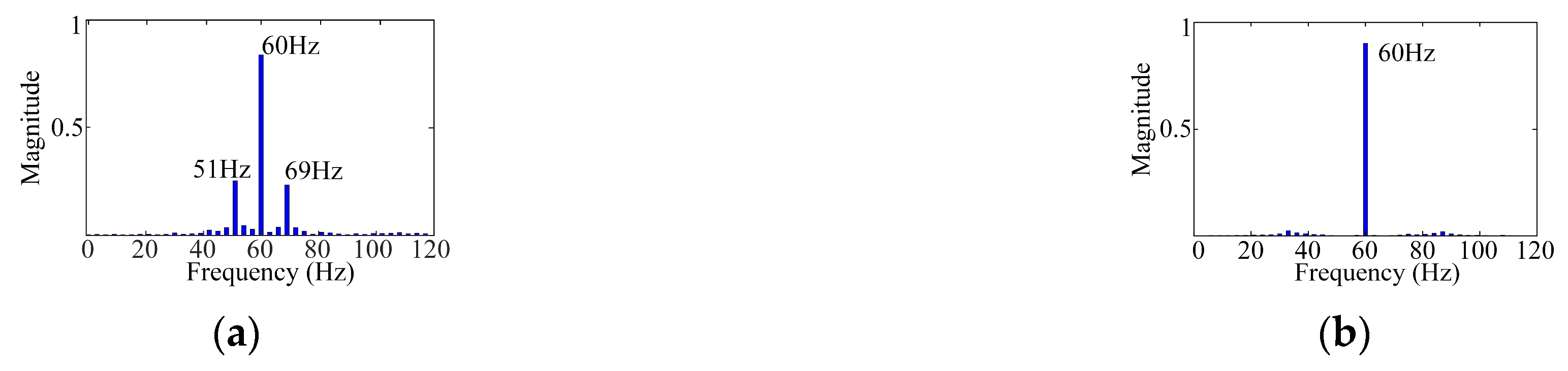
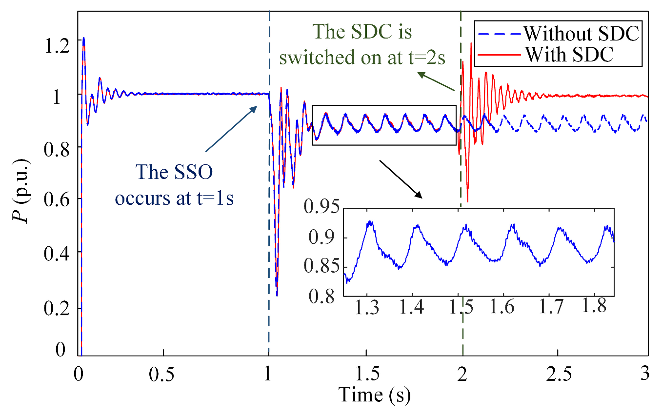
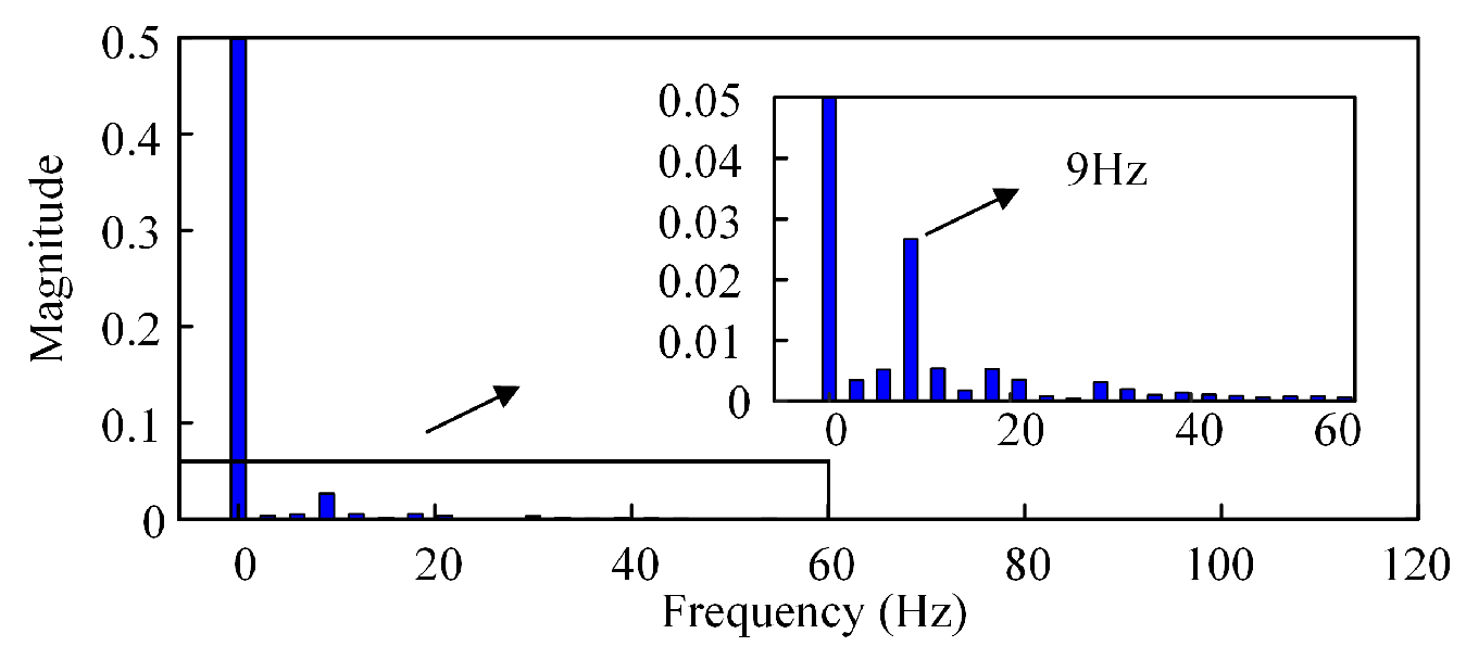
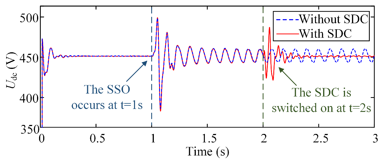
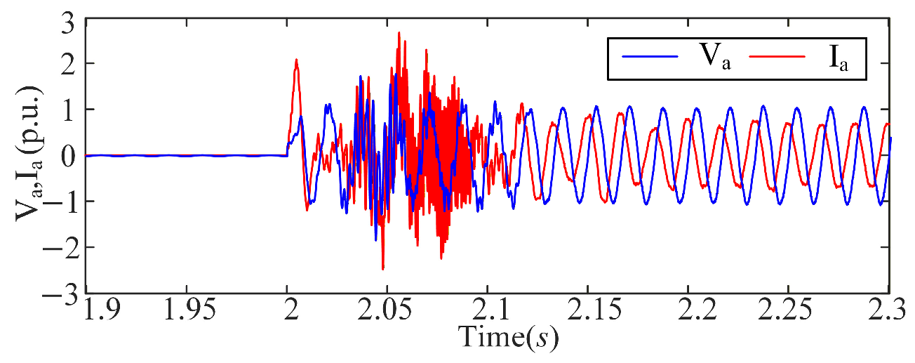
The performance of the SDC to alleviate the SSO is demonstrated in the simulation of the case scenario. In the beginning, the system works in a normal state when the series inductor Lg is short-circuited. When the inductor Lg is turned on at t = 1 s, the system stiffness is reduced, and it operates under a weak grid condition. At this point, SCR is 1.4, and the SSO is triggered. Figure 8 shows the waveform of the three-phase current variations. After the system was integrated into the weak grid, there was a growing SSO appearing in the current of the transmission line. At t = 2 s, the SDC is put into operation, and the SSO is mitigated quickly. From the FFT analysis of the current, it can be observed that there are two oscillation frequencies which are distributed on both sides of the fundamental frequency. One is about 51 Hz, and the other is 69 Hz, as observed in Figure 9a. The SDC is put into operation at t = 2 s, and the sub- or super-synchronous harmonic components are significantly alleviated, as depicted in Figure 9b. Meanwhile, Figure 10 shows the active power variation waveform of PCC. When the system is connected to the weak grid, its active power experiences oscillations, and the FFT analysis indicates that the oscillation frequency is 9 Hz, as shown in Figure 11. However, at t = 2 s, after the proposed SDC is connected, the power oscillations are effectively suppressed. Moreover, when the inductor Lg is connected in series, the transmission capacity of active power decreases. Figure 12 displays the DC voltage of the PV generation. Figure 13 displays the output waveform of D-STATCOM. When the D-STATCOM supplementary damping control was initially activated, due to the large sub-synchronous current component in the system, the actual output voltage of the D-STATCOM reached the rated value of the device. Approximately 0.1 s later, the oscillation was suppressed, and the system became stable, with only the fundamental frequency components present in the output voltage and current. The proposed scheme effectively suppressed the SSO, thereby verifying that the proposed scheme can achieve a good suppression effect.
When the SSO is suppressed, the output of D-STATCOM contains only the fundamental frequency component.
The base case scenario simulation results can be demonstrated by analyzing the system impedance model with the global admittance criterion. To obtain the impedance characteristics of the D-STATCOM, harmonic voltages with a small amplitude are injected sequentially at the PCC of the PV system. Thus, the impedance of the harmonic voltage frequency range is obtained through the frequency sweep method. The frequency of small voltage injections was 45 Hz to 55 Hz and 65 Hz to 75 Hz with 1 Hz intervals. The RX curves from 46 Hz to 52 Hz and 66 Hz to 72 Hz are displayed in Figure 14. It can be observed that the D-STATCOM can supply adequate positive damping to the system at sub- or super-synchronous frequency to mitigate oscillation.

4.3. Robustness of the SDC

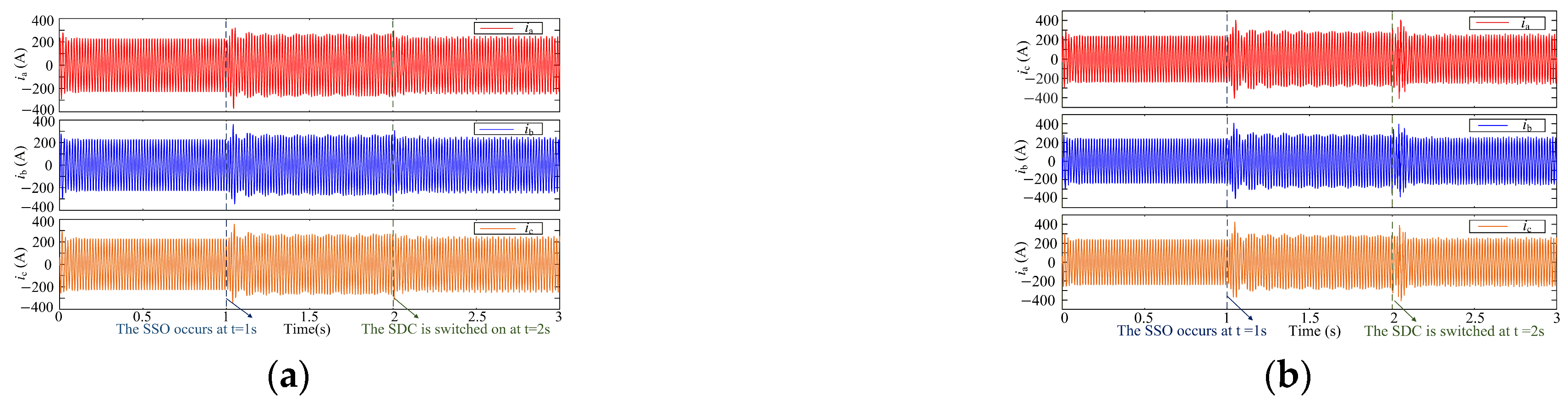
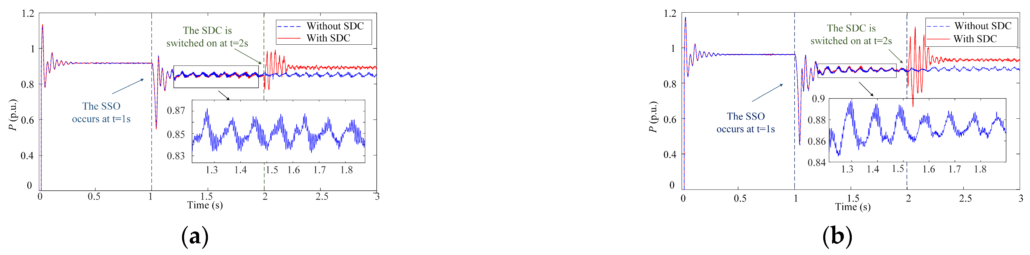
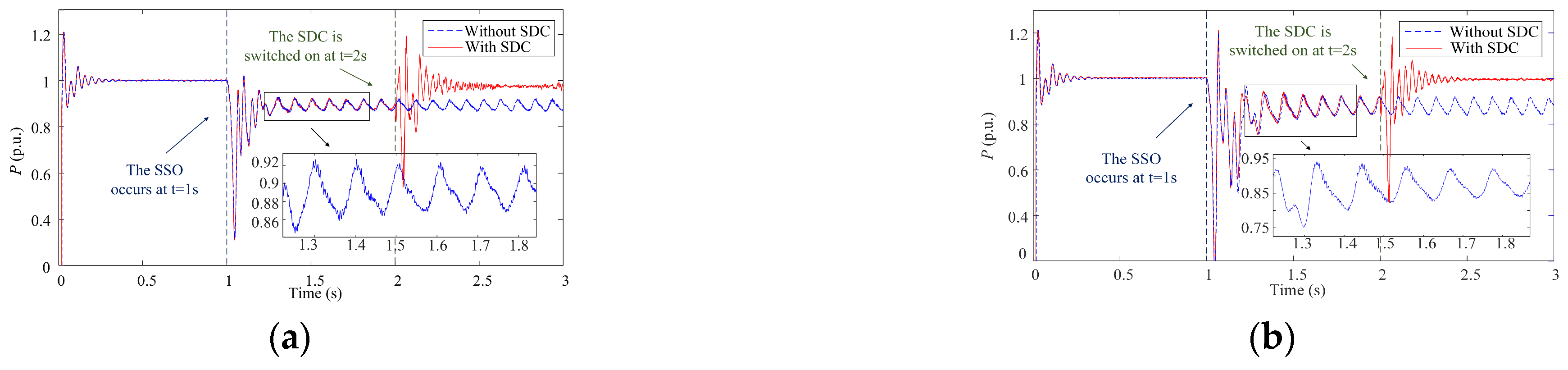
It is considered that a PV plant presents the characteristics of intermittency and volatility. To prove the robustness of the presented method under various input irradiances, an extension is made based on the simulated basic scenario. Keeping the remaining parameters the same, the input irradiances of the simulation are set to 950 W/m2 and 900 W/m2. At t = 1 s, the system undergoes SSO, and at t = 2 s, the SDC is put into operation. The transmission line current waveform is depicted in Figure 15. When the series inductor Lg is turned on, the active power at the point of common coupling of the PV generation integrated to the weak AC grid will be unstable and oscillate. After that, when the SDC of D-STATCOM is put into use at t = 2 s, the active power oscillation is suppressed. Figure 16 compares the active power change waveform of the PCC before and after the SDC is put into operation. The DC link voltage waveform of PV generation is displayed in Figure 17.
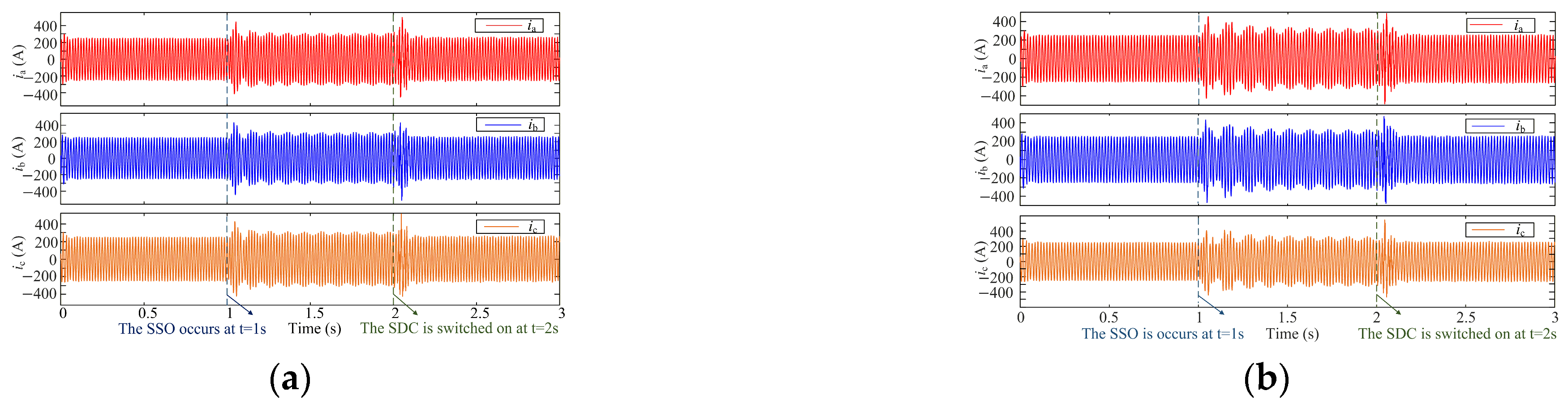
The PV grid-tied system stability under weak grid conditions is seriously affected by grid impedance. The simulation of the base case scenario is set as SCR = 1.415 and SCR = 1.385, while the other parameters remain the same. While the series inductance Lg is switched on at t = 1 s, the system experiences serious oscillation and loses stability. As the series inductance Lg increases, the system strength becomes weaker, and the oscillation amplitude of the system becomes larger. When the SDC is switched on and begins to take effect at t = 2 s, as the oscillations of the system converge, the system stability begins to recover. Figure 18 illustrates the transmission line current. The active power of PCC is demonstrated in Figure 19. Figure 20 displays the DC link voltage waveform of PV generation. Figure 21 displays the DC link voltage and the active power waveform at SCR = 1.4. At t = 2.5 s, the input irradiance is reduced from 1000 W/m2 to 900 W/m2. It is obvious that the proposed control strategy still has a good effect when the external environment changes. System faults seriously affect the safety and stability of power systems. It is necessary to test the anti-interference capability of the proposed scheme under fault conditions. Figure 22 shows the results of the DC voltage of PV generation and the active power of PCC under a single-phase fault at SCR = 1.4. At t = 3 s, a single-phase fault occurs in the system. The proposed control strategy can significantly enhance the stability of the system in case of faults.

5. Conclusions

By establishing the impedance model of a PV system, this article investigates the mechanism of SSO between a PV farm and a weak grid through the global admittance criterion (GA). Then, a new SDC for D-STATCOM is presented to mitigate SSO in PV generation integrated to a weak grid. The SDC uses a three-parameter notch filter and a gain block to generate oscillating damping control signals. The SDC presented in this article can accurately eliminate fundamental frequency and track the sub- or super-synchronous frequency under various operating conditions. Due to its characteristic of being frequency-based and insensitive to model parameters, it can also be applied to the suppression of SSO in wind power systems. The conclusions are summarized below:
(1)
The D-STATCOM supplementary damping control can offer sufficient positive damping within the sub- or super-synchronous frequencies. Moreover, the D-STATCOM effectively compensates for the reactive power of the weak grid and enhances the system’s active power transmission capacity. The results of time domain simulation under various operating states prove the validity and robustness of the presented strategy.
(2)
In contrast to existing SDC [25], the proposed SDC can adapt well to various complicated operating conditions and simplify the calculation process. It can make up for the defects of the bandpass filter phase shift, and the response time is shorter. The recovery time is shortened from more than 1 s to about 0.3 s. The supplementary damping control also has the advantages of convenient parameter tuning and easy implementation.
(3)
However, the value of gain K in the proposed SDC in this paper is the minimum value that can suppress the SSO under the most severe working conditions, which is the fixed value. The subsequent research direction can study the adaptive ability of the proposed suppression strategy by reasonably selecting the gain K based on the oscillation situation of the system.

Author Contributions

Methodology and software, Q.C.; validation and formal analysis, N.W.; investigation and resources, Z.W.; data curation, writing—original draft, Z.A.; writing—review and editing, P.T.; supervision and project administration, Y.L. All authors have read and agreed to the published version of the manuscript.

Funding

This work was supported by the technological projects of the State Grid Economic and Technological Research Institute Co., Ltd. (No. SGJY0000SDJS2500490).

Data Availability Statement

The original contributions presented in this study are included in the article. Further inquiries can be directed to the corresponding author.

Conflicts of Interest

Authors Qichao Chen, Nan Wei, Zhidong Wang and Zhi An were employed by the company of State Grid Economic and Technological Research Institute. The remaining authors declare that the research was conducted in the absence of any commercial or financial relationships that could be construed as a potential conflict of interest.

Nomenclature

The following nomenclature is used in this manuscript:
RgThe equivalent grid resistance
LgThe equivalent grid inductance
vMThe voltage of converter AC side
v0The voltage of PCC
v*0(s)The voltage loop reference value
v0(s)The voltage of PCC
vg(s)The grid voltage
xinv(s)The generation side equivalent inductance
rinv(s)The generation side equivalent resistance.
xg(s)The grid side equivalent inductance.
rg(s)The grid side equivalent resistance.
GcThe current loop PI control function.
GvThe voltage loop PI control function.
KivThe integral gain the converter voltage loop
KpvThe proportional gain the converter voltage loop
KiiThe integral gain the converter current loop
KpiThe proportional gain the converter current loop
TdThe time delay constant.
Zop(s)The open-loop input impedance.
n1The Primary winding of the transformer
n2The Secondary winding of the transformer

References

  1. Shao, B.; Xiao, Q.; Meng, X.; Han, P.; Ma, W.; Miao, Z.; Blaabjerg, F.; Chen, Z. Medium-frequency and sub-synchronous oscillation analysis of direct-drive wind farms connected to the parallel-compensated AC grid. Electr. Power Syst. Res. 2023, 216, 109061. [Google Scholar] [CrossRef]
  2. Leon, A.E.; Amodeo, S.J.; Mauricio, J.M. Enhanced Compensation Filter to Mitigate Subsynchronous Oscillations in Series-Compensated DFIG-Based Wind Farms. IEEE Trans. Power Deliv. 2021, 36, 3805–3814. [Google Scholar] [CrossRef]
  3. Cheng, Y.; Fan, L.; Rose, J.; Huang, S.-H.; Schmall, J.; Wang, X.; Xie, X.; Shair, J.; Ramamurthy, J.R.; Modi, N.; et al. Real-World Subsynchronous Oscillation Events in Power Grids with High Penetrations of Inverter-Based Resources. IEEE Trans. Power Syst. 2023, 38, 316–330. [Google Scholar] [CrossRef]
  4. Li, C. Unstable Operation of Photovoltaic Inverter from Field Experiences. IEEE Trans. Power Deliv. 2018, 33, 1013–1015. [Google Scholar] [CrossRef]
  5. Liu, Y.; Tao, P.; Wu, Y.; Yin, L. The DSOGI-PLL with the repetitive control internal model suppresses the SSO in the PV system. Sol. Energy 2025, 296, 113579. [Google Scholar] [CrossRef]
  6. Wang, S.; Li, Y.; Zhang, M.; Peng, Y.; Tian, Y.; Lin, G.; Chang, F. Harmonic Resonance Suppression with Inductive Power Filtering Method: Case Study of Large-Scale Photovoltaic Plant in China. IEEE Trans. Power Electron. 2023, 38, 6444–6454. [Google Scholar] [CrossRef]
  7. Liu, Q.; Liu, F.; Zou, R.; Li, Y. Harmonic Resonance Characteristic of Large-Scale PV Plant: Modelling, Analysis, and Engineering Case. IEEE Trans. Power Deliv. 2022, 37, 2359–2368. [Google Scholar] [CrossRef]
  8. Lofgren, I.; Lennerhag, O. Analysis and mitigation of SSCI when integrating wind power to series compensated lines. Electr. Power Syst. Res. 2023, 223, 109623. [Google Scholar] [CrossRef]
  9. Xue, T.; Karaagac, U.; Xue, H.; Mahseredjian, J. Re-examination of Weak Grid-Connected Voltage Source Converter Instability. Electr. Power Syst. Res. 2023, 223, 109625. [Google Scholar] [CrossRef]
  10. He, Y.; Du, W.; Fu, Q.; Wang, H. Measurement-Driven Damping Control Based on the Deep Transfer Reinforcement Learning to Suppress Sub-synchronous Oscillations in a Large-Scale Renewable Power System. IEEE Trans. Power Syst. 2024, 39, 6649–6661. [Google Scholar] [CrossRef]
  11. Al Jowder, F. Damping of SSR Oscillations of Series Compensated Power System Connected to Two-Stage P-V Controlled PV Power Plant. IEEE Trans. Ind. Appl. 2024, 60, 7623–7633. [Google Scholar] [CrossRef]
  12. Yang, Z.; Shah, C.; Chen, T.; Yu, L.; Joebges, P.; De Doncker, R.W. Stability Investigation of Three-Phase Grid-Tied PV Inverter Systems Using Impedance Models. IEEE J. Emerg. Sel. Top. Power Electron. 2022, 10, 2672–2684. [Google Scholar] [CrossRef]
  13. Chen, Q.; Tang, Y.; Gong, D.; Lin, L.; Zeng, Q.; Shi, X. Analysis and Enhancement of Synchronization Stability in Grid-forming PV Systems Using Torque Component Quantification. IEEE Trans. Energy Convers. 2025, 40, 2227–2241. [Google Scholar] [CrossRef]
  14. Lin, X.; Wen, Y.; Yu, R.; Yu, J.; Wen, H. Improved Weak Grids Synchronization Unit for Passivity Enhancement of Grid-Connected Inverter. IEEE J. Emerg. Sel. Top. Power Electron. 2022, 10, 7084–7097. [Google Scholar] [CrossRef]
  15. Wu, Y.; Wu, H.; Zhao, F.; Li, Z.; Wang, X. Influence of PLL on Stability of Interconnected Grid-Forming and Grid-Following Converters. IEEE Trans. Power Electron. 2024, 39, 11980–11985. [Google Scholar] [CrossRef]
  16. Li, G.; Tang, G.; Liu, X. A Quasi-Harmonic Voltage Compensation Control of PV Grid-Connected Converter for Suppressing Sub/Super-Synchronous Oscillation in Weak Grid. IEEE J. Emerg. Sel. Top. Power Electron. 2024, 12, 4144–4153. [Google Scholar] [CrossRef]
  17. Jia, Q.; Yan, G.; Cai, Y.; Li, Y.; Zhang, J. Small-signal stability analysis of photovoltaic generation connected to weak AC grid. J. Mod. Power Syst. Clean Energy 2019, 7, 254–267. [Google Scholar] [CrossRef]
  18. Song, S.; Wei, Z.; Lin, Y.; Liu, B.; Liu, H. Impedance modeling and stability analysis of PV grid-connected inverter systems considering frequency coupling. CSEE J. Power Energy Syst. 2020, 6, 279–290. [Google Scholar] [CrossRef]
  19. Yan, G.; Wang, Z.; Zhao, Y.; Wang, Y.; Peng, J.; Wang, D. Analysis and Suppression of Sub-Synchronous Oscillation of Photovoltaic Power Generation Based on Damping Torque Method. IEEE Trans. Ind. Appl. 2024, 60, 5074–5083. [Google Scholar] [CrossRef]
  20. Dong, J.; Liang, J.; Li, X.; Rong, S.; Gao, B.; Cui, T. Analysis of Sub-synchronous Oscillation Disturbance Path and Damping Characteristics of Photovoltaic Incorporated into Weak AC Power Grid. In Proceedings of the 2022 China International Conference on Electricity Distribution (CICED), Changsha, China, 7–8 September 2022; pp. 1349–1354. [Google Scholar]
  21. Xu, J.; Zhong, J.; Kang, J.; Dong, W.; Xie, S. Stability Analysis and Robust Parameter Design of DC-Voltage Loop for Three-Phase Grid-Connected PV Inverter Under Weak Grid Condition. IEEE Trans. Ind. Electron. 2024, 71, 3776–3787. [Google Scholar] [CrossRef]
  22. Touti, E.; Abdeen, M.; El-Dabah, M.A.; Kraiem, H.; Agwa, A.M.; Alanazi, A.; Alanazi, T.I. Sub-Synchronous Oscillation Mitigation for Series-Compensated DFIG-Based Wind Farm Using Resonant Controller. IEEE Access 2024, 12, 66185–66195. [Google Scholar] [CrossRef]
  23. Inomoto, R.S.; Monteiro, J.R.B.d.A.; Filho, A.J.S. Boost Converter Control of PV System Using Sliding Mode Control with Integrative Sliding Surface. IEEE J. Emerg. Sel. Top. Power Electron. 2022, 10, 5522–5530. [Google Scholar] [CrossRef]
  24. Sangwongwanich, A.; Blaabjerg, F. Mitigation of Interharmonics in PV Systems with Maximum Power Point Tracking Modification. IEEE Trans. Power Electron. 2019, 34, 8279–8282. [Google Scholar] [CrossRef]
  25. Alturki, F.A.; Omotoso, H.O.; Al-Shamma’a, A.A.; Farh, H.M.H.; Alsharabi, K. Novel Manta Rays Foraging Optimization Algorithm Based Optimal Control for Grid-Connected PV Energy System. IEEE Access 2020, 8, 187276–187290. [Google Scholar] [CrossRef]
  26. Shair, J.; Xie, X.; Yang, J.; Li, J.; Li, H. Adaptive damping control of subsynchronous oscillation in DFIG-based wind farms connected to series-compensated network. IEEE Trans. Power Deliv. 2022, 37, 1036–1049. [Google Scholar] [CrossRef]
  27. Li, G.; Chen, Y.; Luo, A.; Wang, H. An Enhancing Grid Stiffness Control Strategy of STATCOM/BESS for Damping Sub-Synchronous Resonance in Wind Farm Connected to Weak Grid. IEEE Trans. Ind. Inf. 2020, 16, 5835–5845. [Google Scholar] [CrossRef]
  28. Li, Y.; Yi, H.; Zhuo, F.; Jiang, X. Harmonic Oscillation and Stabilization Strategy of Source-Current-Detected Shunt APF Considering Interaction with Nonlinear Load and Grid Impedance. IEEE J. Emerg. Sel. Top. Power Electron. 2024, 12, 420–430. [Google Scholar] [CrossRef]
  29. Li, G.; Chen, Y.; Luo, A.; Liu, X. Wideband Harmonic Voltage Feedforward Control Strategy of STATCOM for Mitigating Subsynchronous Resonance in Wind Farm Connected to Weak Grid and LCC HVDC. IEEE J. Emerg. Sel. Top. Power Electron. 2021, 9, 4546–4557. [Google Scholar] [CrossRef]
  30. Varma, R.K.; Maleki, H. PV Solar System Control as STATCOM (PV-STATCOM) for Power Oscillation Damping. IEEE Trans. Sustain. Energy 2019, 10, 1793–1803. [Google Scholar] [CrossRef]
  31. Yao, J.; Wang, X.; Li, J.; Liu, R.; Zhang, H. Sub-Synchronous Resonance Damping Control for Series-Compensated DFIG-Based Wind Farm with Improved Particle Swarm Optimization Algorithm. IEEE Trans. Energy Convers. 2019, 34, 849–859. [Google Scholar] [CrossRef]
  32. Zhang, X.; Xie, X.; Li, X.; Shair, J.; Liu, C. Supplementary Damping Control of STATCOM to Mitigate SSCI. In Proceedings of the 2019 IEEE Innovative Smart Grid Technologies—Asia (ISGT Asia), Chengdu, China, 21–24 May 2019; pp. 2245–2249. [Google Scholar]
  33. Yarlagadda, V.; Garikapati, A.K.; Gadupudi, L.; Kapoor, R.; Veeresham, K. Comparative Analysis of STATCOM and SVC on Power System Dynamic Response and Stability Margins with time and frequency responses using Modelling. In Proceedings of the 2022 International Conference on Smart Technologies and Systems for Next Generation Computing (ICSTSN), Villupuram, India, 25–26 March 2022; pp. 1–8. [Google Scholar]
  34. Hsieh, S.-C. Economic Evaluation of the Hybrid Enhancing Scheme with DSTATCOM and Active Power Curtailment for PV Penetration in Taipower Distribution Systems. IEEE Trans. Ind. Appl. 2015, 51, 1953–1961. [Google Scholar] [CrossRef]
  35. Gao, B.; Wang, F.; Yu, H.; Zhao, G.; Bingbing, S.; Shuqiang, Z. The Suppression Method of Wind Power Sub-Synchronous Oscillation Using Static Synchronous Series Compensator. Trans. China Electrotech. Soc. 2020, 35, 1346–1356. (In Chinese) [Google Scholar]
  36. Zhu, X.; Hu, H.; Tao, H.; He, Z. The Mechanism and Influence of Harmonic Instability for Photovoltaic Grid-Connected System. Trans. China Electrotech. Soc. 2019, 32, 33–41. (In Chinese) [Google Scholar]
  37. Cao, W.; Wang, S.; Kang, H.; Liu, K.; Wang, Q.; Zhao, J. Inherent Interaction Analysis for Harmonic Oscillations in the Multi-Paralleled Grid-Connected Inverter System Using a Sum Type Criterion: Global Admittance (GA). IEEE Access 2020, 8, 8275–8285. [Google Scholar] [CrossRef]
  38. Sainz, L.; Cheah-Mane, M.; Monjo, L.; Liang, J.; Gomis-Bellmunt, O. Positive-Net-Damping Stability Criterion in Grid-Connected VSC Systems. IEEE J. Emerg. Sel. Top. Power Electron. 2017, 5, 1499–1512. [Google Scholar] [CrossRef]
  39. Zhang, J.; Guo, C.; Xu, L. A Multi-Mode Sub-Synchronous Damping Controller for Renewable-Thermal-Bundled Power Transmission by LCC-HVDC System. IEEE Trans. Sustain. Energy 2025, early access. [Google Scholar] [CrossRef]
  40. Chang, H.; Lu, S.; Zheng, S.; Song, B. Resonance Suppression Based on Improved BFGS Notch Filter and Simplified Linear Triangular Model for Double-Inertia Servo Control. IEEE ASME Trans. Mechatron. 2024, 29, 2150–2160. [Google Scholar] [CrossRef]
  41. Zhang, W.; Xie, S.; Feng, X.; Gu, P.; Lei, Z.; Zhao, C. Research on Harmonic Suppression of OW-PMSM with Common DC Bus for Three-parameter Digital Notch Filter Based on Voltage Compensation. In Proceedings of the 2023 6th International Conference on Electrical Engineering and Green Energy (CEEGE), Grimstad, Norway, 6–9 June 2023; pp. 1–6. [Google Scholar]
  42. Horowitz, K.; Peterson, Z.; Coddington, M.; Ding, F.; Sigrin, B.; Saleem, D.; Baldwin, S.E.; Lydic, B.; Stanfield, S.C.; Enbar, N.; et al. An Overview of Distributed Energy Resource (DER) Interconnection: Current Practices and Emerging Solutions; NREL/TP-6A20-72102; National Renewable Energy Laboratory: Golden, CO, USA, 2019.
  43. Islam, H.; Mekhilef, S.; Shah, N.B.M.; Soon, T.K.; Seyedmahmousian, M.; Horan, B.; Stojcevski, A. Performance Evaluation of Maximum Power Point Tracking Approaches and Photovoltaic Systems. Energies 2018, 11, 365. [Google Scholar] [CrossRef]
Figure 1. The Equivalent model of a PV generation connected to a weak AC grid.
Energies 19 00234 g001
Figure 2. Control block diagram of a photovoltaic grid-connected converter.
Energies 19 00234 g002
Figure 3. Equivalent circuit of a PV grid-connected system.
Energies 19 00234 g003
Figure 4. Equivalent circuit of PV grid-connected system with SDC.
Energies 19 00234 g004
Figure 5. Overall control strategy of D-STATCOM mitigating SSO.
Energies 19 00234 g005
Figure 6. The structure of (a) the proposed SDC and (b) the traditional SDC.
Energies 19 00234 g006
Figure 7. (a) Amplitude-frequency curve of proposed SDC. (b) Phase-frequency curve of the proposed SDC.
Energies 19 00234 g007
Figure 8. The transmission line current of phase A from PCC.
Energies 19 00234 g008
Figure 9. Frequency spectrum of (a) ia (1.2–1.5 s) and (b) ia (2.2–2.5 s).
Energies 19 00234 g009
Figure 10. The active power of the point of common coupling.
Energies 19 00234 g010
Figure 11. Frequency spectrum of active power.
Energies 19 00234 g011
Figure 12. The DC voltage of PV generation.
Energies 19 00234 g012
Figure 13. Output waveform of D-STATCOM.
Energies 19 00234 g013
Figure 14. The impedance of D-STATCOM under (a) sub-synchronous frequency and (b) super-synchronous frequency.
Energies 19 00234 g014
Figure 15. The transmission line current of PCC at (a) irradiance = 900 W/m2 and (b) irradiance = 950 W/m2.
Energies 19 00234 g015
Figure 16. The active power of PCC at (a) irradiance = 900 W/m2 and (b) irradiance = 950 W/m2.
Energies 19 00234 g016
Figure 17. The DC link voltage of PV generation at (a) irradiance = 900 W/m2 and (b) irradiance = 950 W/m2.
Energies 19 00234 g017
Figure 18. The transmission line current of PCC at (a) SCR = 1.415 and (b) SCR = 1.385.
Energies 19 00234 g018
Figure 19. The active power of PCC at (a) SCR = 1.415 and (b) SCR = 1.385.
Energies 19 00234 g019
Figure 20. The DC voltage of PV generation at (a) SCR = 1.415 and (b) SCR = 1.385.
Energies 19 00234 g020
Figure 21. (a) The DC voltage of PV generation at different irradiances (SCR = 1.4) (b) The active power of PCC at different irradiances (SCR = 1.4).
Energies 19 00234 g021
Figure 22. (a) The DC voltage of PV generation under a single-phase fault (SCR = 1.4). (b) The active power of PCC under a single-phase fault (SCR = 1.4).
Energies 19 00234 g022
Table 1. Comparison with the traditional SDC.
Extraction BlockCompensation LinkParametersApplicability
Traditional SDC [35] G LP ( s ) = w L 2 s 2 + 2 ξ w L s + w L 2 G C ( s ) = K C 1 + T b s 1 + T s , φ m = arc sin 1 b 1 + b ω m = 1 T b K C = 1 + ( ω m T ) 2 1 + ( ω m T b ) 2 8Energies 19 00234 i001-poor
G BS ( s ) = s 2 + w S 2 s 2 + 2 ξ w S s + w S 2
Proposed SDC G ( s ) = s 2 + 2 ξ 2 w n s + w n 2 s 2 + 2 ξ 1 w n s + w n 2 Not needed3Energies 19 00234 i002-well
Table 2. Comparison with other methods.
Ref.Suppression SchemeApplication FieldsRecovery TimePerformance
[9]SDCs in STATCOMWind farmsEnergies 19 00234 i001-about 3.5 sEnergies 19 00234 i001-poor
[10]Damping controllerPV plantsEnergies 19 00234 i001-about 5 sEnergies 19 00234 i001-poor
[16]SSDCPV plantsEnergies 19 00234 i001-about 1 sEnergies 19 00234 i001-poor
[23]ASDCWind farmsEnergies 19 00234 i001-about 1 sEnergies 19 00234 i001-poor
[39]MSDCLCC-HVDC systemEnergies 19 00234 i001-about 5 sEnergies 19 00234 i001-poor
This paperImproved SDCPV plantsEnergies 19 00234 i002-about 0.4 sEnergies 19 00234 i002-well
Table 3. Topological parameters of D-STATCOM.
ParametersValue
Nominal reactive power3 MVA
Nominal line voltage1.25 kV
DC capacitor0.01 F
DC voltage reference2400 V
Coupling inductor0.8 mH
Coupling capacitor0.1 mF
Table 4. Parameters of the PV grid-connected system.
ParametersValueParametersValue
P/MW10Rg/ohms0.832
fn/Hz60L1/H0.1
Cdc/F1.235kpv2
Lf/uH2.18kiv400
Udc/V450kpi0.3
XT1/pu0.06kii20
XT2/pu0.06kLp180
Ug/kV120kLi3200
Disclaimer/Publisher’s Note: The statements, opinions and data contained in all publications are solely those of the individual author(s) and contributor(s) and not of MDPI and/or the editor(s). MDPI and/or the editor(s) disclaim responsibility for any injury to people or property resulting from any ideas, methods, instructions or products referred to in the content.