Abstract
Compared to conventional solid-fueled reactors, the liquid fuel transport in molten salt reactors (MSRs) leads to a strong coupling between thermal-hydraulics and neutronics. To enable system-level analysis of MSR, this study focuses on the main loop of the Molten Salt Reactor Experiment (MSRE). A system model is developed using the open-source, multiphysics modeling platform Modelica/TRANSFORM. The model is validated against ORNL experimental data under various conditions, including zero-power pump start/stop, natural circulation. In addition, the xenon transport behavior is compared with predictions from a two-region analytical model. Results indicate that the number of discretized core nodes significantly influences the estimation of delayed neutron precursor (DNP) losses due to fuel circulation. The applicability of the ANSI/ANS-5.1 decay heat model, originally developed for light water reactors, is confirmed to be conservative when applied to MSRE conditions. Finally, natural circulation behavior with decay heat transport is further analyzed.
1. Introduction
Molten salt reactors (MSRs), as liquid-fueled systems, differ fundamentally from solid-fueled reactors such as pressurized water reactors (PWRs). The continuous transport of fissile nuclides and fission products within the circulating fuel leads to dynamic reactivity variations, and the high-power level of MSRs further increases design complexity. Among MSRs, the Molten Salt Reactor Experiment (MSRE) provides a well-documented reference, making it a suitable focus for research. Unlike established solid-fueled reactors, MSRs lack mature design tools and standardized guidelines, creating a need for approaches that improve design iteration efficiency and support systematic evaluation. In this context, equation-based modeling languages such as Modelica, together with Model-Based Systems Engineering (MBSE) principles, offer significant advantages in representing coupled multiphysics systems and enabling model-driven reactor design.
In this work, the MSRE primary loop is analyzed using the existing TRANSFORM platform. The study includes systematic validation and transient simulations, including pump start/stop at zero power, xenon dynamics, and decay heat. In addition, the TRANSFORM library is applied for the first time to MSRE natural-circulation decay-heat scenarios, and the effect of axial core nodalization on the estimation of delayed neutron precursor (DNP) losses during circulation is examined. These analyses provide insights into the coupled multiphysics behavior of liquid-fueled reactors and support more informed MSRs design studies.
The organization of this paper is as follows: Section 2 reviews the development of MSRs and existing system analysis tools. Section 3 introduces the modeling framework and the MSRE primary loop setup. Section 4 presents model validation and transient simulation results. Section 5 concludes the study and outlines future work.
2. Development and Modeling MSRs
2.1. Molten Salt Reactor
A molten salt reactor (MSR) is any reactor in which molten salt plays a significant role in the core, serving as fuel, coolant, and/or moderator [1]. In this paper, we focus on the most typical MSR design, which employs a graphite moderator and molten fuel salt. This design is characterized by a thermal neutron spectrum, enabling a high breeding ratio and efficient fuel utilization. Its development history is summarized in Figure 1.
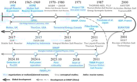
Figure 1.
Timeline of key milestones in Liquid fuel Graphite-based MSRs development.
The concept of MSRs was first proposed in the late 1940s for high-temperature aircraft propulsion. The Aircraft Reactor Experiment (ARE) in 1954 demonstrated the feasibility of using molten salt as both a coolant and a fuel medium. The Molten Salt Reactor Experiment (MSRE) at Oak Ridge National Laboratory (ORNL) achieved criticality in 1965 and operated successfully until 1969, during which extensive operational data and analyses were accumulated, serving as a reference and benchmark for subsequent MSR designs. Building on the MSRE, ORNL further proposed the conceptual design of the Molten Salt Breeder Reactor (MSBR) and subsequently developed the Denatured Molten Salt Reactor (DMSR) concept. However, research on MSRs entered a prolonged stagnation due to shifting priorities and funding constraints.
Since the early 21st century, increasing energy and environmental pressures, together with the inherent safety, high fuel utilization efficiency, and reduced nuclear waste of MSRs, have attracted renewed attention to this technology, resulting in their inclusion in the Generation IV nuclear systems in the future by GIF4. Research institutions in Europe, Japan, the United States, Canada, and China have initiated conceptual design studies and research on MSRs. A recent milestone is the TMSR-LF1 designed and operated by the Shanghai Institute of Applied Physics (SINAP), which achieved full-power operation in 2024 and confirmed the presence of the 233U precursor 233Pa [1].
2.2. System Analysis Code for MSRs
Molten salt reactors (MSRs) employing liquid fuel involve inherently complex processes such as online fuel feeding and reprocessing, transport and release of gaseous fission products, and related multiphysics interactions. Compared with traditional solid-fuel reactors, liquid-fueled MSRs feature stronger coupling among neutronics, thermal-hydraulics, fuel depletion, material corrosion, and structural mechanics across wide temporal and spatial scales, thereby requiring more comprehensive approaches for safety analysis and performance assessment [2]. Table 1 provides a consolidated summary of the MSR system-analysis codes introduced in this subsection.
Early analysis codes coupled point kinetics (PK) with lumped-parameter thermal-hydraulics (TH) models are exemplified by the Murgatroyd [3] code developed for the MSRE. Then, given the similarity between MSRs and light-water reactors (LWRs) in employing flowing coolant as heat transfer medium, many studies have extended mature LWR codes such as RELAP5 [4], SPECTRA [5], and DYN3D [6,7] for MSR applications. For instance, SINAP has not only modified RELAP5 into RELAP5-TMSR [8,9] but also developed the in-house system code TREND [10]. The essential advancements of these codes include (1) extending point-kinetics models to account for delayed neutron precursor (DNP) migration, and (2) developing thermal-hydraulics (TH) models capable of handling internal heat sources, including the implementation of relevant thermophysical properties and heat transfer correlations. While these programs can support fundamental steady-state and transient analyses of MSRs, they remain limited in addressing complex multiphase and multicomponent phenomena such as fuel circulation, gas transport, and chemical corrosion. The limitations arise primarily from the underlying framework design. Built on Fortran-based implementations, these frameworks are efficient and reliable for numerical computation but less suited to meeting modern expectations for extensibility and integrated multiphysics modeling.
To overcome these constraints, broadly validated coarse-grid CFD-based safety analysis tools such as GOTHIC [11] and SAM [12] have been introduced to MSR studies, providing improved treatment of multiphase transport and spatially resolved flow behavior. In parallel, general-purpose multiphysics modeling platforms such as Simulink/Simscape [13,14] and Modelica have been employed for early-stage system simulations, component model development, and coupling with PK and nuclide transport models.

Table 1.
Overview of Typical System Analysis Codes Developed for MSRs.
Table 1.
Overview of Typical System Analysis Codes Developed for MSRs.
| Code/Framework | Language/Platform | Time | Developer/Improver | Key Features |
|---|---|---|---|---|
| Murgatroyd [3] | IBM 7090 | 1962 | ORNL, USA | First-of-its-kind; coupled point kinetics (PK) with lumped-parameter thermal-hydraulics (TH); modeled DNP drift via delayed differential equations. |
| DYN3D-MSR [6,7] | Fortran | 2005 | FZR, German | Derived from LWR code DYN3D; employs nodal expansion method; 1D/3D Neutron diffusion coupled with TH; models DNP drift and specific MSR heat release. |
| SPECTRA [5] | Fortran | 2021 | NRG, The Netherlands | Adapted from LWR code; capable of fission product & DNP transport; includes online reprocessing and burnup analysis for key isotopes. |
| TREND [9,10] | Fortran | 2021 | SINAP, China | In-house developed for Project TMSR; 1D two-group neutron kinetics + DNP migration; 2D TH components; multi-channel core modeling. |
| RELAP5-3D [4] | Fortran | 2022 | Hiroyasu | Extended with molten salt property libraries; uses PK parameters under flow to simulate DNP transport. |
| RELAP5-TMSR [8] | Fortran | 2022 | SINAP, China | Improved PK model accounting for DNP transport; enhanced TH model with internal heat sources. |
| GOTHIC [11] | Fortran | 2022 | ERRI/ZNE, USA | Coarse-mesh CFD multiphysics code; 0D-3D modeling; tracer module for DNP & fission product transport. |
| TRANSFORM [15] | Modelica/ Dymola | 2020 | ORNL, USA | Open-source; object-oriented equation-based modeling; includes TH models for Tracer transport and PK; supports model exchange via FMI standard. |
| Simulink [13,14] | MATLAB | 2024 | Chen | Model-based design; uses Simscape to model nuclide and bubble transport. |
The Modelica modeling language has garnered significant interest in MSR research due to its inherent strengths in multiphysics integration and system-level flexibility. The open-source TRANSFORM library, developed by Greenwood [15], has provided a foundation for modular modeling of advanced reactor systems. Building upon this framework, Fischer [16] conducted detailed modeling of the MSRE core and investigated the coupled neutronic behavior of circulating fuel salt. Separately, Wang [17] applied OpenModelica to study the system dynamics of a liquid-fueled Dual-Fluid Reactor (DFR) and analyze its transient safety characteristics. Collectively, these studies highlight the versatility and potential of Modelica-based frameworks for MSR system simulations, while also underscoring the need for further verification and validation (V&V) to establish confidence in their predictive capabilities for safety and design applications.
Beyond one-dimensional system codes, many efforts have shifted toward high-fidelity core modeling, leading to the development of specialized codes such as NTH-3D [18] and ThorCORE3D [19], as well as the adoption of advanced multiphysics frameworks MOOSE [20] or CFD/FEM platforms (e.g., OpenFOAM [21], COMSOL [22]) for detailed local phenomena. However, these high-fidelity tools generally lack system-level capabilities and are computationally intensive for strongly coupled MSR scenarios.
In summary, while existing system analysis codes each offer unique advantages, they continue to face challenges in flexibility, openness, and integration. TRANSFORM share similar underlying models with system analysis codes like RELAP5. As a result, their intended applications are largely similar, with the main distinctions arising from transient solution strategies, coupling methods, and scalability. Although these tools adopt comparable spatial discretization schemes, the Modelica environment automatically handles transient solutions and multiphysics coupling. This enables users to focus on model development and component interactions, but it also limits opportunities for targeted optimization or methodological refinement for specific transient scenarios. Given these considerations, the present work is built upon the equation-oriented, object-oriented TRANSFORM library [23]. The detailed modeling methodology is described in the following chapter.
3. Modeling Framework
Modelica is an object-oriented, equation-based language renowned for its acausal modeling approach, which enables the direct description of systems through physical conservation laws without predefining input-output causality. This flexibility supports modeling across scales—from basic components to complex energy systems.
In nuclear applications, Modelica has been employed to simulate various reactor types, such the PWRs and SFRs. The TRANSFORM library, developed by ORNL, significantly enhances its practicality for nuclear engineers by offering open-source, reusable components tailored for system-level steady-state and transient analysis of advanced nuclear systems.
Numerically, Modelica models are compiled into systems of differential-algebraic equations (DAEs) or ordinary differential equations (ODEs). Simulation environments such as Dymola (2023x) and OpenModelica (v1.25.0) incorporate efficient solvers that capitalize on the inherent sparsity and structure of these equation systems. By employing optimized matrix processing and structural analysis techniques, these tools significantly enhance computational performance. This efficiency makes Modelica especially well-suited for simulating large-scale, tightly coupled engineering systems, including applications in nuclear power modeling.
While challenges persist in strongly coupled multiphysics scenarios, the Modelica/TRANSFORM framework has demonstrated considerable reliability. This study utilizes the Point Reactor Kinetics module with fuel burnup, Pipe module with tracer transport, Centrifugal Pump, and other related modules from the TRANSFORM library to develop a closed primary loop model of the MSRE, driven by either pump circulation or molten-salt density differences. Based on the foundational pipe model, applied to the core, the out-of-core pipeline model was also developed, and the coupling methodology for decay heat and flow burnup modules was optimized, thereby streamlining the overall modeling process.
Subsequent sections provide detailed descriptions of the key thermal-hydraulic, neutronics, and burnup analysis, which are derived from the original code of the TANSFORM.
3.1. Thermal-Hydraulic Modeling
TRANSFORM has established a flexible and comprehensive thermal-hydraulic (TH) model library applicable to multiple media, including pipes, heat exchangers, turbines, pressure/flow sources, pumps, and valves. This section provides a brief introduction to its thermal-hydraulic models based on the open-source code.
TRANSFORM provides the basic pipe model based on a staggered grid design. As shown in Figure 2, mass and energy conservation are considered within each control volume, while momentum conservation is considered between control volumes. The following conservation equation discretization scheme is obtained under the assumptions of uniform axial discretization, negligible radial gradient, and constant cross sectional area within each control volume.
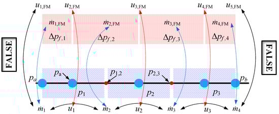
Figure 2.
Schematic diagram of a typical staggered grid of pipe model.
The continuity equation of the control volume i after spatial discretization can be expressed as Formula (1):
In which t is the time, s; V is the volume of the control volume, m3; ṁ is the mass flow rate, kg/s; subscripts “i” indicate number of the control volume.
Typical system-analysis programs require explicit substitution of thermophysical property relations after spatial discretization of the continuity equation. For example, the time derivative of density must be manually expanded using the chain rule as:
In contrast, Modelica employs its Medium module to automatically manage the coupling between state variables like density, pressure, and enthalpy. This approach allows the continuity equation, Equation (1), to be formulated directly as a set of coupled ODEs without requiring manual derivation and substitution of property derivatives.
The energy conservation equation, formulated with internal energy as the state variable, is discretized as follows:
where U represents the internal energy of the control volume, J; while Wb denotes the mechanical work on the fluid, including work due to pressure differences, frictional losses, and gravidity, W; H is the enthalpy flux term, W; QI denotes the heat transfer exchanged between the solid structures and the fluid, W; and finally, QG indicates any internal energy generation sources, such as fission or decay heat.
As illustrated in Figure 2, the momentum equation is discretized using a staggered-grid arrangement. The FlowModule (FM) submodule defines a control volume between two adjacent pressure volumes, and the momentum conservation equation is formulated for this volume as follows:
In which Δx is the length of the volume, m; Iflow represents the net momentum flux through the control volume, kg·m/s; F is the resultant force acting on the fluid within the control volume, N; the subscripts “sp” and “sfg” indicate the pressure gradient force and combined friction-gravity force, respectively.
The model also enables tracer mass (fission products, etc.) transfer and exchange between components to achieve integrated system-level simulations. For the given control volume i, the tracer conservation equation based on atom number is expressed as follows:
In which mC represents the number of atoms of the tracer substance, atoms; ṁC is the net flux of atoms across the control volume surface, atoms/s; smC is the source term, including fission generation, decay, and interphase mass transfer, atoms/s; subscripts “j” indicates the index of the tracer substance.
Neglecting diffusion driven by the tracer concentration gradient and assuming that the tracer convects with the bulk fluid without any relative drift, the tracer atom flux ṁC can be expressed as:
In which C is the atomic concentration of the tracer substance, atoms/kg.
3.2. Coupled Neutronics and Fuel Depletion Modeling
The TRANSFORM library implements a point reactor neutronics model that takes into account the DNP by coupling it with the trace species calculation model in the thermal-hydraulic model [24].
Neglecting an external neutron source, the point-kinetics equations, formulated with the core thermal power P as the primary variable, are given by Equation (7):
In which P is total core thermal power, w; ρ is the net reactivity, accounting for all reactivity feedback mechanisms except the DNP drift effect; β is total delayed neutron fraction; wf is the energy released per fission, J/fission; atoms; is the average number of neutrons released per fission, neutrons/fission; Λ is neutron generation time, s; λ is the decay constant for the DNP, s−1; subscript k indicates the index of the DNP group.
Unlike solid-core point-kinetics models, where DNP remains stationary, MSR must account for the transport of DNP with the flowing fuel. Therefore, in addition to power and reactivity feedback coupling, the transport of DNP is handled within the TH model. Within the active core region, the source term smC in Equation (5) represents the combined contributions from fission generation and decay, and is formulated as:
In which, SFi is the axial power shape factor for control volume i; βk is the delayed neutron fraction for precursor group k.
Building upon the same methodology for DNP transport, the burnup simulation for fission products and actinides is integrated into the trace substance tracking capability of the TH module. This method can express the corresponding source term smC of control volume i as:
In which σ is the total removal rate, accounting for both neutron absorption and decay; β is the total transformation rate from precursor nuclide, via decay or neutron capture.; Fk is the fission yield source term; subscripts k and k − 1 denote the current nuclide and its direct precursor, respectively. Figure 3 shows the simplified burnup model for 135Xe within a one-group neutron spectrum, along with the corresponding generation and removal terms.
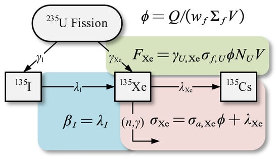
Figure 3.
Schematic diagram of the simplified Xenon-135 decay chain.
Based on the above thermal-hydraulic and neutronic models, multiphysics coupling can be achieved under the acausal modeling paradigm of Modelica. In this paradigm, the solution order among physical fields does not need to be predefined. Each field model interacts with others simply by referencing the required variables in its own conservation equations. This enables transparent coupling of complex multiphysics processes and improves the reproducibility and extensibility of the MSR modeling framework.
3.3. Primary Loop Configuration and Parameters
The MSRE was first brought to criticality in 1965 by ORNL and operated successfully until 1969, during which extensive operational data and analyses were accumulated. These data have since served as a reference and benchmark for subsequent MSR design and modeling studies. The main MSRE system parameters used in this work are taken from the MSRE Design and Operations Report, Part I: Description of Reactor Design (ORNL-TM-728) [25] and Nuclear Analysis, Part III (ORNL-TM-730) [26]. These reports provide detailed descriptions of the MSRE design parameters, core configuration, and key thermal-hydraulic conditions.
Based on these reference parameters, the MSRE primary loop is modeled following the physical layout of the original facility. As shown in Figure 4, the colored region delineates the modeled primary loop, whose nodalization is presented in Figure 5. The circuit comprises the reactor vessel, pump, primary heat exchanger (PHX), and interconnecting piping. In the modeled flow path, the fuel salt circulates upward through the reactor core, discharges into the outlet plenum, and is then propelled sequentially through the hot leg, the main pump, and the discharge section into the PHX for cooling. The cooled salt returns via the cold leg, passes through the annular distributor, and descends through the downcomer into the core inlet plenum, completing the circulation loop upon re-entering the reactor core.
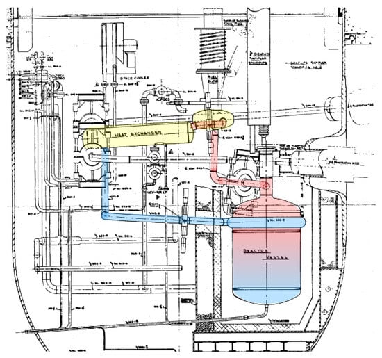
Figure 4.
MSRE reactor cell elevation [25].
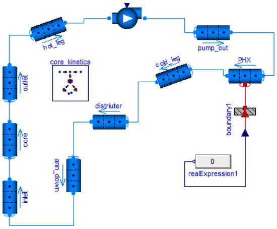
Figure 5.
Basic nodalization of the MSRE primary loop.
The geometric parameters are primarily adopted from Reference [13]. Elevation changes are applied exclusively to the hot leg, cold leg, reactor core, and downcomer to ensure loop elevation closure and to prevent spurious gravitational head effects in natural circulation analysis.
Since the secondary coolant salt loop and the core graphite are not modeled in this study, the associated convective heat transfer is neglected. A constant heat flow is imposed at the primary heat exchanger interface to represent the heat removal by the secondary loop. The primary pump is simplified as a pure flow-rate source providing a constant driving flow to the circuit. This treatment reduces the numerical stiffness of the system and facilitates faster convergence during transient calculations.
Table 2 summarizes the key primary loop thermal-hydraulic parameters used for loop initialization. The point-kinetics parameters of the reactor dynamics model are provided in Table 3 [27]. Together, these parameters enable the steady-state initialization and subsequent transient analysis. The density of the fuel salt, with its compressibility neglected, is given by the following expression:
In which, ρ is the density, kg/m3; T is the temperature, K.
Table 2.
Main thermal-hydraulic parameters of MSRE.
Table 2.
Main thermal-hydraulic parameters of MSRE.
| Parameters | Unit | Value |
|---|---|---|
| Loop mass flow | kg/s | 161.3 |
| Pressure pump outlet | bar | 2.0 |
| Average temperature | °F | 1200.0 |
| Core height | m | 1.6406 |
| Core flow area | m2 | 0.4315 |
Table 3.
DNP Parameters for MSRE with 235U [27].
Table 3.
DNP Parameters for MSRE with 235U [27].
| Group i | Decay Constant λi (s−1) | Delay Fraction βi |
|---|---|---|
| 1 | 0.0124 | 2.23 |
| 2 | 0.0305 | 14.57 |
| 3 | 0.1114 | 13.07 |
| 4 | 0.3013 | 26.28 |
| 5 | 1.140 | 7.66 |
| 6 | 3.010 | 2.80 |
Neutron generation time Λ = 0.00024 s.
Building on the above models, the next section assesses the fidelity of the developed framework through validation against established MSRE transient benchmarks.
4. Model Validation and Results
To validate the TRANSFORM-based MSRE model presented previously, this section conducts a series of benchmark analyses against experimental data and established simulations. Three representative transients are investigated to test the integrated performance of different physical modules and their couplings. The results demonstrate the model’s capability in simulating key phenomena relevant to MSRE operation and safety assessment.
4.1. Pump Start/Stop at Zero Power
To measure the flow-induced reactivity loss of the circulating fuel salt, a series of zero-power pump start and stop experiments were conducted in the MSRE project [27]. Based on the primary loop model shown in Figure 5, the present study performed model verification using the prescribed pump flow rate curve illustrated in Figure 6. A PID-based control model was implemented to dynamically compensate for the loss of DNP transported out of the core and to maintain reactor criticality. The control objective was to maintain constant core power, using the deviation between the target and calculated power as the PID input signal, while the output represents the control rod position or the corresponding reactivity.
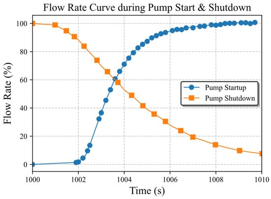
Figure 6.
Flow rate curve during pump start & shutdown [27].
During the pump shutdown process, the control system continuously introduced compensating reactivity to maintain criticality. At 1000 s, a pump trip signal was triggered, and the flow rate decreased as shown in Figure 6. Because the residence time of DNP in the core increased after pump stoppage, the fraction of delayed neutrons became higher, resulting in a positive reactivity. To preserve criticality, the control system inserted control rods to offset this reactivity increase. As shown in Figure 7, the compensated reactivity gradually decreases with the reduction in flow rate. The calculation results obtained by the Modelica model are in close agreement with those of the DYN3D-MSR code, both being slightly higher than the experimental data of MSRE.
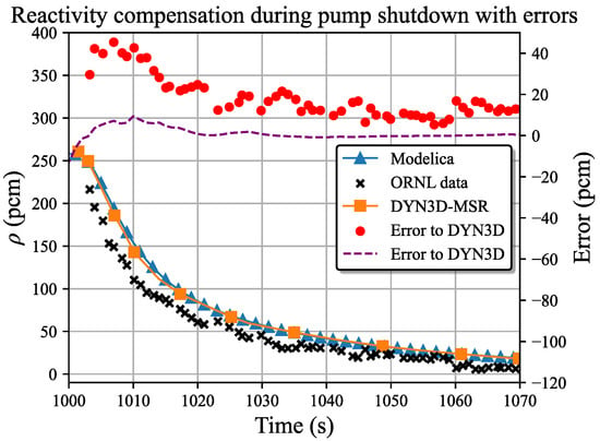
Figure 7.
Reactivity compensation during pump shutdown with errors [7].
During the zero-power pump start process, the DNP are convicted out of the core with the circulating fuel salt, reducing the fraction of delayed neutrons and causing the reactor to become slightly subcritical. To maintain criticality, control rods must be withdrawn to compensate for the flow-induced reactivity loss.
Further numerical analysis reveals that the spatial discretization of the core significantly affects the amplitude of reactivity overshoot and steady-state compensation during the pump start transient. As shown in Figure 8, finer axial meshes better resolve the transport of DNP, leading to larger transient oscillations and stronger compensation. This behavior is due to the averaging assumption within the control volume. A coarser mesh assumes uniform DNP concentration within each cell, which under-resolves the DNP concentration gradient and underestimates the convective transport rate driven by fluid motion. As a result, DNP concentration is overestimated, leading to less compensation by the control rods. The signed error curves in Figure 9 show that when the axial node count nV > 5, the predicted DNP-flow-induced reactivity loss becomes larger than that obtained with DYN3D-MSR. This discrepancy likely reflects the inherent limitations of the one-dimensional approximation in representing spatially distributed transport phenomena.
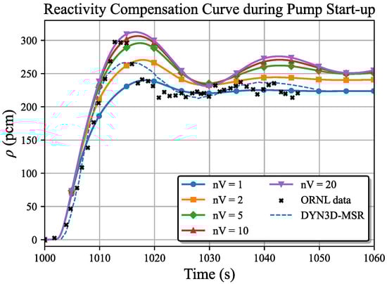
Figure 8.
Reactivity compensation curve during pump start [7] for different core volume divisions nV.
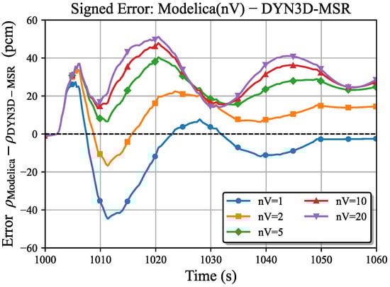
Figure 9.
Signed error during pump start different for different core volume divisions nV.
This mesh sensitivity demonstrates that, although Modelica/TRANSFORM provides robust solutions for ODE-based models after spatial discretization, obtaining physically reliable results still requires a deep understanding of the framework’s modeling assumptions. A spatial discretization strategy aligned with the reactor’s characteristic time scales is essential. This analysis clarifies the origin of mesh-dependent effects and provides methodological guidance for precise system-level simulations of circulating-fuel MSRs. Hence, to balance modeling accuracy with computational cost, a core division scheme with nV = 5 is adopted for all subsequent analyses.
4.2. Xenon Dynamics and Transport Modeling
Beyond the reactivity effects of DNP transport, the movement and burnup of 135Xe introduce significant reactivity feedback. This behavior is modeled using a simplified 135I-135Xe decay chain, as illustrated in Figure 3.
The analysis was conducted under a control scheme that maintained constant reactor power. Figure 10 illustrates the transient process of 135Xe accumulation during steady-state operation. The buildup of 135Xe introduces a growing negative reactivity (xenon poisoning) until an equilibrium is reached. To compensate for this reactivity loss and maintain criticality, the control system automatically adjusts the control rods ρPID, thereby keeping the net reactivity ρnet approximately constant. The non-zero ρnet corresponds to the reactivity loss caused by DNP transport.
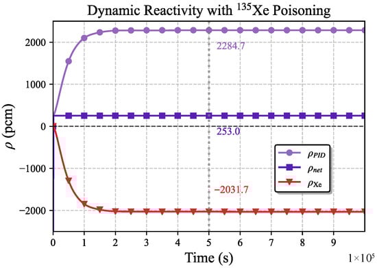
Figure 10.
Xenon equilibrium process reactivity curve at MSRE rated power.
To verify the simulation results, the steady-state xenon distribution was derived based on the two-region model (core and external loop), described by Equations (11)–(13). The corresponding model parameters are listed in Table 4.
Here, N denotes the atomic number density of the nuclide, atom/m3; Σf is the macroscopic fission cross section, m−1; τ denotes the average residence time of the fuel salt in each region, s; the superscripts c and o correspond to parameters within and outside the core.
Table 4.
Xenon equilibrium model parameters.
Table 4.
Xenon equilibrium model parameters.
| Parameters | Unit | Value | |
|---|---|---|---|
| Out-of-core flow time, τo | s | 16.47 | |
| In-core flow time, τc | s | 10.01 | |
| Macroscopic fission cross section of 235U, Σf | m−1 | 0.68 | |
| Thermal power, Q | MW | 8.00 | |
| Equilibrium xenon concentration | Two-region | m−3 | 1.108 × 10²⁰ |
| Modelica | m−3 | 1.110 × 10²⁰ | |
| Relative deviation | % | 0.2457 | |
The equilibrium xenon concentration calculated by the analytical two-region model shows excellent agreement with the result obtained from the detailed Modelica simulation, as summarized in Table 4. This consistency validates the implementation of the xenon dynamics model and demonstrates its capability to accurately capture xenon transport and burnup behavior in circulating-fuel MSR systems.
4.3. Natural Circulation with Decay Heat Transport
After implementing the flowing burnup calculation for fission products, the decay heat power QDH in control volume i can be determined by summing the atomic number densities of the fission products j, as expressed in Equation (14).
Here, Ej denotes the energy deposited in the molten salt per decay, J, which can be obtained from the decay sub library of the ENDF database.
For system-level neutronics–thermal-hydraulics coupling analysis, explicitly modeling the transport and depletion of numerous nuclides throughout the entire loop is computationally prohibitive. To overcome this challenge, a simplified approach is adopted wherein the decay heat is calculated using the pre-calculated groups from the ANSI/ANS-5.1-1971 [28,29] standard for light water reactors, which represents the decay heat contribution by 11 fission product groups and 2 actinide groups [28].
A model of the drain tank was established following the MSRE analysis report [30], as depicted in Figure 11. In this simulation, the reactor was operated at 10 MWt for 1000 h before being shut down by a linear insertion of −$5 in reactivity over 10 s, with the pump flow rate set to zero. With the inclusion of the two actinide groups, the decay heat calculated by the ANSI/ANS-5.1-1971 standard model exceeds the MSRE benchmark, as shown in Figure 12. This confirms that the model with actinides produces a conservative estimate, making it suitable for subsequent analyses.
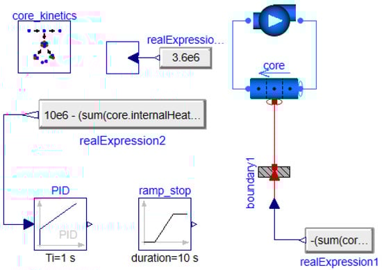
Figure 11.
Decay heat modeling of the MSRE drain tank after shutdown.
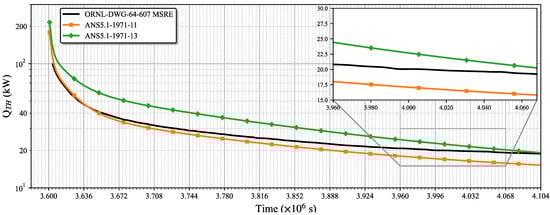
Figure 12.
Comparison of different decay heat models for the MSRE drain tank after shutdown.
Subsequently, decay heat model was employed to analyze the natural circulation capability following reactor shutdown. Due to the lack of key thermal parameters such as pressure drop and heat transfer relationships, the purpose of this analysis was to verify the modeling capability; further research is needed to analyze the specific natural circulation capability.
To smoothly simulate the transition from forced to natural circulation, a centrifugal pump model with speed control was implemented. The nuclide distribution obtained after 1000 h of operation (as shown in Figure 10) was used as the initial condition for decay heat calculation in the core region, while nuclides outside the core were neglected. At the initial time, sufficient negative reactivity was introduced to achieve reactor shutdown.
As illustrated in Figure 13, the pump maintains its nominal speed for 10 s and then linearly decelerates to a complete stop within 100 s. The flow rate decreases accordingly and stabilizes at a low level driven by natural circulation. The decay heat evolution of each component is presented in Figure 14. Since the decay heat level correlates with the mean residence time of molten salt, the highest decay heat is observed in the core region, whereas the lowest occurs near the pump outlet section.
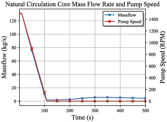
Figure 13.
Mass flow rate response during pump speed decrease.
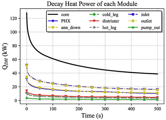
Figure 14.
Component decay heat during natural circulation.
The simulation results in this section confirm that the system can successfully establish natural circulation after shutdown and loss of pump drive, thus ensuring the continuous removal of decay heat. The differences in decay heat levels between the core and various components reflect the flow and heat transfer characteristics of the molten salt under natural circulation.
Due to the large size and stiffness associated with burnup calculations, our tests showed that the current Modelica framework is not yet capable of performing flowing-fuel depletion for the full set of nuclides contributing to decay heat. In addition, since the MSRE is also a thermal-spectrum reactor fueled with U-235, a simplified decay-heat model—the ANSI/ANS-5.1-1971 standard [28,29] used in conventional LWR system codes—was adopted in this study for analysis. As this standard is typically applied with additional conservatism in safety analyses, its use provides reasonable reference value for preliminary thermal-hydraulic design studies. However, considering the thorium-based fuel cycles and online fission-product processing in MSR, the development of a more detailed, MSR-specific decay-heat model or standard would be necessary for the system-analysis applications.
5. Summary and Perspectives
A preliminary system-level model of the Molten Salt Reactor Experiment (MSRE) primary loop was developed using the open-source Modelica/TRANSFORM framework. The model incorporates key physical phenomena such as DNP transport, xenon dynamics, and flow decay heat source, and has been benchmarked against ORNL experimental data and published simulations.
Transient analyses, including zero-power pump start & shutdown, xenon transport, and natural circulation with decay heat, were conducted to verify the coupled neutronic–thermal–hydraulic behavior of the system. The results show that the model can reasonably reproduce characteristic MSRE responses, particularly the flow-induced reactivity changes during pump transients and the buildup of xenon poisoning under steady operation. The sensitivity analysis confirmed that the spatial discretization of the core significantly affects the prediction of DNP drift and reactivity compensation in the one-dimensional system. Finer meshes improve the resolution of DNP transport, leading to larger transient oscillations and stronger compensation, while coarser meshes underestimate these effects. This underscores the importance of choosing an appropriate spatial discretization strategy for reliable, physically consistent results in one-dimensional MSR simulations. The analytical two-region xenon model also exhibited excellent agreement with the numerical results, validating the consistency of xenon transport modeling. Furthermore, the ANSI/ANS-5.1 decay heat correlation was found to provide conservative estimates under MSRE conditions, demonstrating its suitability for system-level decay heat analysis.
Overall, the present study establishes a reliable foundation for further development of system-level simulation tools for circulating-fuel molten salt reactors using the Modelica/TRANSFORM framework. The current MSRE model still adopts simplified representations of the reactor core and major components. Future work will focus on enhancing physical fidelity by introducing multi-channel core modeling, a graphite moderator model, and temperature-dependent reactivity feedback, as well as conducting further sensitivity analyses to assess the impact of key modeling assumptions and parameters on system-level behavior. These improvements will enable more realistic coupling between thermal–hydraulic and neutronic behaviors. In parallel, the modeling framework will be extended toward greater generality and flexibility, incorporating detailed component models and gas transport mechanisms to support broader TMSR system analyses.
Author Contributions
Methodology, J.G.; Software, C.M.; Validation, C.M.; Formal analysis, C.M.; Investigation, C.M.; Writing—original draft preparation, C.M.; Writing—review and editing, J.G.; Visualization, C.M.; Supervision, J.G., Y.Z. and R.Y.; Project administration, J.G., Y.Z. and R.Y.; Funding acquisition, J.G., Y.Z. and R.Y. All authors have read and agreed to the published version of the manuscript.
Funding
This work is supported by the Chinese Academy of Sciences Talent Introduction Youth Program (Grant No. SINAP-YCJH-202303) and the Natural Science Foundation of Shanghai (Grant No. 24ZR1478400) and the National Science Foundation of China (Grant No. 12505204).
Data Availability Statement
The data presented in this study are available on request from the corresponding author, the data are not publicly available due to they are generated from an ongoing model development project.
Conflicts of Interest
The authors declare no conflict of interest.
References
- Overview and Update of MSR Activities within GIF. 2025. Available online: https://www.gen-4.org/resources/webinars/education-and-training-series-97-overview-and-update-msr-activities-within-gif (accessed on 20 September 2025).
- Wu, J.; Chen, J.; Cai, X.; Zou, C.; Yu, C.; Cui, Y.; Zhang, A.; Zhao, H. A Review of Molten Salt Reactor Multi-Physics Coupling Models and Development Prospects. Energies 2022, 15, 8296. [Google Scholar] [CrossRef]
- Nestor, C.W., Jr. Murgatroyd-An IBM 7090 Program for the Analysis of the Kinetics of the MSRE; ORNL-TM-203; Oak Ridge National Lab. (ORNL): Oak Ridge, TN, USA, 1962. [Google Scholar]
- Mochizuki, H. Validation of Neutronics and Thermal-Hydraulics Coupling Model of the RELAP5-3D Code Using the MSRE Reactivity Insertion Tests. Nucl. Eng. Des. 2022, 389, 111669. [Google Scholar] [CrossRef]
- Stempniewicz, M.M.; Roelofs, F. Molten Salt Modelling in SPECTRA Applied to MSRE. Nucl. Eng. Des. 2021, 384, 111483. [Google Scholar] [CrossRef]
- Křepel, J.; Grundmann, U.; Rohde, U.; Weiss, F.-P. DYN1D-MSR Dynamics Code for Molten Salt Reactors. Ann. Nucl. Energy 2005, 32, 1799–1824. [Google Scholar] [CrossRef]
- Křepel, J.; Rohde, U.; Grundmann, U.; Weiss, F.-P. DYN3D-MSR Spatial Dynamics Code for Molten Salt Reactors. Ann. Nucl. Energy 2007, 34, 449–462. [Google Scholar] [CrossRef]
- Li, R.; Cheng, M.; Dai, Z. Improvement of the Delayed Neutron Precursor Transport Model in RELAP5 for Liquid-Fueled Molten Salt Reactor. Nucl. Eng. Des. 2022, 394, 111817. [Google Scholar] [CrossRef]
- Jia, W.; Li, R.; Zuo, X.; Cheng, M.; Liu, F.; Dai, Z. Experimental Validation of Modeling and Simulation Capabilities of RELAP5-TMSR with the NNCL Experimental Facility. Nucl. Technol. 2025, 1–14. [Google Scholar] [CrossRef]
- Yu, W.; Ruan, J.; He, L.; Kendrick, J.; Zou, Y.; Xu, H. Development of TREND Dynamics Code for Molten Salt Reactors. Nucl. Eng. Technol. 2021, 53, 455–465. [Google Scholar] [CrossRef]
- Harvill, R.C.; Lane, J.W.; Link, J.M.; Claybrook, S.W.; George, T.L.; Kindred, T. Steady-State and Transient Benchmarks of GOTHIC to the Molten Salt Reactor Experiment. Nucl. Technol. 2022, 208, 70–99. [Google Scholar] [CrossRef]
- Yang, H.; Cheng, Q.; Zou, L.; Hu, R.; Ji, W. Multiphase Species Transport Modeling for Molten Salt Reactors in the System Analysis Module: Generation, Decay, Deposition, and Extraction of Insoluble Fission Products. Nucl. Technol. 2025, 211, 1960–1985. [Google Scholar] [CrossRef]
- Chen, J.; Brooks, C.S. Modeling of Transient and Steady State Xenon Behavior in the Molten Salt Reactor Experiment. Ann. Nucl. Energy 2024, 204, 110525. [Google Scholar] [CrossRef]
- Chen, J.-Q.; Brooks, C.S. Validation and Application of a Coupled Xenon-Transport and Reactor Dynamic Model of Molten-Salt Reactor Experiment. Nucl. Sci. Tech. 2025, 36, 98. [Google Scholar] [CrossRef]
- Greenwood, M.S.; Betzler, B.R.; Qualls, A.L.; Yoo, J.; Rabiti, C. Demonstration of the Advanced Dynamic System Modeling Tool TRANSFORM in a Molten Salt Reactor Application via a Model of the Molten Salt Demonstration Reactor. Nucl. Technol. 2020, 206, 478–504. [Google Scholar] [CrossRef]
- Fischer, L.; Bureš, L. Application of Modelica/TRANSFORM to System Modeling of the Molten Salt Reactor Experiment. Nucl. Eng. Des. 2024, 416, 112768. [Google Scholar] [CrossRef]
- Wang, M.; He, X.; Macian-Juan, R.; Wang, X. One-Dimensional Transient Analysis of the Dual-Fluid Reactor System. Ann. Nucl. Energy 2021, 162, 108481. [Google Scholar] [CrossRef]
- Li, Z.; Cai, J. Dynamics Analysis of the Graphite-Moderated Channel-Type Molten Salt Reactors Based on Serpent/NTH3D-MSR. Ann. Nucl. Energy 2018, 121, 128–134. [Google Scholar] [CrossRef]
- Zuo, X.; Cheng, M.; Dai, Y.; Yu, K.; Dai, Z. Flow Field Effect of Delayed Neutron Precursors in Liquid-Fueled Molten Salt Reactors. Nucl. Sci. Tech. 2022, 33, 96. [Google Scholar] [CrossRef]
- Pfahl, P.; Chambon, A.; Groth-Jensen, J.; Lauritzen, B. Squirrel: A MOOSE-Based App for Solving Point Kinetics in Molten Salt Reactors. Nucl. Sci. Eng. 2025, 1–13. [Google Scholar] [CrossRef]
- Iaselli, N.; Cammi, A.; Lorenzi, S. Multiphysics Modeling Approach for the Analysis of Noble Metals Deposition in the Molten Salt Fast Reactor. Nucl. Eng. Des. 2025, 439, 114054. [Google Scholar] [CrossRef]
- Hur, J.-M.; Ryu, J.S. Modeling Temperature Distribution in an Electrolytic Reducer Considering Decay and Salt Resistive Heat Effects. Nucl. Eng. Technol. 2025, 57, 103413. [Google Scholar] [CrossRef]
- Greenwood, S. TRANSFORM—A Vision for Modern Advanced Reactor System-Level Modeling and Simulation Using Modelica; Oak Ridge National Laboratory (ORNL): Oak Ridge, TN, USA, 2020. [Google Scholar] [CrossRef]
- Greenwood, M.S.; Betzler, B. Modified Point-Kinetics Model for Neutron Precursors and Fission Product Behavior for Fluid-Fueled Molten Salt Reactors. Nucl. Sci. Eng. 2019, 193, 417–430. [Google Scholar] [CrossRef]
- Robertson, R.C. MSRE Design and Operations Report. Part I Description of Reactor Design; ORNL-TM-728; Oak Ridge National Lab. (ORNL): Oak Ridge, TN, USA, 1965. [Google Scholar] [CrossRef]
- Haubenreich, P.N.; Engel, J.R.; Prince, B.E.; Claiborne, H.C. MSRE Design and Operations Report. Part III. Nuclear Analysis; ORNL-TM-730; Oak Ridge National Lab. (ORNL): Oak Ridge, TN, USA, 1964. [Google Scholar] [CrossRef]
- Prince, B.E.; Ball, S.J.; Engel, J.R.; Haubenreich, P.N.; Kerlin, T.W. Zero-Power Physics Experiments on The Molten-Salt Reactor Experiment; Oak Ridge National Laboratory (ORNL): Oak Ridge, TN, USA, 1968. [Google Scholar] [CrossRef]
- Zhang, S. Calculation of Reactor Kinetics and Core Heat Generation. Nucl. Power Eng. 1991, 12, 92–97. (In Chinese) [Google Scholar]
- ANSI/ANS-5.1-1971; Decay Heat Energy Release Rates Following Shutdown of Uranium-Fueled Thermal Reactors. American Nuclear Society: Westmont, IL, USA, 1973.
- Beall, S.E.; Haubenreich, P.N.; Lindauer, R.B.; Tallackson, J.R. MSRE Design and Operations Report. Part v. Reactor Safety Analysis Report; Oak Ridge National Lab. (ORNL): Oak Ridge, TN, USA, 1964. [Google Scholar]


Disclaimer/Publisher’s Note: The statements, opinions and data contained in all publications are solely those of the individual author(s) and contributor(s) and not of MDPI and/or the editor(s). MDPI and/or the editor(s) disclaim responsibility for any injury to people or property resulting from any ideas, methods, instructions or products referred to in the content. |
© 2025 by the authors. Licensee MDPI, Basel, Switzerland. This article is an open access article distributed under the terms and conditions of the Creative Commons Attribution (CC BY) license.