Abstract
Ammonia can significantly reduce carbon emissions when used in internal combustion engines. However, pure ammonia is considered difficult to ignite and has a slow flame propagation speed, which makes its application challenging. Furthermore, previous research on pure ammonia engines has been based on bench tests, with no vehicle-level tests reported to date. In this study, an engine was tested using pure ammonia as a single fuel in a range-extended hybrid electric vehicle. First, a pure ammonia hybrid power system was implemented in a light-duty vehicle. By motoring the engine instantly to its optimal operating window, the hybrid mode ensures a rapid transition to stable combustion. The results show that, using pure ammonia, the engine can operate stably within a speed range of 1000–3175 rpm. The engine achieves an output power of 45 kW, with an indicated thermal efficiency exceeding 40% under 3175 rpm. Compared to gasoline, pure ammonia has a longer ignition delay but a similar combustion duration. Pure ammonia requires an earlier spark timing and higher intake temperature. The ammonia and NO remain high even after being treated by a three-way catalyst. This research verifies the feasibility of using pure ammonia as a single fuel in hybrid modes, offering broad application prospects in scenarios such as marine power and stationary power generation.
1. Introduction
Against the global backdrop of striving to achieve carbon neutrality, the transition to clean and low-carbon energy in the transportation sector has become an urgent priority. The carbon emissions of internal combustion engines present a critical issue, making the search for and application of green, sustainable alternative fuels paramount. Ammonia (NH3), serving as an ideal hydrogen carrier and zero-carbon fuel, demonstrates significant application potential [1,2,3,4,5]. From a life-cycle assessment perspective, ammonia fuel demonstrates significant carbon reduction potential across various applications, including vehicles [6,7], ships [8,9], and electricity production [6], when produced via appropriate methods. In the passenger vehicle sector, research by Bicer et al. [6] indicated that while conventional gasoline vehicles emit approximately 270 g/km of greenhouse gases, ammonia-powered vehicles emit only 100 g/km, highlighting a substantial reduction. Furthermore, Boero et al. [7] conducted a comprehensive life-cycle assessment of ammonia-fueled internal combustion engine passenger vehicles, evaluating the vehicle, infrastructure, energy production, and operation phases. Their results show that ammonia fuel can significantly reduce global warming potential, fossil resource depletion potential, and ozone depletion potential. Leveraging these advantages, ammonia fuel stands as an ideal fuel for range extenders in extended-range hybrid electric vehicles, exhibiting considerable development prospects.
Ammonia can be liquefied under a pressure of 10 MPa at room temperature, facilitating fuel storage and transportation. Under ideal conditions, ammonia produces only nitrogen and water. Despite these advantages, ammonia also possesses some unfavorable physicochemical properties, as shown in Table 1, such as slow flame propagation speed, narrow flammability limits, and difficulty in ignition [10,11]. These drawbacks pose significant technical challenges for the direct use of pure ammonia in internal combustion engines, making it difficult to ensure stable and efficient combustion. To overcome these challenges, existing research primarily focuses on strategies using ammonia blended with reactive fuels.

Table 1.
Physicochemical properties of typical fuels.
One widely studied combustion mode in diesel engines involves port fuel injection of ammonia and direct injection of diesel. In this mode, the diffusion flame generated by high-pressure diesel ignites the ammonia–air mixture [18]. Zi et al. [19] optimized diesel injection timing and pressure in an ammonia–diesel dual-fuel engine. They achieved an indicated thermal efficiency (ITE) of 52.1% and a 67.9% reduction in greenhouse gas (GHG) emissions at an indicated mean effective pressure (IMEP) of 1.3 MPa and an ammonia energy ratio (AER) of 70%. The AER is defined by the following formula. is the fuel mass flow rate and LHV is the Lower Heating Value of the fuel.
At IMEP = 19 bar and AER = 80%, ITE reached 52.8% with a 75.2% reduction in GHG emissions. Zhang et al. [20] also achieved higher ITE (up to 49.1%) by optimizing the number and timing of diesel injections. Multiple diesel injections significantly reduced the emissions of unburned NH3 (uNH3), total hydrocarbons (THCs), and carbon monoxide (CO), while simultaneously suppressing N2O formation. Under optimized operation conditions, the thermal efficiency of ammonia–diesel engines in some operating points can approach or even exceed that of the original diesel engine; however, the AER remains relatively low, and the engine still produces carbon emissions. Furthermore, at higher AERs, challenges such as poor combustion stability, low thermal efficiency, and high emissions in ammonia–diesel engines remain to be solved. Mi et al. [21] investigated the maximum AER in an ammonia–diesel engine at different speeds. At 900 rpm, the AER could reach 88%, while at 1800 rpm, it was below 80%. Lin et al. [22] explored combustion in an ammonia–diesel engine under high AER conditions. They achieved efficient combustion at AER = 95% under a high compression ratio (CR = 23) and high load (IMEP = 1.475 MPa), proposing a classification of three combustion modes and their impact mechanisms on performance and emissions. However, due to the high AER, ITE only slightly exceeded 46%.
Ammonia–hydrogen engines represent another application mode for ammonia. A common combustion mode involves mixing ammonia and hydrogen in the intake port, forming an ammonia–hydrogen mixture ignited in-cylinder by a spark plug [23]. Frigo et al. [24] compared the combustion of gasoline and ammonia–hydrogen fuel in an engine with a CR of 10.7. Their study showed that the prolonged combustion duration of ammonia–hydrogen fuel led to higher heat transfer losses, resulting in a brake thermal efficiency (BTE) approximately 2% lower than gasoline at the same speed and load. Due to ammonia’s excellent knock resistance, ammonia engines can achieve higher compression ratios compared to gasoline engines. An elevated ratio helps increase the in-cylinder temperature, thereby improving ammonia combustion. Mørch et al. [25] found that further increasing the compression ratio in an ammonia–hydrogen engine could improve ITE and IMEP. Lhuillier et al. [26] investigated the effects of the hydrogen energy ratio and the equivalence ratio on the combustion and emission characteristics of an ammonia–hydrogen engine in a small-displacement engine with a CR of 10.5. Their results indicated that a small amount of hydrogen addition acted as a combustion promoter, achieving a maximum thermal efficiency close to 40%. Excessive hydrogen caused higher heat transfer losses, detrimental to efficiency improvement. In an engine with a CR of 15, Zhu et al. [27] found that increasing the hydrogen energy ratio to 10% effectively improved combustion. At medium load (IMEP = 6.3 bar), the brake thermal efficiency could be increased to 35.8%, though there was still room for further improvement.
However, existing research still has significant limitations. Firstly, the vast majority of studies rely on blended fuel strategies, lacking in-depth validation of pure ammonia as a single fuel. Introducing other fuels increases system complexity. Some scholars have conducted research on pure ammonia engines, but the stable operating range of pure ammonia is narrow, often requiring methods like intake heating. Pyrc et al. [28] attempted to use pure ammonia fuel in SI engines with compression ratios of 8 and 10, but the coefficient of variation (COV) exceeded 30% under both compression ratios. Lhuillier et al. [29] found that in an SI engine with a CR of 10.5, using intake air heated to 50 °C enabled stable pure ammonia combustion under some conditions, but the thermal efficiency was low, with ITE not exceeding 36% at 1500 rpm. Mounaïm-Rousselle et al. [23] found that under pure ammonia conditions with an intake temperature of 323 K and an intake pressure of 0.75 bar, the minimum IMEP was 0.48 MPa. Zhu et al. [27] used a piston (CR = 15) and found that at 1000 rpm, a brake mean effective pressure (BMEP) of 0.78 MPa was the lower load limit for stable operation. Liu et al. [30] discovered that pure ammonia engines have higher stability at low speeds, with misfiring cycles if spark timing is too early and potential flame quenching if spark timing is too late.
Secondly, most explorations are confined to laboratory engine test benches, lacking testing and evaluation in real vehicle systems. Significant differences exist between bench tests and vehicle tests. The results from bench tests often diverge considerably from the operating conditions typically used for engines in range-extended vehicles. Consequently, the feasibility, stability, and emission characteristics of pure ammonia fuel at the vehicle level remain a research gap.
To address the research gap and further advance the practical application of ammonia fuel, this study conducted vehicle tests using pure ammonia fuel on a range-extended hybrid electric vehicle system. The reason for selecting a hybrid electric vehicle as the test platform is that in hybrid mode, the electric motor can rapidly start the ammonia engine and bring it directly to the optimal operating speed range, thus effectively avoiding conventional cold-start issues of ammonia engines. This research involved only adaptive modifications to the original vehicle’s fuel supply system. Across a wide range of operating conditions (1200–3175 rpm), the combustion stability, combustion characteristics, and emission characteristics of the pure ammonia engine were tested and evaluated. Through comparative analysis with gasoline fuel under identical conditions, this study validates the technical feasibility of using pure ammonia as a single fuel in range-extended electric vehicles for the first time at the vehicle level. Simultaneously, the experimental results fully demonstrate that pure ammonia internal combustion engines not only hold potential for vehicle propulsion but also possess broad application prospects in scenarios with high demands for fuel storage and transportation convenience, such as stationary power generation and marine propulsion.
2. Materials and Methods
This study was conducted on a range-extended electric vehicle system from the Dongfeng eπ model. A schematic diagram of the hybrid vehicle system is shown in Figure 1. In this system, the engine is unable to drive the wheels directly, which means that the engine is not connected to the wheels via a mechanical linkage. Instead, the output power of the engine is used to charge the vehicle battery via an inverter. The hybrid vehicle is powered by a four-cylinder spark-ignition engine with a total displacement of 1.5 L, a compression ratio of 13.8, and an ignition energy of 120 mJ. The ignition energy refers to the secondary energy generated by the secondary coil. This ignition energy is the effective energy released by the spark plug into the mixture. To enable the use of ammonia fuel, modifications were made to the fuel supply system. Gaseous ammonia was delivered directly into the intake manifold through a pipeline, with its flow rate controlled by a valve. To ensure sufficient vaporization of ammonia, an ammonia evaporation system was incorporated, powered by the hybrid vehicle’s battery. The engine’s intake and exhaust systems, as well as its structural configuration, remained consistent with the original vehicle, including components such as the turbocharger and throttle valve. To adapt to ammonia fuel, the intake charge air cooler was deactivated, resulting in elevated intake temperatures, which is beneficial for ammonia combustion. The after-treatment device also remained unchanged from the original vehicle, with no modifications implemented.
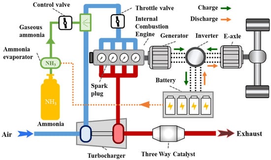
Figure 1.
Schematic diagram of an ammonia-fueled range-extended electric vehicle system.
The in-cylinder pressure in the first cylinder was measured by an AVL pressure sensor ZI45 with a measurement range of 0–200 bar and a linearity of ≤±3%, which transmitted the signal to a combustion analyzer (Kistler Kibox, Winterthur, Switzerland) for online analysis. An oxygen sensor was installed in the exhaust pipe to measure the exhaust gas oxygen concentration and the excess air coefficient (λ). Parameters such as spark timing and throttle opening were controlled by the vehicle’s original engine control unit (ECU). Emissions of NH3, NO, NO2, and N2O were all measured using an FTIR DX4000 analyzer (Gasmet, Helsinki, Finland) with an accuracy of ±1%.
During the experiment, the battery first discharged to drive the motor, stabilizing the engine at the target speed. When using pure ammonia fuel in the vehicle tests, the vehicle’s Power Domain Control Unit (PDCU) adjusted this target speed based on parameters such as coolant temperature and intake air temperature, resulting in deviations between the actual speed and the set value. Subsequently, ammonia was introduced and ignited, while the throttle opening was adjusted to maintain λ near 1.0. If the engine operation remained unstable, the ammonia supply and throttle opening were progressively increased until stable engine operation was achieved. The engine speed varied from 1200 rpm to 3175 rpm, and the engine torque ranged from 69 Nm to 133 Nm.
In this study, the heat release rate was calculated using a single-zone combustion model with the following formula:
where γ represents the specific heat ratio, which is taken as 1.35 for the calculation. φ denotes the engine crank angle, p stands for the in-cylinder pressure, and V indicates the engine cylinder volume.
The total heat release can be calculated by integrating the heat release rate (HRR). The crank angles corresponding to 10%, 50%, and 90% of the total heat release are defined as CA10, CA50, and CA90, respectively, to analyze the combustion phasing and center of combustion during the process. The coefficient of variation (COV) is introduced to characterize the stability of combustion. When COV > 3%, the engine operation is considered unstable. The calculation formulas for COV are shown in Equations (3) and (4):
In Equations (3) and (4), represents the average IMEP over all cycles, denotes the IMEP of the i-th cycle, and N indicates the number of cycles in the experimental condition, with N = 201 in this case.
3. Results
The results are primarily divided into two parts. The first part involves the experimental results of pure ammonia in the vehicle, focusing on the analysis of parameters such as engine speed, load, and spark timing on combustion and emissions. The second part compares the outcomes of using pure ammonia versus gasoline in the vehicle to demonstrate the feasibility of replacing gasoline with pure ammonia while also examining the necessary adjustments required for such a substitution.
3.1. Pure Ammonia
Figure 2 illustrates the variations in in-cylinder pressure and heat release rate under pure ammonia operation at 3175 rpm. In Figure 2a, the light-colored lines represent individual in-cylinder pressures from 201 cycles, while the dark-colored line represents the average in-cylinder pressure across these 201 cycles. The in-cylinder pressure results demonstrate that under stoichiometric combustion conditions, the engine exhibits overall stable combustion without misfiring cycles, and the COV remains below 3%. Figure 2b displays the variation in the average heat release rate, where the maximum heat release rate does not exceed 40 J/deg. Under this operating condition, the engine achieves an ITE of 40.4%, an IMEP of 11.8 bar, a per-cylinder power output exceeding 11 kW, and a total engine power of 45 kW.
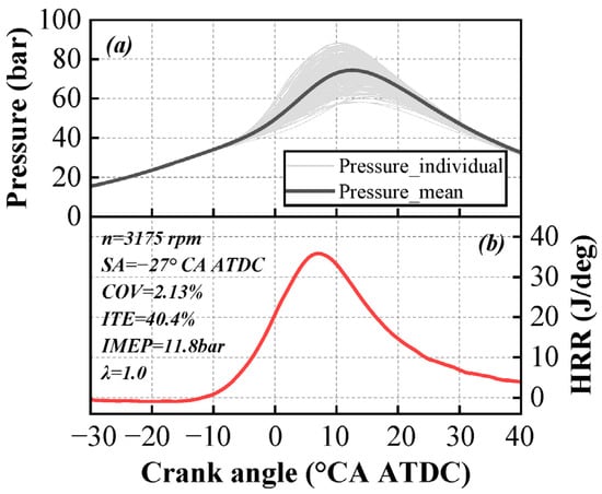
Figure 2.
Variation in in-cylinder pressure (a) and heat release rate (b) for pure ammonia at 3175 rpm.
Figure 3 illustrates the variation in IMEP and the COV with engine speed. This study achieved stable operation of a four-cylinder vehicle engine across a speed range from 1200 rpm to 3175 rpm, with the COV remaining below 3% from low-medium to high speeds. However, regarding the IMEP at different speeds, the engine could maintain stability with an IMEP of around 8 bar in the 1200 to 2000 rpm range, whereas in the 2500 rpm to 3175 rpm range, the IMEP needed to exceed 10 bar to ensure stable operation. The rise in turbulence intensity within the cylinder at high speeds affects the formation of the initial flame kernel, making it susceptible to extinction by high-speed airflow. Therefore, at higher engine speeds, a higher IMEP is required to increase the combustion temperature and enhance combustion stability, which has been reported in previous studies [31,32,33] similarly.
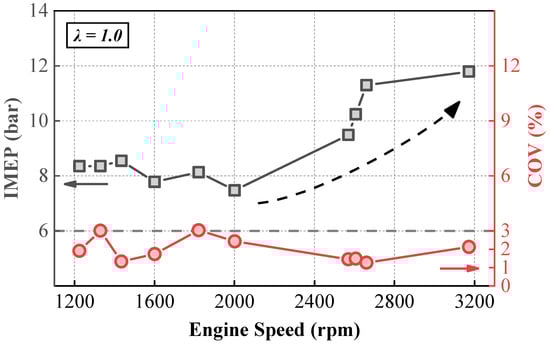
Figure 3.
Variation in IMEP and COV with engine speed.
Figure 4 analyzes the variation patterns of IMEP and the COV under three operating conditions. As shown in Figure 4, IMEP and the COV exhibit opposite trends. As IMEP gradually increases, the combustion temperature rises, enhancing the stability of ammonia combustion and resulting in a gradual decrease in the COV. When IMEP is at 6 bar, the COV exceeds 40%, whereas when IMEP exceeds 10 bar, the COV drops below 3%, indicating stable operation. IMEP is a critical parameter influencing the stability of ammonia engines [27,34,35,36]. Under current engine conditions, achieving stable combustion at low IMEP remains a significant challenge. However, pure ammonia engines operating stably under high IMEP conditions can still be applied in scenarios such as range-extender engines and stationary power generation.
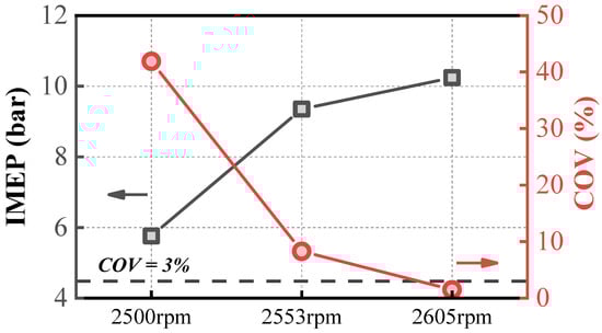
Figure 4.
Variation in IMEP and COV under three operating conditions.
The cylinder pressure and heat release rate curves with different spark timings are shown in Figure 5. As the spark timing is retarded from −29 °CA ATDC to −25 °CA ATDC, the peak values of both cylinder pressure and the heat release rate gradually decrease, and the phases corresponding to these peaks are progressively delayed. The overall shape of the heat release rate curve remains unchanged.
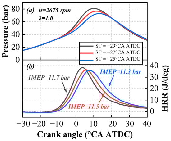
Figure 5.
Variation in in-cylinder pressure (a) and heat release rate (b) with spark timings.
Figure 6 compares the changes in combustion phases under an engine speed of 2675 rpm. As can be observed in Figure 6, as the ignition advance angle decreases, the ignition delay period and the slow combustion period shorten slightly, while the rapid combustion period slightly increases. When the spark timing is progressively retarded, the in-cylinder temperature and pressure become higher, which facilitates the formation and development of the flame kernel. Based on the IMEP results, IMEP gradually increases as the ignition timing is retarded. From the cumulative heat release curve, it can be observed that the retarded ignition timing leads to reduced heat release during the compression phase, which decreases compression negative work and thereby increases IMEP. Additionally, the center of combustion shifts rearward, resulting in a greater total heat release, which also contributes to higher IMEP.
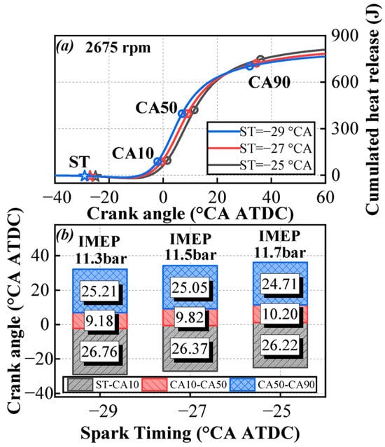
Figure 6.
Variation in cumulated heat release (a) and combustion phases (b) with spark timings under an engine speed of 2675 rpm.
As can be seen in Figure 7, under both operating conditions (a) and (b), although the COV remains below 3%, indicating stable engine operation, the COV slightly increases as the ignition advance angle decreases. This suggests that pure ammonia engines are better suited for earlier ignition strategies. If the spark timing is retarded, the rapid combustion period and slow combustion period progressively move away from the top dead center, leading to decreased temperature and pressure, which adversely affects ammonia combustion.
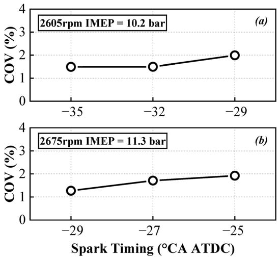
Figure 7.
Variation in COV with spark timings under 2605 rpm (a) and 2675 rpm (b).
This study also collected emission data from pure ammonia operation after post-treatment. Figure 8 presents the emission results for NH3, NO, NO2, and N2O. In previous studies [3,16,24,25,26,37,38,39], emission data primarily focused on engine-out emissions, where unburned NH3 levels were high, exceeding nitrogen oxide emissions and resulting in an ammonia-to-nitrogen oxide ratio greater than 1 in the exhaust. After treatment with the three-way catalyst (TWC) system, unburned NH3 emissions are significantly reduced, while nitrogen oxide emissions slightly increase. Additionally, it is noteworthy that N2O emissions are relatively high. A possible reason is that the original TWC is primarily platinum-based, which exhibits strong oxidative properties at higher exhaust temperatures. This promotes the reactions 4NH3 + 5O2 → 4NO + 6H2O and 2NH3 + 2O2 → N2O + 3H2O [40], leading to significant generation of NO and N2O. Regarding the original TWC system, on the one hand, the ammonia-to-nitrogen oxide ratio in the exhaust can be adjusted to a more desirable range, facilitating further after-treatment control. On the other hand, given that the global warming potential of N2O is 298 times that of CO2, the significant emission of N2O poses new challenges for the post-treatment system.
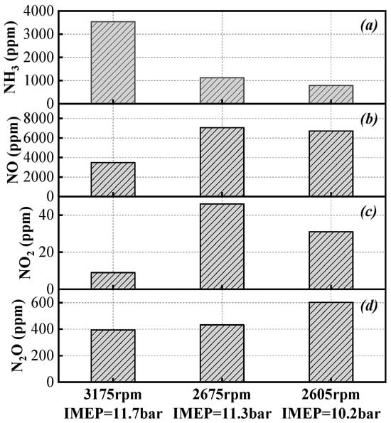
Figure 8.
NH3 (a), NO (b), NO2 (c), and N2O (d) emissions after post-treatment under three operating conditions.
3.2. Comparison of Pure Ammonia and Gasoline
Figure 9a,b present the variations in in-cylinder pressure and heat release rate curves for pure ammonia and gasoline, respectively, under operating conditions around 3000 rpm and around 2500 rpm. Analysis of the in-cylinder pressure reveals that during the compression phase, the pressure for gasoline is lower than that for pure ammonia. The peak in-cylinder pressure of pure ammonia is higher than that of gasoline for two reasons. First, due to the larger air requirement and higher intake temperature for ammonia combustion, the intake pressure needs to be set higher, which leads to higher peak pressure. Second, the combustion of pure ammonia requires a larger ignition advance angle, resulting in an earlier combustion phase and, consequently, a higher peak in-cylinder pressure. Regarding the heat release rate, the peak value for gasoline also appears later in the cycle. During the later stages of combustion, the heat release rate curve for gasoline declines more rapidly, while the curve for ammonia exhibits a gradual decline. This indicates that during the post-combustion phase, as in-cylinder temperature decreases, the ammonia combustion reaction rate slows down, thereby affecting the heat release process.
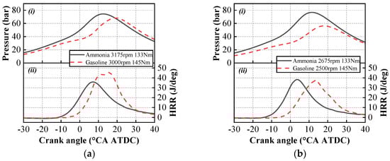
Figure 9.
Variation in in-cylinder pressure (i) and heat release rate (ii) of gasoline and pure ammonia under similar operating conditions: (a) the operating condition of 3000 rpm; (b) the operating condition of 2500 rpm.
Figure 10 compares the combustion duration of gasoline and pure ammonia under two operating conditions. It can be observed in Figure 10 that the ignition delay and slow combustion duration (CA50-CA90) of pure ammonia are significantly longer than those of gasoline. However, the fast combustion duration, defined as CA10-CA50, is similar for both pure ammonia and gasoline. Under low-temperature conditions, the initial dehydrogenation reaction of ammonia proceeds at a slow rate [41,42,43]. Consequently, the ignition delay period is prolonged. Under high-speed and high-tumble-ratio conditions, the turbulent flame speed increases significantly, which enhances the propagation of the ammonia flame. As a result, the rapid combustion phase becomes comparable to that of gasoline. During the later stages of combustion, as the piston descends, the in-cylinder temperature of ammonia combustion decreases compared to gasoline, leading to an extended slow-burning phase [44]. This phenomenon indicates that under suitable operating conditions and engine design, ammonia fuel can serve as a substitute for gasoline.
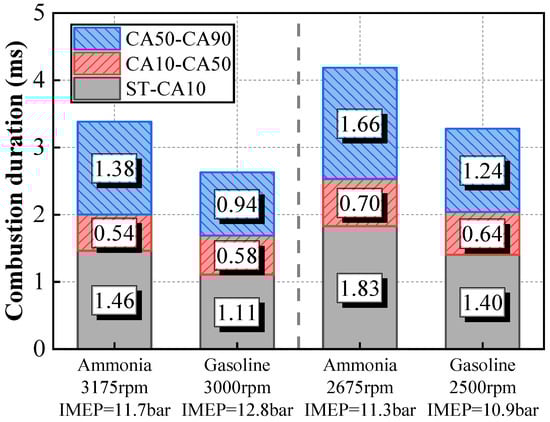
Figure 10.
The combustion phases of gasoline and pure ammonia under different operating conditions.
Figure 11 presents the engine performance characteristics under gasoline and pure ammonia operations. As shown in Figure 11, within the investigated test conditions, the IMEP of pure ammonia operation is slightly lower compared to that of gasoline. Although the COV for both gasoline and pure ammonia conditions remains below 3%, indicating stable combustion, the COV for pure ammonia operation is even lower. Previous studies [23,34,45] have suggested poor combustion stability for pure ammonia. However, vehicle tests demonstrate that under appropriate operating conditions, the combustion stability of pure ammonia fuel can reach levels comparable to, or even exceed, that of gasoline. This confirms the potential of pure ammonia fuel for practical engine applications. Regarding the maximum burst pressure, pure ammonia exhibits higher values than gasoline. This is attributed to the higher intake pressure associated with pure ammonia operation, combined with its larger ignition advance angle and earlier occurrence of CA50, which collectively result in increased maximum in-cylinder pressure and impose more stringent requirements on engine design.
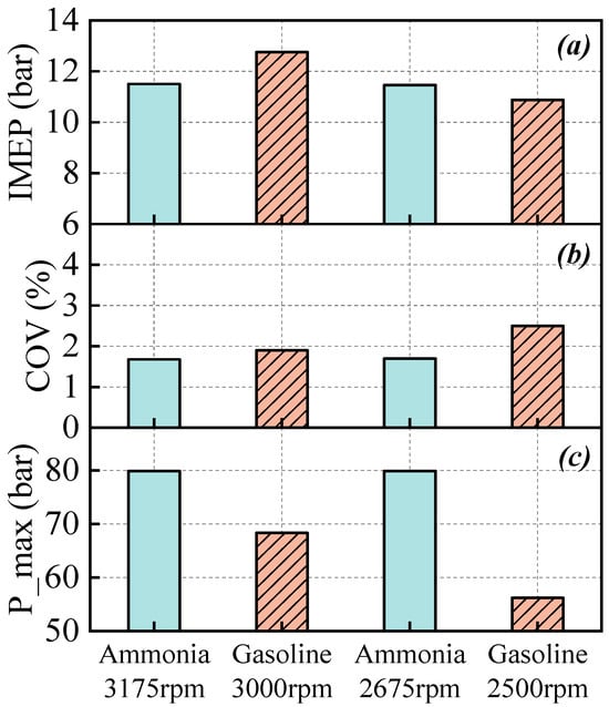
Figure 11.
The IMEP (a), COV (b) and maximum of in-cylinder pressure (c) under gasoline and pure ammonia operations.
Figure 12a,b illustrate the operational boundaries for ammonia and gasoline under two different conditions. The engine coolant temperature boundaries for gasoline and ammonia are similar. However, since the intercooler is inactive during ammonia operation, the intake manifold temperature is significantly higher than in gasoline operation. This elevated temperature facilitates ammonia combustion and enhances its stability. Due to the low energy density of ammonia, a larger volume of fresh air is required to achieve a comparable combustion load. Simultaneously, the increased intake temperature reduces the air density. These two factors collectively lead to a rise in intake pressure. Based on previous analysis, ammonia has a longer ignition delay period. To allow sufficient time for flame development, the spark timing in ammonia operation is more advanced. The above analysis indicates that ammonia combustion imposes new requirements on the intake boosting system, while the ignition strategy must also be adjusted to accommodate the combustion characteristics of ammonia.
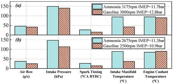
Figure 12.
The operational boundaries for ammonia and gasoline under about 3000 rpm (a) and 2500 rpm (b).
4. Conclusions
Ammonia, as a zero-carbon fuel, holds significant application potential in internal combustion engines. This study tested an engine using pure ammonia as the sole fuel in a range-extended hybrid electric vehicle. Apart from modifications to the fuel supply system, no other changes were made to the engine or the vehicle. The experimental results are as follows:
- (1)
- Under pure ammonia operation, the engine achieved stable operation within a speed range of 1200–3175 rpm. As the engine speed increased, the required IMEP for stable operation gradually rose. Reducing the ignition advance angle shortened the ignition delay period but slightly increased the COV and reduced combustion stability.
- (2)
- At 3175 rpm, the engine achieved an output power of 45 kW, with an indicated thermal efficiency exceeding 40%.
- (3)
- In terms of emissions, even after treatment by a TWC, unburned ammonia and NO emissions remained relatively high, though the ammonia-to-nitrogen oxide ratio was significantly reduced. Additionally, substantial N2O emissions were generated after TWC treatment.
- (4)
- Compared with gasoline, pure ammonia exhibited a longer ignition delay period but a similar combustion duration, necessitating a larger ignition advance angle. Regarding operational boundaries, due to the deactivation of the intake charge air cooler, the intake temperature for pure ammonia was much higher than for gasoline. The intake air volume and intake pressure of pure ammonia were also higher than those of gasoline.
In summary, several operational recommendations for pure ammonia engines are proposed. To enhance combustion, the intake temperature should be increased by avoiding charge air cooling, while a larger ignition advance angle is essential to compensate for the prolonged ignition delay of ammonia. Structurally, the cylinder head should be designed with higher pressure resistance to withstand potential high peak in-cylinder pressures. Regarding the after-treatment system, selective catalytic reduction (SCR) and an ammonia slip catalyst (ASC) are required to control significant unconventional emissions. To improve ASC efficiency, operating conditions that achieve elevated exhaust gas temperatures and higher oxygen concentrations in the exhaust should be selected.
This study validates the feasibility of pure ammonia as a single fuel in hybrid modes through range-extended electric vehicle testing. The ability to bypass low-load instability by motoring the engine to optimal conditions provides a robust solution to conventional cold-start limitations. The successful operation of this ammonia–electric hybrid mode also demonstrates the broad application prospects in other fields, such as stationary power generation.
Author Contributions
Conceptualization, R.L. and Y.Q.; methodology, Q.S., R.L., H.P. and Y.Q.; software, Q.S. and H.P.; validation, Q.S., H.P. and Z.L.; formal analysis, Q.S.; investigation, W.Z. and Q.C.; resources, R.L. and W.Z.; data curation, Q.S. and H.P.; writing—original draft preparation, Q.S.; writing—review and editing, Q.S.; visualization, Q.S.; supervision, Y.Q.; project administration, Z.W.; funding acquisition, Z.W. All authors have read and agreed to the published version of this manuscript.
Funding
This research received no external funding.
Data Availability Statement
The authors do not have permission to share data.
Conflicts of Interest
Authors Rulong Li and Hongjian Pan were employed by the company Dongfeng Motor Corporation. The remaining authors declare that the research was conducted in the absence of any commercial or financial relationships that could be construed as a potential conflict of interest.
Abbreviations
The following abbreviations are used in this manuscript:
| AER | Ammonia Energy Ratio |
| ASC | Ammonia Slip Catalyst |
| ATDC | After Top Dead Center |
| BMEP | Brake Mean Effective Pressure |
| BTDC | Before Top Dead Center |
| BTE | Brake Thermal Efficiency |
| CA | Crank Angle |
| CA10 | Crank Angle At 10% Mass Fraction Burned |
| CA50 | Crank Angle At 50% Mass Fraction Burned |
| CA90 | Crank Angle At 90% Mass Fraction Burned |
| CI | Compression Ignition |
| COV | Coefficient Of Variation |
| CR | Compression Ratio |
| ECU | Engine Control Unit |
| GHG | Greenhouse Gas |
| HRR | Heat Release Rate |
| IMEP | Indicated Mean Effective Pressure |
| ITE | Indicated Thermal Efficiency |
| PDCU | Power Domain Control Unit |
| SCR | Selective Catalytic Reduction |
| SI | Spark Ignition |
| ST | Spark Timing |
| TDC | Top Dead Center |
| TWC | Three-Way Catalytic Converter |
References
- Qi, Y.; Liu, W.; Liu, S.; Wang, W.; Peng, Y.; Wang, Z. A Review on Ammonia-Hydrogen Fueled Internal Combustion Engines. eTransportation 2023, 18, 100288. [Google Scholar] [CrossRef]
- Gray, J.T.; Dimitroff, E.; Meckel, N.T.; Quillian, R.D. Ammonia Fuel—Engine Compatibility and Combustion. SAE Technical Paper 1966, 660156. [Google Scholar] [CrossRef]
- Sun, Q.; Qi, Y.; Lin, Z.; Liu, Y.; Zhu, W.; Wang, Z. Combustion and Emission Characteristics of an Ammonia-Hydrogen Engine Using Hydrogen-Nitrogen Jet Ignition. Energy 2025, 328, 136544. [Google Scholar] [CrossRef]
- Wang, Z.; Qi, Y.; Sun, Q.; Lin, Z.; Xu, X. Ammonia Combustion Using Hydrogen Jet Ignition (AHJI) in Internal Combustion Engines. Energy 2024, 291, 130407. [Google Scholar] [CrossRef]
- Huang, Z. Fuel Blend Combustion for Decarbonization. Proc. Combust. Inst. 2024, 40, 105776. [Google Scholar] [CrossRef]
- Bicer, Y.; Dincer, I. Life Cycle Assessment of Ammonia Utilization in City Transportation and Power Generation. J. Clean. Prod. 2018, 170, 1594–1601. [Google Scholar] [CrossRef]
- Boero, A.; Mercier, A.; Mounaïm-Rousselle, C.; Valera-Medina, A.; Ramirez, A.D. Environmental Assessment of Road Transport Fueled by Ammonia from a Life Cycle Perspective. J. Clean. Prod. 2023, 390, 136150. [Google Scholar] [CrossRef]
- Wang, H.; Zhou, P.; Jeong, B.; Mesbahi, A.; Mujeeb-Ahmed, M.P.; Jang, H.; Giannakis, A.; Sykaras, K.; Papadakis, A. Life Cycle Analysis of Ammonia Fuelled Ship—Case Ship Studies for Marine Vessels. J. Clean. Prod. 2025, 520, 146105. [Google Scholar] [CrossRef]
- Chalaris, I.; Jeong, B.; Jang, H. Application of Parametric Trend Life Cycle Assessment for Investigating the Carbon Footprint of Ammonia as Marine Fuel. Int. J. Life Cycle Assess. 2022, 27, 1145–1163. [Google Scholar] [CrossRef]
- Ma, F.; Guo, L.; Li, Z.; Zeng, X.; Zheng, Z.; Li, W.; Zhao, F.; Yu, W. A Review of Current Advances in Ammonia Combustion from the Fundamentals to Applications in Internal Combustion Engines. Energies 2023, 16, 6304. [Google Scholar] [CrossRef]
- Zhou, L.; Zhong, L.; Liu, Z.; Wei, H. Toward Highly-Efficient Combustion of Ammonia–Hydrogen Engine: Prechamber Turbulent Jet Ignition. Fuel 2023, 352, 129009. [Google Scholar] [CrossRef]
- Kobayashi, H.; Hayakawa, A.; Somarathne, K.D.K.A.; Okafor, E.C. Science and Technology of Ammonia Combustion. Proc. Combust. Inst. 2019, 37, 109–133. [Google Scholar] [CrossRef]
- Hayakawa, A.; Goto, T.; Mimoto, R.; Arakawa, Y.; Kudo, T.; Kobayashi, H. Laminar Burning Velocity and Markstein Length of Ammonia/Air Premixed Flames at Various Pressures. Fuel 2015, 159, 98–106. [Google Scholar] [CrossRef]
- Han, W.; Dai, P.; Gou, X.; Chen, Z. A Review of Laminar Flame Speeds of Hydrogen and Syngas Measured from Propagating Spherical Flames. Appl. Energy Combust. Sci. 2020, 1–4, 100008. [Google Scholar] [CrossRef]
- Hu, E.; Li, X.; Meng, X.; Chen, Y.; Cheng, Y.; Xie, Y.; Huang, Z. Laminar Flame Speeds and Ignition Delay Times of Methane–Air Mixtures at Elevated Temperatures and Pressures. Fuel 2015, 158, 1–10. [Google Scholar] [CrossRef]
- Liao, Y.-H.; Roberts, W.L. Laminar Flame Speeds of Gasoline Surrogates Measured with the Flat Flame Method. Energy Fuels 2016, 30, 1317–1324. [Google Scholar] [CrossRef]
- Chong, C.T.; Hochgreb, S. Measurements of Laminar Flame Speeds of Liquid Fuels: Jet-A1, Diesel, Palm Methyl Esters and Blends Using Particle Imaging Velocimetry (PIV). Proc. Combust. Inst. 2011, 33, 979–986. [Google Scholar] [CrossRef]
- Dimitriou, P.; Javaid, R. A Review of Ammonia as a Compression Ignition Engine Fuel. Int. J. Hydrogen Energy 2020, 45, 7098–7118. [Google Scholar] [CrossRef]
- Zi, Z.; Jin, S.; Shi, T.; Zhu, L.; Wu, B. Effect of Ammonia Energy Fraction and Diesel Injection Strategy on Load Extension and Greenhouse Gas Reduction Potential of Ammonia-Diesel Premixed-Charge Compression Ignition Engine. Fuel 2025, 398, 135351. [Google Scholar] [CrossRef]
- Zhang, F.; Yang, C.; Wang, Z.; Cheng, X. Comparison of Diesel Single/Double/Triple Injection Strategies and Early/Late Compression Ignition Regimes in an Ammonia/Diesel Dual-Fuel Engine. Energy 2025, 322, 135753. [Google Scholar] [CrossRef]
- Mi, S.; Shi, Z.; Wu, H.; Zheng, L.; Zhao, W.; Qian, Y.; Lu, X. Expanding High Ammonia Energy Ratios in an Ammonia-Diesel Dual-Fuel Engine across Wide-Range Rotational Speeds. Appl. Therm. Eng. 2024, 251, 123608. [Google Scholar] [CrossRef]
- Lin, Z.; Liu, Y.; Chen, Q.; Sun, Q.; Zhu, W.; Qi, Y.; Wang, Z. Experimental Study on the Combustion Pattern in an Ammonia Engine Using Micro Diesel Ignition. Energy 2025, 320, 135480. [Google Scholar] [CrossRef]
- Mounaïm-Rousselle, C.; Bréquigny, P.; Dumand, C.; Houillé, S. Operating Limits for Ammonia Fuel Spark-Ignition Engine. Energies 2021, 14, 4141. [Google Scholar] [CrossRef]
- Frigo, S.; Gentili, R. Analysis of the Behaviour of a 4-Stroke Si Engine Fuelled with Ammonia and Hydrogen. Int. J. Hydrogen Energy 2013, 38, 1607–1615. [Google Scholar] [CrossRef]
- Mørch, C.S.; Bjerre, A.; Gøttrup, M.P.; Sorenson, S.C.; Schramm, J. Ammonia/Hydrogen Mixtures in an SI-Engine: Engine Performance and Analysis of a Proposed Fuel System. Fuel 2011, 90, 854–864. [Google Scholar] [CrossRef]
- Lhuillier, C.; Brequigny, P.; Contino, F.; Rousselle, C. Performance and Emissions of an Ammonia-Fueled SI Engine with Hydrogen Enrichment; SAE Technical Paper 2019-24-0137; SAE International: Warrendale, PA, USA, 2019. [Google Scholar] [CrossRef]
- Zhu, T.; Yan, X.; Gao, Z.; Qiu, Y.; Zhu, L.; Huang, Z. Combustion and Emission Characteristics of Ammonia-Hydrogen Fueled SI Engine with High Compression Ratio. Int. J. Hydrogen Energy 2024, 62, 579–590. [Google Scholar] [CrossRef]
- Pyrc, M.; Gruca, M.; Tutak, W.; Jamrozik, A. Assessment of the Co-Combustion Process of Ammonia with Hydrogen in a Research VCR Piston Engine. Int. J. Hydrogen Energy 2023, 48, 2821–2834. [Google Scholar] [CrossRef]
- Lhuillier, C.; Brequigny, P.; Contino, F.; Mounaïm-Rousselle, C. Experimental Study on Ammonia/Hydrogen/Air Combustion in Spark Ignition Engine Conditions. Fuel 2020, 269, 117448. [Google Scholar] [CrossRef]
- Liu, Z.; Zhou, L.; Wei, H. Experimental Investigation on the Performance of Pure Ammonia Engine Based on Reactivity Controlled Turbulent Jet Ignition. Fuel 2023, 335, 127116. [Google Scholar] [CrossRef]
- Sun, Q.; Qi, Y.; Lin, Z.; Liu, Y.; Zhu, W.; Chen, Q.; Peng, Y.; Wang, Z. Experimental Study on Combustion and Emission Characteristics of a Pure Ammonia Engine with Spark Ignition. Energy 2025, 341, 139346. [Google Scholar] [CrossRef]
- Alvarez, L.F.; Ulishney, C.J.; Askari, O.; Dumitrescu, C.E. Neat Ammonia Use in a Heavy-Duty Diesel Engine Converted to Spark Ignition Focused on Lean Operation. Fuel 2025, 382, 133786. [Google Scholar] [CrossRef]
- Ambalakatte, A.; Cairns, A.; Geng, S.; Varaei, A.; Hegab, A.; Harrington, A.; Hall, J.; Bassett, M. Experimental Comparison of Spark and Jet Ignition Engine Operation with Ammonia/Hydrogen Co-Fuelling; SAE Technical Paper 2024-01-2109; SAE International: Warrendale, PA, USA, 2024. [Google Scholar] [CrossRef]
- Lanni, D.; Galloni, E.; Fontana, G.; D’Antuono, G. Assessment of the Operation of an SI Engine Fueled with Ammonia. Energies 2022, 15, 8583. [Google Scholar] [CrossRef]
- Xin, G.; Ji, C.; Wang, S.; Hong, C.; Meng, H.; Yang, J.; Su, F. Experimental Study on the Load Control Strategy of Ammonia-Hydrogen Dual-Fuel Internal Combustion Engine for Hybrid Power System. Fuel 2023, 347, 128396. [Google Scholar] [CrossRef]
- Liu, Z.; Wei, H.; Shu, G.; Zhou, L. Ammonia-Hydrogen Engine with Reactivity-Controlled Turbulent Jet Ignition (RCTJI). Fuel 2023, 348, 128580. [Google Scholar] [CrossRef]
- Xin, G.; Ji, C.; Wang, S.; Meng, H.; Chang, K.; Yang, J. Effect of Ammonia Addition on Combustion and Emission Characteristics of Hydrogen-Fueled Engine under Lean-Burn Condition. Int. J. Hydrogen Energy 2022, 47, 9762–9774. [Google Scholar] [CrossRef]
- Qi, Y.; Wang, W.; Wang, Z. Combustion and Emission Characteristics of an Ammonia-Hydrogen Engine Under Passive- and Active-Jet Ignition; SAE Technical Paper 2024-01-2109; SAE International: Warrendale, PA, USA, 2024. [Google Scholar] [CrossRef]
- Pochet, M.; Truedsson, I.; Foucher, F.; Jeanmart, H.; Contino, F. Ammonia-Hydrogen Blends in Homogeneous-Charge Compression-Ignition Engine; SAE Technical Paper 2017-24-0087; SAE International: Warrendale, PA, USA, 2017. [Google Scholar] [CrossRef]
- Wang, X.; Chen, R.; Li, T.; Huang, S.; Zhou, X.; Li, S.; Wang, N.; Li, Z.; Li, G.; Guo, X. A Novel Exhaust Aftertreatment Technology for the Simultaneous Elimination of NO, NO2 and NH3 of Pilot-Diesel-Ignited Ammonia Engines Based on the Active Exhaust Diversion. J. Energy Inst. 2025, 119, 101981. [Google Scholar] [CrossRef]
- Pochet, M.; Dias, V.; Moreau, B.; Foucher, F.; Jeanmart, H.; Contino, F. Experimental and Numerical Study, under LTC Conditions, of Ammonia Ignition Delay with and without Hydrogen Addition. Proc. Combust. Inst. 2019, 37, 621–629. [Google Scholar] [CrossRef]
- Hurault, F.; Fenard, Y.; Brequigny, P.; Moreau, B.; Haidous, Y.; Foucher, F.; Mounaïm-Rousselle, C. Experimental and Numerical Ignition Delay Times Comparison for Ammonia Mechanisms at High Pressure. Proc. Combust. Inst. 2024, 40, 105625. [Google Scholar] [CrossRef]
- Zhang, R.; Zhang, Q.; Qi, Y.; Chu, Z.; Yang, B.; Wang, Z. A Study on Measuring Ammonia-Hydrogen IDTs and Constructing an Ammonia-Hydrogen Combustion Mechanism at Engine-Relevant Thermodynamic and Fuel Concentration Conditions. Int. J. Hydrogen Energy 2024, 82, 786–800. [Google Scholar] [CrossRef]
- Dong, P.; Chen, S.; Dong, D.; Wei, F.; Lu, M.; Wang, P.; Long, W. Characteristics of Ammonia Premixture Combustion Ignited by a Gasoline Ignition Chamber. Int. J. Hydrogen Energy 2024, 49, 923–932. [Google Scholar] [CrossRef]
- Carsten Jespersen, M.; Østerby Holst Rasmussen, T.; Ivarsson, A. Widening the Operation Limits of a SI Engine Running on Neat Ammonia. Fuel 2024, 358, 130159. [Google Scholar] [CrossRef]
Disclaimer/Publisher’s Note: The statements, opinions and data contained in all publications are solely those of the individual author(s) and contributor(s) and not of MDPI and/or the editor(s). MDPI and/or the editor(s) disclaim responsibility for any injury to people or property resulting from any ideas, methods, instructions or products referred to in the content. |
© 2025 by the authors. Licensee MDPI, Basel, Switzerland. This article is an open access article distributed under the terms and conditions of the Creative Commons Attribution (CC BY) license (https://creativecommons.org/licenses/by/4.0/).