Abstract
Rising summer temperatures are increasing the demand for shading solutions and indoor cooling technologies. Given the substantial surface area of gable roofs, their effective shading plays a significant role in thermal management. While modern buildings often feature heat-insulated roofs equipped with photovoltaic panels or infrared-reflective coatings, such measures are frequently unsuitable for traditional, particularly heritage-protected structures. For this specific category of buildings, ventilated infrared (IR) shielding elements installed on the underside of rafters offer a promising approach to reduce surface temperatures and limit radiative heat transfer to attics or upper living spaces. This study evaluates performance-optimized IR shading systems for heritage roofs, focusing on material selection and emissivity effects. Results indicate that ventilated OSB panels with low-emissivity coatings achieve up to 53% thermal load reduction compared to unshielded conditions. Ventilation of the rafter fields emerges as the critical factor for the functional performance of such IR shading elements.
1. Introduction
Infrared radiation (IR) management is critical for passive cooling strategies in heritage architecture, where external interventions are restricted [1], helping to minimize heat transfer and optimize indoor climate conditions, thereby contributing to energy-efficient building performance [2].
Roofs, being among the most exposed components of a building envelope, present particular challenges for thermal protection. Minimizing heat gain through the roof can significantly reduce cooling energy demand [3]. In hot climates, the solar reflectance of a roof plays a vital role in thermal performance. Roofs with light colors or reflective surfaces can reduce heat absorption by up to 30% compared to darker roofs [4], leading to lower cooling demands and enhanced indoor comfort. One study introduced a method to quantify this benefit through an effective R-value, showing that reflective roofing can partially replace conventional insulation [5]. The research also considered the effects of aging and soiling on reflectivity, offering a model to predict long-term performance. These insights support the integration of roof color considerations into building energy efficiency standards for warm regions.
Previous studies highlight the role of reflective coatings and radiant barriers in reducing heat flux, particularly in hot climates. However, their applicability to heritage roofs is limited due to aesthetic and structural constraints [6]. Mass insulation lowers indoor heat gain but can increase external surface temperatures, intensifying the urban heat island effect [7]. Performance improves when white or selective coatings are applied, especially in combination with insulation [4]. These cost-effective passive cooling strategies are especially beneficial for nonresidential buildings in hot climates [8].
Combining reflective exterior coatings with low-emittance interior layers (e.g., aluminum) yields optimal thermal performance [9], though external measures are generally more effective at reducing cooling loads than internal ones [10]. In the literature, both ‘radiant barrier’ [11] and ‘IR shading’ [12] are used to describe methods for reducing thermal radiation transfer to a building’s interior by typically thin membranes [13]. Radiant barriers—low-emissivity materials installed under roof tiles, attic floors, or roof slopes—significantly reduce radiative heat transfer when facing an air gap [14], shifting the dominant mode to convection [13]. Their effectiveness depends on emissivity, installation, climate, and ventilation, and can degrade over time due to dust, moisture, or corrosion [15]. Both truss-mounted and horizontal radiant barriers perform similarly in reducing heat flux, though the former better lowers attic air temperatures [16]. However, they may reduce winter heat gains in sunny climates. Dynamic radiant barriers, which switch between insulating and conducting states, may address this limitation [17]. In the literature, both terms radiant barrier and IR shading are used to describe the effect of avoiding thermal radiation on the inner side of a building.
Laboratory methods like the Heat Flow Meter and Guarded Hot Box have proven to be reliable for assessing the thermal resistance of radiant barriers, provided that key material properties such as emissivity are well defined [11].
In heritage-protected buildings, exterior modifications are prohibited, so elevated roof temperatures can increase interior heat transfer and damage valuable furnishings [18]. Installing an interior infrared (IR) shield beneath the roof structure offers a practical solution, especially when combined with effective ventilation to dissipate absorbed heat. This low-tech, cost-efficient approach provides measurable thermal benefits [19].
Roof ventilation is an effective strategy to reduce heat buildup and cooling demands. Research indicates that steeper roof slopes help lower cavity temperatures [20,21]. Numerical simulations further show that in regions with intense solar radiation, ventilated roofs can significantly enhance summer energy performance [22]. A previous study on interior IR shading systems proved that ventilation of the rafter cavity greatly enhances the cooling effect of IR shields, with thermal loads reduced up to 64% under ventilated conditions. Data for above-average hot days shows that material choice for IR shields matters: OSB panels outperform foil in reducing heat transfer due to their higher thermal mass [12]. The influence of material selection, and particularly surface emissivity, on thermal loads was identified as a key objective for further research [23] and is systematically addressed in the present study.
The current study aims to extend previous research [12] by evaluating the performance of two different infrared (IR) shading materials installed in a building’s attic. The focus lies on analyzing surface temperature variations and air velocity within the ventilation layers, and comparing these findings to a non-shaded reference scenario. Additionally, the impact of a low-emissivity surface on the inner side of the shielding layer is assessed with regard to its potential for further reducing cooling loads (Figure 1).
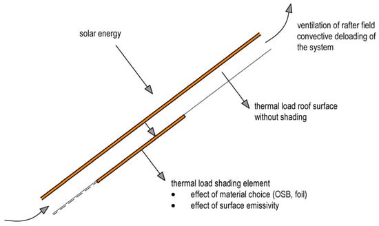
Figure 1.
Chart of studied effects on a roof.
2. Materials and Methods
Experiments were conducted in a barn built in the 1950s, located in Bad Goisern, Upper Austria, during August 2025. The barn features a gable roof oriented from north to south with a pitch of 37 degrees, forming part of a wooden skeleton structure. The roof is constructed with a 24 mm solid wood formwork and covered using a double-layered Eternit (fiber-reinforced concrete, Eternit Austria, Vöcklabruck, Austria) rhombus cladding. Structurally, it is a double standing purlin roof truss without a ridge purlin. The ridge is sealed with U-shaped ridge tiles, lacking an effective ridge vent. The building is situated at 47.6° N latitude and 13.6° E longitude, at an elevation of 539 m above mean sea level (Adriatic reference). The building is located in open, unshaded terrain. The attic consists of two levels with a wooden façade featuring uncovered boards for ventilation, originally designed for hay storage. Two openings at the gable wall’s highest point allow natural airflow for cross-ventilation (see Figure 2 and Figure 3).
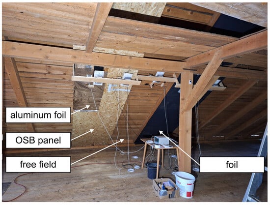
Figure 2.
View of the experimental setup inside the barn with OSB rafter field planking left (with aluminum foil), free field in the center, and underlay membrane (foil) at the right.
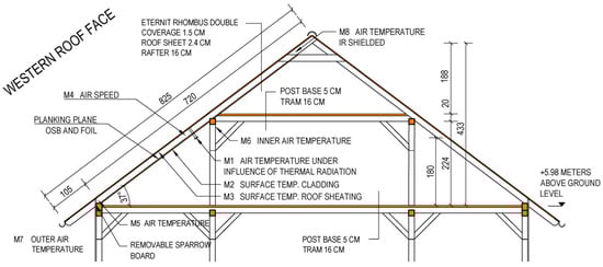
Figure 3.
Cross-section of the building with sensor positions.
For the investigation, three rafter fields on the western roof area were selected:
- (a)
- Center field: Planked with a 12 mm oriented strand board (OSB) panel (Egger, St. Johann, Austria), extending from the foot purlin to 50 cm below the first purlin, half of it coated with an emergency blanket (50 × 150 cm2, Carl Roth GmbH, Karlsruhe, Germany) coated with metallized mylin with an emissivity of 0.03 to 0.05 [24].
- (b)
- Reference field: Left unplanked to serve as a control.
- (c)
- Membrane-shielded field: Covered with a conventional under-roof membrane (Ampatop, Ampack, Götzis, Austria).
Each shielded rafter field forms a cuboid volume with a cross-sectional area of 88 × 14 cm2 and a length of 775 cm, closed at the bottom and open toward the ridge. During the measurement period, the sparrow board above the foot purlin at the cladded rafter fields was removed to allow outside air to enter the rafter field, enabling the study of ventilation effects (see Figure 3 and Table 1).

Table 1.
Overview of sensors used.
Radiative heat flux was estimated using Stefan-Boltzmann’s law (Equation (1)). For objects with temperatures below 100 °C (373.15 K), at least 97.5% of the total thermal radiation is emitted within the IR-C range (3–1000 µm), which corresponds to long-wave infrared radiation [25].
—energy emitted by thermal radiation in W/m2
—Stefan–Boltzmann constant 5.67 × 10⁻⁸ W/m2K4
—emissivity (dimensionless between 0 and 1)
—temperature of the object in K
The heat energy, which is transported via the air stream in the ventilation layer, was estimated according to Equation (2) in accordance with [20].
—heat energy transported by the airstream in W
—boundaries of the chosen time interval
—cross-sectional area in m2
—air speed in m/s
—average air density, considered with 1.118 kg/m3 (25 °C, 500 m altitude)
—average specific heat storage capacity of air; 1015 J/kgK
—air temperature at the air inlet at the foot purlin in °C
—air temperature at the air outlet at the ridge in °C
The thermal load contributed by the roof construction to the heating of the interior space was estimated using Equation (3), based on the method proposed by Aguilar-Castro et al. [9], which accounts for both convective and radiative heat transfer between the interior roof surface and the indoor environment.
—energy transfer to the interior by convective and radiative effects in W/m2
—interior convective heat transfer coefficient, estimated with 5.0 W/m2K [26]
—surface temperature of the roof inside in K
—temperature of the ambient interior air in K
—Stefan-Boltzmann constant 5.67 × 10⁻⁸ W/m2K4
—emissivity (dimensionless between 0 and 1)
—surface temperature of construction elements (column at measuring point M6) in the attic in K
Thermal images for this study were captured using a Testo 975 thermal camera (Testo, Hochschwarzwald, Germany), featuring an infrared resolution of 320 × 240 pixels and a spectral range of 7.5–14 µm. Image analysis was performed using the IRSoft software, version 5.2 (Testo, Hochschwarzwald, Germany).
Measurements of air temperature, surface temperature, and air velocity were taken at designated positions as shown in Figure 3 and detailed in Table 1. Surface temperatures at positions M2 and M3 were recorded to assess the thermal load of heated surfaces. Air temperature at the eave (M5) and ridge (M8), along with air velocity at M4, was measured to determine the energy uptake of the ventilation stream. As preliminary measurements have shown [12], the sensors are each influenced by the long-wave infrared radiation emitted by surrounding elements. To evaluate the influence of infrared radiation on temperature sensor readings at measurement point M1, two configurations were used. In both cases, the sensors were housed in polystyrene insulation boxes with the roof-facing side left open. One sensor was wrapped in reflective aluminum foil (Carl Roth GmbH, Karlsruhe, Germany, ε = 0.03 to 0.05) to minimize emissivity, while the other was covered with thin black paper to maximize emissivity (ε = 0.90). This setup enabled a comparative assessment of IR radiation effects on the measurements.
At measurement position M8, the air temperature sensors were placed inside an aluminum-coated cardboard tube (axially oriented in flow direction) to minimize the influence of thermal radiation on the readings. At the other measurement points, aluminum-bodied sensors with low emissivity were used to further reduce radiative heat input.
3. Results and Discussion
3.1. Climatic Conditions and Thermal Performance of the Construction
The measurement was conducted in August 2025 in a single building, and the results are therefore limited to the summer period and the specific building with a steep gable roof and ridge orientation North–South. Consequently, the findings of this study should be interpreted within the constraints of this experimental setup.
During the measurement period, the average outside temperature was 19.5 °C (SD 5.4 °C), while indoors, it averaged 22.1 °C (SD 5.4 °C). The highest outside temperature, 32.6 °C, occurred on 13 August at 17:26, followed by an indoor peak of 32.9 °C at 18:00 (Figure 4). From then, the outside declined at an average rate of 1.3 °C per hour, reaching 16.9 °C by 6:00 the next day. The interior temperature declined more gradually—likely due to the thermal mass of the construction elements [27]—at an average rate of 1.0 °C per hour, reaching a minimum of 20.2 °C at 7:00 pm the next day.
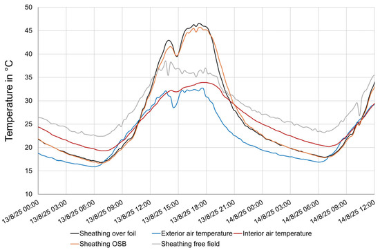
Figure 4.
The thermal behavior of construction being dependent on outside temperature.
The inner surface temperature of the roof sheathing, a key structural component in this study, closely follows the profile of the outside air temperature. The sheathing without IR shielding peaks at 37.7 °C at 2:30 pm, remaining approximately constant until 6:00 pm. The top temperature is in accordance with a study measuring 44.1 °C at the bottom of wooden shingles in Madison, Wisconsin [28]. This results in a daily temperature amplitude of about 15 °C on sunny mid-August days. The peak of the temperature curve (gray in Figure 4) appears truncated, likely due to increased heat radiation efficiency at higher temperatures. This radiated energy contributes to the warming of the rooms below [29].
The sheathing in the IR-shielded rafter fields (black and orange lines in Figure 3) exhibits a more pronounced temperature profile on the same day, with an average temperature of 29 °C and a peak of 46 °C at 5:00 pm. Sheathing temperature is nearly identical for OSB and foil shielding. The higher values compared to the unshielded field are attributed to reduced heat radiative and convective heat transfer to underlying construction elements due to the shielding.
The interior surface temperature of the IR shielding elements, shown as dashed lines in Figure 5, generally follows the temperature pattern of the sheathing above. Both the OSB panel and foil exhibit similar temperatures, peaking at 31 °C at 5:00 pm on August 26th. The only notable difference between the shielding materials is that the OSB panel exhibits slightly slower thermal response due to its higher mass. During peak temperatures (2:00–8:00 pm), the surface temperature of the OSB panel coated with aluminum foil is, on average, 1 °C higher than the uncoated panel. This suggests reduced heat radiation from the aluminum-coated surface.
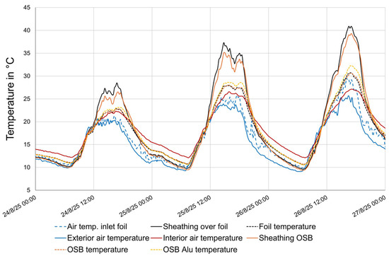
Figure 5.
The temperature of the IR shielding layers being dependent on thermal boundary conditions.
3.2. Air Speed in the Rafter Fields
As known from earlier research [12,22], the effectiveness of IR shielding elements in the context of the present study strongly depends on efficient ventilation within the rafter field. This study confirms that the upward airflow in the rafter fields is driven by the heating of air caused by the hot roof surface (Figure 6). On 26 August, airflow in the foil-cladded rafter field was low overnight (0.18 m/s, SD = 0.11) until 7:00 am. During the day, it rose with the outdoor temperature, averaging 0.38 m/s (SD = 0.21) between 7:00 am and 8:00 pm. This exceeds theoretical buoyancy-based estimates [20]. The variability indicates that shorter logging intervals may improve future analyses. In the OSB-cladded rafter field, the average airspeed during this period is 0.28 (SD = 0.14) m/s. The average air speed in the foil-clad field is statistically significantly (t-test, α = 0.01) higher than in the OSB-clad field. In the uncladded reference field, at this time with a closed sparrow board at the foot purlin, the average airspeed is 0.16 m/s (SD = 0.11 m/s). The airspeed measured is significantly lower than determined in experimental cavities of ribbed and flat roofing panels, but the authors point out that the air speed increases with the temperature gradient between inlet and outlet [20].
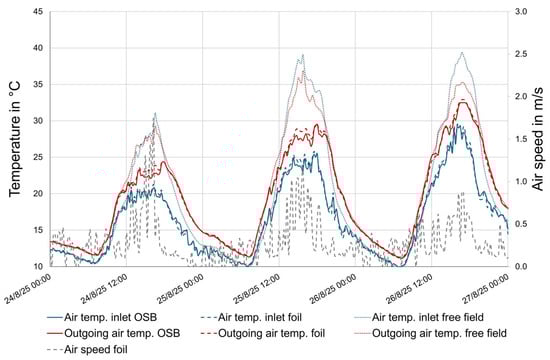
Figure 6.
Air temperature and air speed measured in rafter fields.
Comparing inlet (foot purlin) and outlet (ridge) air temperatures reveals heat uptake. In the unshielded reference field, despite confirmed airflow, outlet and inlet temperatures were nearly identical (blue and red dotted lines, Figure 6). Occasional periods where outlet air was cooler likely reflect attic thermal buoyancy. The relatively high airspeed without cladding suggests a convective roll. At low Rayleigh numbers, attic flow remains laminar and symmetric, becoming unstable as Rayleigh numbers increase [30].
The OSB-cladded field shows a significant temperature difference between the air inlet (solid blue line) and outlet (solid red line), with the outlet air being on average 2.9 °C warmer—indicating heat absorption from the surrounding construction elements [31]. In contrast, the foil-cladded field exhibits a smaller temperature difference, with the outlet air averaging 2.5 °C warmer than the inlet. This is likely due to a slightly higher air exchange rate in the rafter field and the lower heat storage capacity of the foil compared to the OSB panel. In all cases, temperature differences become more pronounced as overall temperature levels rise.
As illustrated in Figure 5, the temperature difference between incoming air at the eave and outgoing air at the ridge remains consistently positive throughout a hot day such as 26 August. This indicates a continuous transfer of heat from the roof structure into the ventilated air stream. For the rafter field equipped with the foil, the extracted thermal energy on that day amounts to approximately 2.8 kWh. On the hottest day of the measurement period, 13 August, the energy removed reaches 3.8 kWh. This is in the range of values determined for comparable slopes in an experimental situation adapted for the lower thermal gradient of the current study [20].
When extrapolated to the entire roof surface, these values highlight the considerable potential of ventilated roof systems to mitigate overheating in buildings [20]. The results underscore the effectiveness of passive ventilation strategies in enhancing thermal comfort and reducing cooling loads, particularly under high solar radiation conditions. In this respect, the study confirms the findings of Campaniço et al. [32], who pointed out that direct ventilation systems can save up to 13 kWh/m2 over the summer period. In August 2025, the temperature gradient in the studied roof cavity was negative only 1.1% of the time, indicating that the cooling effect of ventilation was consistently present throughout the month. Provided that no other building physics considerations oppose it, it would be reasonable to close the ventilation cavities between the rafters during winter in order to minimize thermal losses and reduce the cooling of the structure [21].
3.3. Thermal Load of Interior Roof Surfaces
On 26 August, moderate conditions (max indoor air temperature 27 °C) provided an ideal setting to assess radiative heat transfer from roof surfaces. Despite the absence of extreme summer heat, all experimental configurations demonstrated measurable radiative heat input, evidenced by elevated temperatures beneath the roof surface compared to the ambient indoor air temperature (see Figure 7). Thermal load was estimated using shielded air temperature sensors oriented toward the roof surface, as detailed in Section 2.
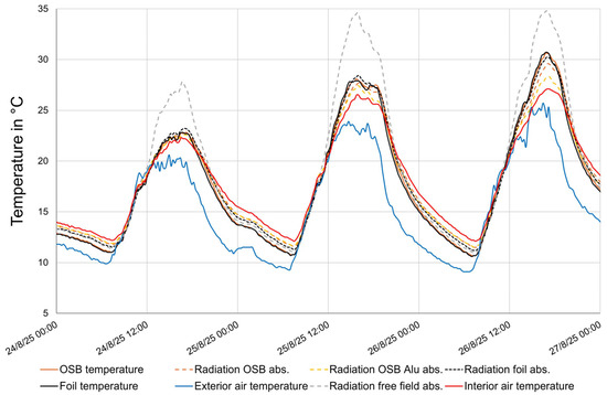
Figure 7.
Roof surface heat radiation estimated from the air temperature beneath.
Air temperature analysis in test enclosures with high-emissivity (IR-absorptive) surfaces facing the roof revealed notable thermal gradients. The highest value, 34.7 °C, occurred beneath the uninsulated rafter field, which was 7.6 °C above room temperature. In comparison, peak temperatures beneath the IR-absorbing foil and OSB-cladded fields were 30.2 °C and 29.5 °C, respectively. The aluminum-coated OSB panel showed a 1.2 °C lower peak at point M1 than uncoated OSB, confirming the effectiveness of low-emissivity surfaces in reducing radiative heat transfer.
Figure 8 presents temperature profiles beneath heated roof surfaces between 14:00 and 20:00 on 26 August, comparing sensors shielded with aluminum foil (serving as an IR reflective reference with minimized radiative input) against those exposed to high-emissivity surfaces. The magnitude of the temperature differential between shielded and unshielded sensors serves as an indicator of radiative heat input. Peak temperature differences were observed as follows: 5.2 °C in the reference field, 1.9 °C beneath the foil, 1.5 °C beneath the OSB panel, and 0.6 °C beneath the aluminum-coated OSB panel. These results substantiate the role of aluminum foil in reducing IR radiation exposure (Figure 9).
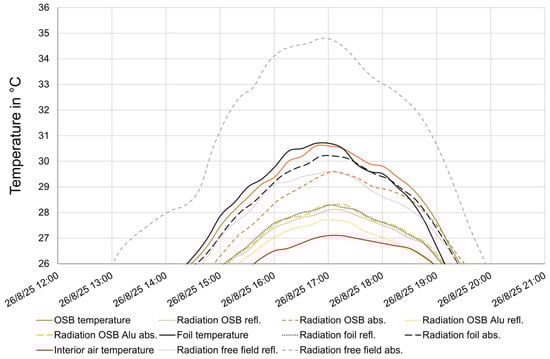
Figure 8.
Estimated roof heat radiation from air temperature beneath on a hot August afternoon, 2025.
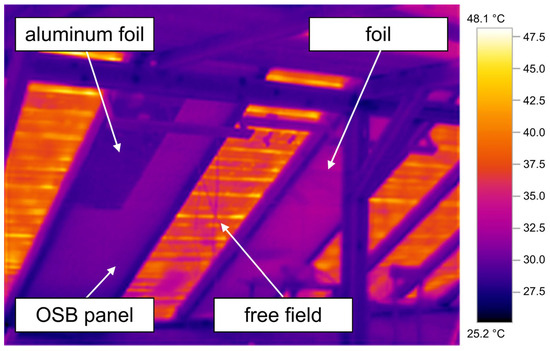
Figure 9.
Thermography of the experimental situation, 8 August, 11.30 pm, 29 °C reflected temperature, surface temperature OSB panel with aluminum foil on the left 31.7 °C, OSB panel 31.0 °C.
For the same time period (26 August, 2 to 8 pm), the average thermal load of the western roof area according to Stefan-Boltzmann (Equation (3)) is 23 W/m2 with the foil, 25 W/m2 with the OSB, 41 W/m2 with the uncladded roof, and 19 W/m2 with the aluminum-coated OSB panel. In most cases, loads beneath OSB were lower than beneath foil. This is in accordance with the previous study [12] and findings substantiating the role of effectively deloading the IR shield (or radiant barrier) itself [15]. On 26 August, however, OSB temperature slightly exceeded foil, likely due to thermal storage after three hot days.
OSB panels consistently outperformed foil membranes, reducing thermal loads by approximately 40%. Adding a low-emissivity layer further improved performance to more than 50%, confirming emissivity as a key design parameter (Table 2). These values require direct measurement, which is challenging in the long-wave IR range, but they indicate a clear path for developing interior IR shielding systems.
Table 2.
Overview of the calculated thermal loads as average for 26 August between 2 am and 8 pm—based on measurement of surface temperatures (standard deviation in brackets).
Although aluminum-coated OSB showed a surface temperature 0.7 °C higher than uncoated OSB, thermal imaging revealed a cooler appearance. This is due to reduced radiative emission from the low-emissivity aluminum surface, limiting IR transfer despite higher temperatures. Similar findings in energy-efficient homes show radiant barriers can reduce cooling loads to 15 % of nominal demand during hot seasons [33].
On 26 August, the attic experienced continuous heat gain from midnight until 21:00. For most of this period, convective and radiative heat transfer were balanced. When surface temperatures exceeded 20 °C, radiation became dominant. This trend, predicted by Equation (3), was confirmed by sensor data comparing IR-reflective and IR-absorbing setups. Due to the low intensity of radiation at lower temperatures, IR-reflective coatings are unlikely to significantly hinder heat gains during winter [15].
4. Conclusions
Conclusions drawn from this study are
- For heritage buildings, optimized IR shields combining OSP panels with low-emissivity coatings offer a practical solution for reducing summer heat loads without altering exterior appearance (e.g., heritage-protected architecture).
- The cooling potential of ventilated rafter cavities during a Central European summer is considerable. The findings are particularly relevant for roof surfaces exposed to intense solar radiation, and future research should adopt a broader, international perspective.
- All test configurations showed elevated temperatures beneath the roof compared to indoor air. Surfaces with low emissivity, particularly aluminum-coated OSB panels, significantly reduced radiative heat input, confirming their effectiveness in mitigating thermal loads even without extreme summer heat.
- The present findings are constrained by the summer observation period and the characteristics of a single building. Future research should encompass year-round measurements and include buildings with diverse roof slopes and roof orientations to enhance the generalizability and practical relevance of the results.
Author Contributions
Conceptualization, G.K. and F.I.; methodology, G.K.; software, G.K.; validation, G.K., F.I. and L.K.; formal analysis, G.K.; investigation, G.K. and F.I.; resources, G.K., F.I. and L.K.; data curation, G.K.; writing—original draft preparation, G.K.; writing—review and editing, F.I. and L.K.; visualization, G.K.; supervision, F.I.; project administration, G.K. and F.I.; funding acquisition, G.K., F.I. and L.K. All authors have read and agreed to the published version of the manuscript.
Funding
This research was funded by the Austrian Federal Ministry for Housing, Arts, Culture, Media, and Sport, by ICOMOS Austria and by the Ministry of Education, Science, Research and Sport of the Slovak Republic under the project VEGA 1/0077/24.
Data Availability Statement
The data presented in this study are available on request from the corresponding author due to data complexity.
Acknowledgments
The authors gratefully acknowledge Alfons Huber for his valuable contribution to this work. With a long-standing research background in the physical principles of low-tech buildings, he provided key encouragement for the exploration of infrared shading elements.
Conflicts of Interest
The authors declare no conflicts of interest.
References
- Omle, I.; Kovács, E.; Bolló, B. Applying recent efficient numerical methods for long-term simulations of heat transfer in walls to optimize thermal insulation. Results Eng. 2023, 20, 101476. [Google Scholar] [CrossRef]
- Heider, J.; Conrad, N.; Stark, T.; Abdulganiew, A.; Kosack, P.; Wagner, A.-K. Forschungsprojekt “IR-Bau”: Potential von Infrarot-Heizsystemen für Hocheffiziente Wohngebäude; Fraunhofer IRB: Konstanz, Germany, 2020. [Google Scholar]
- Dabaieh, M.; Wanas, O.; Hegazy, M.A.; Johansson, E. Reducing cooling demands in a hot dry climate: A simulation study for non-insulated passive cool roof thermal performance in residential buildings. Energy Build. 2015, 89, 142–152. [Google Scholar] [CrossRef]
- Synnefa, A.; Santamouris, M.; Apostolakis, K. On the development, optical properties and thermal performance of cool colored coatings for the urban environment. Sol. Energy 2007, 81, 488–497. [Google Scholar] [CrossRef]
- Suehrcke, H.; Peterson, E.L.; Selby, N. Effect of roof solar reflectance on the building heat gain in a hot climate. Energy Build. 2008, 40, 2224–2235. [Google Scholar] [CrossRef]
- Ziaeemehr, B.; Jandaghian, Z.; Ge, H.; Lacasse, M.; Moore, T. Increasing Solar Reflectivity of Building Envelope Materials to Mitigate Urban Heat Islands: State-of-the-Art Review. Buildings 2023, 13, 2868. [Google Scholar] [CrossRef]
- de Brito Filho, J.P.; Henriquez, J.R.; Dutra, J. Effects of coefficients of solar reflectivity and infrared emissivity on the temperature and heat flux of horizontal flat roofs of artificially conditioned nonresidential buildings. Energy Build. 2011, 43, 440–445. [Google Scholar] [CrossRef]
- Sabzi, D.; Haseli, P.; Jafarian, M.; Karimi, G.; Taheri, M. Investigation of cooling load reduction in buildings by passive cooling options applied on roof. Energy Build. 2015, 109, 135–142. [Google Scholar] [CrossRef]
- Aguilar-Castro, K.M.; Cerino-Isidro, J.L.; Torres-Aguilar, C.E.; May Tzuc, O.; Macias-Melo, E.V.; Serrano-Arellano, J. Effect of interior and exterior roof coating on heat gain inside a house. Constr. Build. Mater. 2024, 454, 139045. [Google Scholar] [CrossRef]
- Mohamed, H.I.; Lee, J.; Chang, J.D. The Effect of Exterior and Interior Roof Thermal Radiation on Buildings Cooling Energy. Procedia Eng. 2016, 145, 987–994. [Google Scholar] [CrossRef]
- Escudero, C.; Martin, K.; Erkoreka, A.; Flores, I.; Sala, J.M. Experimental thermal characterization of radiant barriers for building insulation. Energy Build. 2013, 59, 62–72. [Google Scholar] [CrossRef]
- Kain, G.; Idam, F.; Kristak, L. Infrared (IR) Shading as a Strategy to Mitigate Overheating in Traditional Buildings. Buildings 2025, 15, 3471. [Google Scholar] [CrossRef]
- Miranville, F.; Boyer, H.; Lauret, P.; Lucas, F. A combined approach for determining the thermal performance of radiant barriers under field conditions. Sol. Energy 2008, 82, 399–410. [Google Scholar] [CrossRef]
- Ferreira, M.; Corvacho, H. The effect of the use of radiant barriers in building roofs on summer comfort conditions—A case study. Energy Build. 2018, 176, 163–178. [Google Scholar] [CrossRef]
- Lee, S.W.; Lim, C.H.; Salleh, E.I.B. Reflective thermal insulation systems in building: A review on radiant barrier and reflective insulation. Renew. Sustain. Energy Rev. 2016, 65, 643–661. [Google Scholar] [CrossRef]
- Medina, M.A.; Young, B. A perspective on the effect of climate and local environmental variables on the performance of attic radiant barriers in the United States. Build. Environ. 2006, 41, 1767–1778. [Google Scholar] [CrossRef]
- Stevens, T.R.; Parsi, B.; Mulford, R.B.; Crane, N.B. Dynamic Radiant Barrier for Modulating Heat Transfer and Reducing Building Energy Usage. Energies 2024, 17, 3959. [Google Scholar] [CrossRef]
- Ye, X.; Chen, Y.; Sheng, J.; Wang, W. An overview of climate change adaptation and mitigation research in architecture heritage. Energy Build. 2025, 351, 116680. [Google Scholar] [CrossRef]
- Idam, F.; Kain, G. Neo-ecological Approaches to Solving the Construction Crisis. CERJ 2025, 15, 555913. [Google Scholar] [CrossRef]
- Lee, S.; Park, S.H.; Yeo, M.S.; Kim, K.W. An experimental study on airflow in the cavity of a ventilated roof. Build. Environ. 2009, 44, 1431–1439. [Google Scholar] [CrossRef]
- Kain, G.; Idam, F.; Federspiel, F.; Réh, R.; Krišťák, Ľ. Suitability of Wooden Shingles for Ventilated Roofs: An Evaluation of Ventilation Efficiency. Appl. Sci. 2020, 10, 6499. [Google Scholar] [CrossRef]
- Gagliano, A.; Patania, F.; Nocera, F.; Ferlito, A.; Galesi, A. Thermal performance of ventilated roofs during summer period. Energy Build. 2012, 49, 611–618. [Google Scholar] [CrossRef]
- Quevedo, T.C.; Melo, A.P.; Lamberts, R. Assessing cooling loads from roofs with attics: Modeling versus field experiments. Energy Build. 2022, 262, 112003. [Google Scholar] [CrossRef]
- Zhao, M.; Zhu, H.; Qin, B.; Zhu, R.; Zhang, J.; Ghosh, P.; Wang, Z.; Qiu, M.; Li, Q. High-Temperature Stealth Across Multi-Infrared and Microwave Bands with Efficient Radiative Thermal Management. Nanomicro. Lett. 2025, 17, 199. [Google Scholar] [CrossRef]
- Marek, R.; Nitsche, K. Praxis der Wärmeübertragung; Carl Hanser: Leipzig, Germany, 2012. [Google Scholar]
- Awbi, H.B. Calculation of convective heat transfer coefficients of room surfaces for natural convection. Energy Build. 1998, 28, 219–227. [Google Scholar] [CrossRef]
- Cheng, V.; Ng, E.; Givoni, B. Effect of envelope colour and thermal mass on indoor temperatures in hot humid climate. Sol. Energy 2005, 78, 528–534. [Google Scholar] [CrossRef]
- Winandy, J.E.; Barnes, H.M.; Falk, R.H. Summer temperatures of roof assemblies using western redcedar, wood-thermoplastic composite, or fiberglass shingles. For. Prod. J. 2004, 54, 27–33. [Google Scholar]
- Al-Sanea, S.A. Thermal performance of building roof elements. Build. Environ. 2002, 37, 665–675. [Google Scholar] [CrossRef]
- Saha, S.C.; Khan, M. A review of natural convection and heat transfer in attic-shaped space. Energy Build. 2011, 43, 2564–2571. [Google Scholar] [CrossRef]
- Ciampi, M.; Leccese, F.; Tuoni, G. Energy analysis of ventilated and microventilated roofs. Sol. Energy 2005, 79, 183–192. [Google Scholar] [CrossRef]
- Campaniço, H.; Hollmuller, P.; Soares, P.M. Assessing energy savings in cooling demand of buildings using passive cooling systems based on ventilation. Appl. Energy 2014, 134, 426–438. [Google Scholar] [CrossRef]
- Hageman, R.; Modera, M.P. Energy savings and HVAC capacity implications of a low-emissivity interior surface for roof sheathing. In Proceedings of the 1996 ACEEE Summer Study on Energy Efficiency in Buildings, Pacific Grove, CA, USA, 25–31 August 1996; pp. 1.117–1.130. [Google Scholar]
Disclaimer/Publisher’s Note: The statements, opinions and data contained in all publications are solely those of the individual author(s) and contributor(s) and not of MDPI and/or the editor(s). MDPI and/or the editor(s) disclaim responsibility for any injury to people or property resulting from any ideas, methods, instructions or products referred to in the content. |
© 2025 by the authors. Licensee MDPI, Basel, Switzerland. This article is an open access article distributed under the terms and conditions of the Creative Commons Attribution (CC BY) license (https://creativecommons.org/licenses/by/4.0/).