Abstract
The synthesis and electrocatalytic properties of amorphous first- and third-row transition metal sulfides (a-TMS) for green hydrogen generation have been comprehensively reviewed. These electrocatalysts can be prepared by several solution processes, including chemical bath deposition, electrodeposition, sol–gel, hydrothermal reaction and thermolysis. The deposition method strongly influences the electrochemical properties of the synthesized a-TMS electrocatalyst. Based on overpotential at 10 mA/cm2, the electrocatalytic activity of mono-metallic a-TMS for hydrogen evolution is ranked as follows: a-NiSx > a-CuSx > a-CoSx > a-WSx > a-FeSx. The best performing a-NiSx prepared by chemical bath deposition has an overpotential at 10 mA/cm2 of 53 mV and Tafel slope of 68 mV/dec in 1 M KOH electrolyte. The integration of Ni into the a-TMS network structure is crucial to achieving high activity in multi-metallic a-TMS electrocatalyst, as demonstrated by the bifunctional (NiFe)Sx/NiFe(OH)y nanocomposite catalyst. The critical role of Ni in a-TMS catalyst design can be attributed to the lower free energy change for hydrogen adsorption on Ni. Finally, the emerging catalyst design strategy of amorphous–crystalline heterostructures with a three-dimensional morphology will be discussed together with the need to identify hydrogen adsorption sites on a-TMS electrocatalysts in future.
1. Introduction
Hydrogen, an earth-abundant chemical element, has several useful properties that make it a critical component in the challenging transition towards a decarbonized energy infrastructure comprising renewable energy sources and energy storage [1,2]. Molecular hydrogen (H2) is a colorless gas with a specific energy density of 140 MJ/kg, which is four times higher than diesel and the lithium-ion battery [3]. The high specific energy density is due to the low relative atomic mass of hydrogen and the H-H covalent bond dissociation energy of 435.9 kJ/mol [4]. When oxidized by combustion in air or by reaction with molecular oxygen (O2) in a fuel cell, the chemical energy in H2 is converted to heat and electricity, respectively, and only water is produced as the reaction product [4]. These attributes make H2 an attractive energy carrier and storage medium for mitigating the uncertainty in supply in an electricity grid with a high proportion of intermittent renewable energy sources (Figure 1). The large-scale generation of H2 from renewable energy sources such as solar farms and wind farms can also facilitate the decarbonization of steel, chemical, cement manufacturing and the transportation industry, such as heavy goods vehicles and marine shipping [5]. For heavy industries that are difficult to electrify, H2 is really the only alternative to fossil fuels as a source of sustainable energy [6].
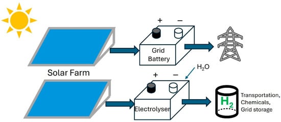
Figure 1.
Schematic diagram of renewable electricity from a solar farm being stored in grid-connected rechargeable batteries or in green hydrogen.
Hydrogen is already produced on an industrial scale as a feedstock chemical for the synthesis of ammonia for manufacturing fertilizer and for refining petrochemicals. However, the present steam methane (CH4) reforming process for making H2 uses CH4 from natural gas as both a reactant and as a fuel to heat the methane and steam mixture to the high temperatures required for H2 and CO2 formation [7]. Both the steam methane reforming reaction and the combustion release large amounts of CO2, which is the main greenhouse gas causing global warming. It has been reported that the current method of H2 production results in annual CO2 emission equal to the combined emissions of Indonesia and the United Kingdom [3]. In another life cycle assessment study using the ecoinvent database, Eryazici et al. estimated that in 2019, the global chemical industry emitted about 2.6 billion tons of CO2 equivalent into the atmosphere, of which 42% is direct emission [8]. A significant portion of this direct emission is due to hydrogen generation from the steam methane reforming process for ammonia production [8]. Since the purity of H2 produced by the methane steam reforming method is also not high, there is a need for an alternative method that is both economical and environmentally friendly.
The most promising carbon neutral process to produce H2 is to use water electrolysis or electrochemical water splitting (EWS) powered by renewable electricity such as solar and wind [9,10]. Hydrogen produced by this method is often referred to as green H2 [11]. The other color designations of H2 are gray for H2 produced from fossil fuels and blue for H2 produced from fossil fuels with carbon capture and storage [11]. Interestingly, the EWS method driven by hydropower was in fact the main H2 production process from 1927 to 1990, before the advent of the cheaper steam methane reforming process [12]. Although the EWS method is mature and well established, the amount of green H2 produced in 2022 was a paltry 109 kilotons or 0.11% of the 95 million metric tons of H2 produced that year [13]. There are also few reports on solar- or wind-driven EWS systems in the literature [14]. As mentioned recently in ref. [15], this shortfall in green H2 generation is due to three reasons. First, the proton exchange membrane (PEM) electrolyzer, which is at present the only mature EWS system tolerant of intermittent supply voltages, operates in highly acidic conditions [16]. These conditions can corrode the electrodes and their coatings. As a result, noble metals from the platinum (Pt) group and their oxides such as Pt and iridium dioxide (IrO2) are currently used as electrocatalysts to accelerate the kinetics of the hydrogen evolution reaction (HER) at the cathode and the oxygen evolution reaction (OER) at the anode. These scarce metals are, however, very expensive and limited in supply, making the upscaling of green H2 production by PEM electrolyzers impractical. The other two limiting factors for green H2 production by EWS are the need to develop highly durable ion conducting membranes which are not based on fluoropolymers and new electrolyzer designs that are compatible with intermittent renewable power sources [15]. In this article, the focus will be on the development of earth-abundant HER electrocatalysts in EWS systems.
In recent years, many types of earth-abundant HER electrocatalysts based on mono- or multi-transition metal (TM) compounds have been actively investigated for the EWS application [17]. These include TM borides, carbides, phosphides, sulfides and selenides. A comprehensive review of these main categories of crystalline earth-abundant HER electrocatalysts has been published [18]. The TMSs are especially promising because they are highly effective for HER and sulfur is an abundant chemical element [19,20]. The TMS compounds are also the only category of HER electrocatalysts that mimic the catalytic sites in the hydrogenase and nitrogenase enzymes in microorganisms for the biological production and splitting of H2 [21]. A major recognition in the field of earth-abundant electrocatalysts in recent years is that the bulk and nanocrystalline form of TM compounds are less effective than their amorphous (non-crystalline) counterparts. This is because the short-range order in amorphous catalytic materials results in many structural defects such as uncoordinated atoms, which can act as active adsorption sites for HER [22,23]. In this article, we focus on recent developments in the synthesis, deposition and characterization of amorphous TMS HER electrocatalysts. Amorphous metal sulfides derived from the first and third rows of the TM series will be covered first, including mono-metallic and multi-metallic TMS compounds. Since amorphous nickel sulfide (a-NiSx)- and Ni-containing a-TMS compounds have the best overall electrocatalytic properties for the HER at present, emphasis will be placed on developments in these materials. A theoretical explanation for the important role of Ni in these a-TMS electrocatalysts will also be provided in Section 4. Amorphous TMS from the second row are not discussed in detail because there had been multiple prior reviews on amorphous molybdenum sulfide (a-MoSx), and amorphous ruthenium sulfide (a-RuSx) is not earth-abundant [24,25,26,27]. Instead, we use a-MoSx as the benchmark amorphous electrocatalyst to evaluate the performance of TMS electrocatalytic materials from the first and third row of the transition metal series. Comparison will also be made wherever possible with the crystalline counterpart of a first- or third-row amorphous TMS. This article will conclude with an outlook on the search strategy for promising amorphous TM sulfides from the third-row TM elements.
2. EWS Reactions and the Role of Electrocatalysts
The overall EWS reaction is simple and can be written as Equation (1) [28]:
This reaction is strongly endothermic with an enthalpy change of 285.84 kJ/mol at the standard conditions of 298.15 K and 1 atm pressure. Thus, energy input is needed for EWS to occur. The theoretical equilibrium thermodynamic applied potential for Equation (1) is 1.23 V [28]. This is the minimum voltage required for EWS, and the actual applied potential with acceptable H2 generation rates will be higher due to ohmic and other losses. In an EWS electrolyzer, the above redox reaction takes place via two concurrent half-cell reactions (HER and OER) at the cathode/electrolyte and anode/electrolyte interfaces, respectively. Despite decades of investigation, the detailed reaction mechanism of the HER and OER is not fully understood and are somewhat controversial, especially for the more complicated OER [29]. However, it is generally agreed that the EWS mechanism depends on the pH condition within the electrolyzer. For acidic conditions such as those in the PEM electrolyzer, the three steps of the HER are as follows [17]:
This mechanism is essentially a 2-electron reduction process (Figure 2). In the Volmer step of Equation (2), protons originated from the oxidation of water at the anode traverse the PEM to reach the cathode. After adsorption at active catalytic sites on the electrocatalyst surface, these protons are reduced and become adsorbed atomic hydrogen H* (the asterisk * is used to designate an adsorption site on a heterogeneous catalyst in these equations). The adsorbed H* can form H2 by either the Heyrovsky step or the Tafel step. In the former (Equation (3)), H* reacts with a reduced proton, while in the latter (Equation (4)), two proximate adsorbed hydrogen atoms combine to form a H2 molecule. It is important to note that all three steps require active adsorption sites on the catalyst surface, which ideally should not undergo any chemical change during EWS.
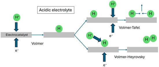
Figure 2.
Schematic diagram of the Volmer, Heyrovsky and Tafel steps in the HER of water electrolysis in acidic electrolytes. All three steps involve catalytic sites on the cathode electrocatalyst.
In the alkaline water electrolyzer (AWE) and the more recent anion exchange membrane (AEM) electrolyzer [30], the three steps of the HER can be written as follows [17]:
In alkaline and neutral conditions, water molecules are reduced at the cathode to form H* (Figure 3), and the OH− ions present either in the electrolyte or transit through the anion exchange membrane are oxidized at the anode to O2. Note that Equations (5)–(7) also involve the participation of active sites on the catalyst surface.
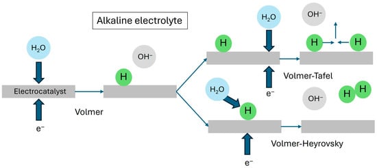
Figure 3.
Schematic diagram of the Volmer, Heyrovsky and Tafel steps in the HER of water electrolysis in alkaline electrolytes.
For the OER, there are currently two proposed models for the reaction mechanism. In the conventional adsorbate evolution mechanism [31], the OER involves a series of four coordinated proton electron transfer (CPET) reactions that are also dependent on pH conditions. For acidic electrolytes, the CPET reactions can be written as follows:
For alkaline electrolytes, the reaction steps are the following:
In Equations (8)–(15), O*, HO* and HOO* are reaction intermediates that are adsorbed on the electrocatalyst surface. Since the focus of this article is HER, we refer the reader to refs. [31,32] for the lattice oxygen-mediated mechanism for OER. Ref. [32] also includes an excellent review of a-TM OER electrocatalysts.
The slowest step(s) in Equations (2)–(7) determines the rate of the water splitting reaction and is termed the rate-determining step. This step in the reaction mechanism for a HER electrocatalyst can in principle be deduced from the slope of the Tafel plot, which is a semi-logarithmic plot of the Tafel equation [18]:
In Equation (16), h is the overpotential, a is an intercept parameter, b is the Tafel slope and j is the stabilized current density at overpotential h. The Tafel equation can be derived from the fundamental Butler–Volmer equation of electrochemistry and is discussed in detail in [33]. The Tafel slope , where R is the molar gas constant, T is the absolute temperature, b is the electron transfer coefficient (or asymmetry parameter), n is the number of moles of electrons and F is Faraday’s constant. According to the classical theory for HER [34,35], the value of b for a rate-determining Volmer, Heyrovsky and Tafel step at room temperature should be 4.6 RT/F (~118 mV/dec), 1.53 RT/F (~39 mV/dec) and 1.15 RT/F (~29 mV/dec), respectively. It is not trivial to deduce the rate-determining step from the Tafel plot. First, it is crucial to measure the steady state current density at a given overpotential. Second, as discussed in [36], the ideal straight line Tafel plot is only obtained when multiple experimental conditions are fulfilled. For the multi-step HER and OER, this is seldom the case. As a result, the Tafel plot can deviate from linearity. Van der Heijden et al. have recently proposed the Tafel slope plot to identify the cardinal Tafel slope for a physically meaningful Tafel slope extraction [36]. Deeper physical insight into the Tafel slope can be gained from theoretical simulations. A recent breakthrough is the microkinetic model for the HER and the reverse hydrogen oxidation reaction (HOR) on Pt(111) surfaces [37]. In their computational study, Gao and Wang used the continuum solvation density functional theory (CS-DFT) approach to calculate the potential dependent energy barriers and hydrogen coverage for all elementary reaction steps in the HER and HOR on Pt(111). In highly acidic conditions, the HER energy barriers for the Volmer–Heyrovsky path are found to be lower than the competing Volmer–Tafel path. As a result, the HER proceeds primarily via the Volmer–Heyrovsky mechanism and the Heyrovsky step is rate limiting. The calculated polarization curve based on potential dependent reaction barriers yields a computed Tafel slope of 42 mV/dec, which is close to the experimental Tafel slope of 39 mV/dec [37]. The microkinetic model demonstrates that the Tafel slope results from multiple reaction pathways rather than one reaction pathway.
The electrocatalyst used for the HER in electrolyzers serves two functions. First, by providing active sites for adsorption, it lowers the activation energy barrier for the Volmer, Heyrovsky and Tafel reactions and increases the kinetics of these reactions. Second, the electrocatalyst provides a conductive surface at which electron transfer reactions can take place readily. These two functions are especially critical for the more sluggish OER in EWS [28]. As discussed in ref. [38], there are two major mechanisms of adsorption onto the catalyst surface. In physisorption, the adsorbate is only weakly bound to the adsorption site by van der Waals’s electrostatic forces. As a result, the adsorbate can be physisorbed onto any part of the catalyst surface. On the other hand, in chemisorption, the adsorbate needs to form a chemical bond with the catalyst surface. As a result, this usually takes place at specific sites on the catalyst surface.
The desired characteristics of an earth-abundant EWS electrocatalyst include the following: (i) high electrode catalytic activity, (ii) small Tafel slope b, (iii) high Faradaic efficiency (FE), (iv) large electrode surface area, (v) high intrinsic activity at catalytic sites, (vi) durability in electrolyte with wide pH range, (vii) bifunctionality, (viii) superhydrophilicity, (ix) good adhesion to electrode support and (x) high electrical conductivity. The electrode catalytic activity is the most basic characteristic of an electrocatalyst and is usually reported as the onset overpotential of the measured polarization curve (current density–voltage) or the overpotential corresponding to a working electrode current density of 10 mA/cm2 (η10). A low onset overpotential and low η10 is desirable as they imply that an electrolyzer can operate efficiently at high current density. A small slope b in the linear portion of the Tafel plot implies fast electrode kinetics and is desirable for industrial water electrolyzers. The current density of the working electrode comprises a Faradaic component related to H2 generation and a non-Faradaic component due to non-EWS side reactions. For high FE, the Faradaic component should be the only, or dominant, cathode current component. The FE is usually determined by dividing the actual mass of H2 generated during EWS by the theoretical mass of H2 generated by the current density used and the ratio is converted to a percentage.
The Faradaic current component depends on the actual or true electrode surface area and the intrinsic catalytic activity of each catalytic site. The electrode area can be increased by using either a porous electrode such as a metal foam or a nanostructured electrocatalyst that has greater surface roughness or porosity. In addition to increasing the surface area, a porous morphology is also beneficial to mass transport. The actual surface area of the working electrode is usually determined directly by gas adsorption porosimetry or indirectly by measuring the geometric electric double layer (EDL) capacitance (Cdl), defined as the EDL capacitance (C) normalized by the geometric electrode area [39]. This is because, according to the Helmholtz theory [40], , where e0 is the permittivity of free space, er is the dielectric constant of the electrolyte, A is the electrode area and d is the thickness of the EDL. Physical insight into the EDL beyond that described by the Gouy–Chapman–Stern theory can be obtained through computational modeling. The most often used techniques are classical DFT, classical molecular dynamics and grand canonical Monte Carlo simulations [40]. In one study [41], classical DFT was used to study the effect of pore size and electrode geometry on EDL capacitance. A spherical pore-shell geometry was considered in which two concentric hollow spherical electrodes are separated by a pore-like space with variable pore size. This geometry turns into a slit pore when the inner sphere radius tends towards infinity. The simulated EDL capacitance for a pore filled with an ionic liquid showed an oscillatory dependence on both the pore size and the radius of the inner electrode.
The intrinsic activity of a catalytic site is quantitatively described by the turnover frequency (TOF), defined as the number of reactants converted into the EWS reaction product (H2) by a catalytic site per unit time [18]. TOF is an important fundamental property of an electrocatalyst. However, it is not straightforward to measure and is therefore seldom reported in the literature. One other indicator of intrinsic catalytic activity is the exchange current density j0, which can be extracted from the log|j| intercept and the gradient of the Tafel plot [18].
Since an EWS electrolyzer typically operates in strongly acidic or alkaline conditions, it is essential for any non-noble metal electrocatalyst to be chemically inert and survive the corrosive conditions during operation. The lifetime or chemical stability of an electrocatalyst can be measured by cyclic voltammetry (CV) or chronoamperometry (CA). A very useful and desirable property of EWS catalysts is bifunctionality. This refers to the use of the same catalyst material for both the HER and OER. An electrocatalyst with bifunctionality does not have the pH compatibility issues that may arise when different HER and OER electrocatalysts are used in the same electrolyzer. Once H2 has been formed on the cathode, it is important for the gas bubble to lift off from the electrode surface rapidly so that the catalyst surface can be freed for new reactants. A superhydrophilic surface with very low water contact angle or high wettability is beneficial for gas bubble removal. In addition, since the HER involves electron transfer at the surface of the electrocatalyst, good adhesion by the electrocatalyst to the electrode support and high electrical conductivity are also important requirements for an effective electrocatalyst. This rather onerous set of material requirements makes it extremely challenging to design and fabricate HER electrocatalyst materials for EWS.
3. Amorphous Mono-Metallic First-Row TMS HER Electrocatalysts
Amorphous TMS HER electrocatalysts based on nickel (Ni), cobalt (Co), iron (Fe) and copper (Cu) from the first row of the transition metal series (atomic number 21–30) have been reported [42,43,44,45,46,47,48]. Amongst these, Ni and Co show the most promising HER (and OER) electrocatalytic activity and will be discussed first.
3.1. Amorphous Nickel Sulfide
a-NiSx can be deposited by three straightforward methods in mild reaction conditions: (i) chemical bath deposition (CBD) [42], (ii) electrochemical deposition (ECD) [43] and (iii) sol–gel deposition and activation [44]. The most recent CBD method was reported by He et al. in 2022 [42]. This elegant synthesis of a-NiSx involves simply placing an Ni foam (NF) substrate in a corundum boat filled with the sulfur-containing compound 2-mercaptoethanol (HSC2H4OH). After heating the corundum boat at 150 °C (just below boiling point 151 °C) for 1 h in flowing argon, a-NiSx can be synthesized on the Ni foam.
The amorphous nature of the deposited a-NiSx was confirmed by X-ray diffraction (XRD), high resolution transmission electron microscopy (HRTEM) and selected area electron diffraction (SAED) [42]. The XRD pattern only showed peaks corresponding to the NF, and both the HRTEM image and SAED pattern showed no evidence of crystallinity. The HER performance of a-NiSx/NF synthesized by this CBD method in alkaline solution (1 M KOH) was studied by linear sweep voltammetry (LSV) with ohmic loss (iR) correction (Figure 4a). The electrocatalytic properties are shown in the first row of Table 1 together with other a-TMS electrocatalyst discussed in this article. The overpotential η10 of 53 mV versus the reversible hydrogen electrode (RHE) is approximately a factor of five lower than the η10 for bare NF [42]. The Tafel slope b has an extracted value of 68 mV/dec (Figure 4b) which is higher than that of the reference Pt/C electrode (38 mV/dec). The Cdl which is directly proportional to the electrochemical surface area (ECSA) of the a-NiSx is 62.1 mF/cm2 (Figure 4c) and is the highest amongst the amorphous TMS synthesized by CBD in this work [42]. The charge transfer resistance Rct, deduced from fitting the Nyquist plot of the frequency dependent impedance, is a measure of the resistance to charge flow across the electrode–electrolyte interface. For a-NiSx, the Rct of ~1.4 W is lower than a-CuSx and a-FeSx prepared by the same method (Figure 4d). The electrochemical stability of a-NiSx in alkaline media was determined by CV. The polarization curve measured after 3000 CV cycles did not show any difference from the initial polarization curve (Figure 4e). Similarly, the CA plot (Figure 4f) showed no significant current drop at constant voltage bias. This shows that the a-NiSx is chemically stable in alkaline electrolytes. One further important property of a-NiSx synthesized by this method is that it is bifunctional and the OER can also be effectively catalyzed by a-NiSx.
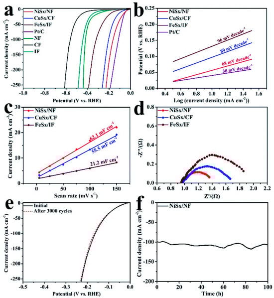
Figure 4.
(a) Polarization curves, (b) Tafel plots for a-NiSx/NF, a-CuSx/CF, a-FeSx/IF, NF, CF, IF and Pt/C in 1 M KOH, (c) double layer capacitance, (d) electrochemical impedance spectra for a-NiS/NF, a-CuSx/CF, a-FeSx/IF, (e) LSV of a-NiSx/NF before and after 3000 CV cycles, (f) CA plot for a-NiSx/NF. Used with permission of Royal Society of Chemistry, from ‘One-step synthesis of amorphous transition metal sulfides as bifunctional electrocatalysts for the hydrogen evolution reaction and oxygen evolution reaction’, W. He, F. Wang, Y. Gao, Q. Hao, C. Liu, Sustainable Energy Fuels, 6, 3852–3857, 2022 [42]; permission conveyed through Copyright Clearance Center Inc.

Table 1.
Electrochemical properties of mono-metallic a-TMS electrocatalysts and Pt/C.
Jiang et al. used the ECD method to deposit a-NiSx onto fluorine-doped tin oxide (FTO) glass [43]. A three-electrode cell comprising two FTO electrodes and an Ag/AgCl reference electrode was used for the deposition by repeated CV scans from −1.2 V to 0.2 V in the presence of nitrogen. Unlike many other studies, the HER electrocatalytic performance of the a-NiSx in neutral, acidic and alkaline pH conditions were studied comprehensively. As shown in Table 1, the measured η10 in water buffered by phosphate ions to pH 7 is 330 mV. The Tafel slope b of 77 mV/dec is amongst the smallest for non-noble metals [43]. These results show that using ECD a-NiSx, EWS can be carried out in an electrolyzer without using aqueous acids or alkalis. This is supported by an additional experiment using natural water from the Great Salt Lake in Utah U.S.A. For acidic electrolyte (0.5 M H2SO4), the h10 was measured to be 213 mV and the fitted Tafel slope was 52 mV/dec. Thus, the h10 and Tafel slope are both lower than those measured in neutral pH conditions. For 1.0 M KOH, h10 is much higher at 1140 mV and the Tafel slope is 88 mV/dec. This shows that ECD a-NiSx is not compatible with the AEM and AWE electrolyzers. Jiang et al. also determined the FE of a-NiSx by dividing the amount of H2 evolved from EWS measured by chromatography by the theoretical amount of H2 calculated from the total charge transferred in a chronopotentiometry experiment. The FE of 100% demonstrates that ECD a-NiSx is an excellent earth-abundant HER electrocatalyst for EWS in acidic electrolytes.
An important observation by Jiang et al. is that pristine a-NiSx catalyst can undergo a dynamic activation process in which the surface of the a-NiSx evolves into a more porous morphology during EWS [43]. The increase in effective surface area is confirmed by scanning electron microscopy (SEM) and Cdl measurements. Since the effective surface area is correlated with the number of catalytic sites, there is an increase in electrochemical current density during the first 10 cyclic voltammetry scans. Additional extended electrolysis experiments were conducted for both neutral laboratory and natural water and a-NiSx was shown to be stable up to 100 h.
The activation phenomenon highlighted above is the basis of another preparation method for a-NiSx, which involves synthesis of mesoporous crystalline (pyrite phase) nickel disulfide (NiS2) as a pre-electrocatalyst. A pre-electrocatalyst is a precursor material that is first deposited onto a supporting electrode. During post-deposition activation, the pre-electrocatalyst is converted into the actual HER electrocatalyst. In ref. [44], Karakaya et al. reported a sol–gel process using an aqueous mixture of nickel nitrate, thiourea (CH4N2S), cetyltrimethylammonium bromide (CTAB) and polyoxyethylene(10) lauryl ether (C12E10) surfactants to deposit mesoporous NiS2 onto FTO glass and NF substrates. After spin coating this aqueous solution onto the substrate and drying, an amorphous gel was formed. The gel was then converted into crystalline NiS2 and surfactants by heating at 185–200 °C in nitrogen. Finally, the soluble surfactants, which template the pores, are removed by dipping the films in distilled water to yield porous crystalline NiS2.
The crystallinity, composition and pore structure of the mesoporous NiS2 were confirmed by HRTEM and porosimetry characterization. The electrocatalytic properties of mesoporous NiS2 are shown in Figure 5a. During the initial set of 20 LSV scans on both FTO glass and NF substrate, a dynamic change in the polarization curves, as shown in Figure 5b,c was observed. For the NiS2/NF sample, η10 decreased during the first 20 LSV scans, as shown in Figure 5b. After an unbiased pause of 3 min, the h10 decreased further to mV before increasing again. A similar pattern can be seen for the LSV scans of the NiS2/FTO sample in Figure 5c. This evolving change in the polarization curves is attributed to a pre-catalyst behavior of mesoporous NiS2. Karakaya et al. performed detailed structural and compositional analysis of the mesoporous NiS2 at different time points of a CA experiment. This showed that when pristine mesoporous NiS2 is first used as a cathode in EWS, there is leaching of sulfur into the alkaline electrolyte because of the reduction in the disulfide S22− ion to S2− [44]. The sulfur leaching explanation is supported by the significant cathodic current observed in the first CA scan (Figure 5d), an increase in the Ni:S atomic ratio from 1:2 to 1:1 in the sample and an increase in sulfur concentration in the alkaline electrolyte. As a result of this leaching, the surface region of the electrode is converted into Ni rich a-NiSx. The reduction in porosity due to the formation of a-NiSx is evidenced by the decrease in Cdl and the Brunauer–Emmett–Teller (BET) surface area (Table 1). The reduction in porosity, however, causes the charge transfer kinetics to improve. The Rct decreases from ~62 W to 45 W after 1000 s (Table 1). A similar pre-electrocatalyst property of chemically synthesized crystalline NiS2 has also been observed earlier by Ma et al. [51]. In this work, Ni sites were identified by in situ X-ray absorption to be the main adsorption sites for HER.
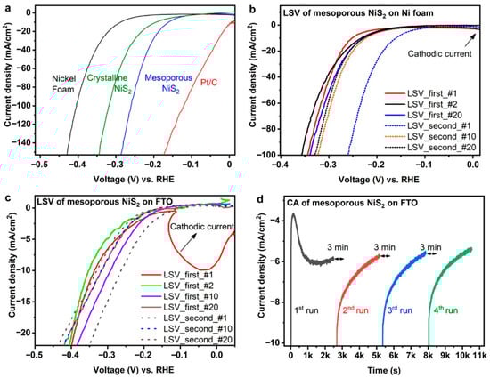
Figure 5.
(a) Polarization curves of mesoporous NiS2, crystalline NiS2, Pt/C and NF in 1 M KOH; (b) two series of 20 LSV curves for mesoporous NiS2 on NF showing dynamic behavior; (c) two series of 20 LSV curves for mesoporous NiS2 on FTO showing dynamic behavior; (d) four CA plots for mesoporous NiS2 on FTO separated by 3 min rest periods. Reprinted with permission from ACS Catal. 2020, 10, 15114–15122 [44]. Copyright 2020 American Chemical Society.
The most recent catalyst design strategy for a-NiSx is to utilize an amorphous/crystalline heterostructure approach. In ref. [45], Wang et al. used ECD to deposit a-NiSx onto an NF substrate pre-coated with CoFe layered double hydroxide (LDH) nanosheets. The CoFe LDH is a lamellar material with a staggered stacking structure. This morphology results in active sites for redox reactions and CoFe LDH has thus been studied for electrocatalyst applications [52]. However, the electrical conductivity and catalytic activity of CoFe LDH are still not adequate for HER. Hence, a-NiSx is added to enhance catalytic activity. The CoFe LDH nanosheet with a flower-like structure was prepared by hydrothermal reaction of Co, Fe containing salts, urea and NH4F in an aqueous solution at 120 °C inside an autoclave. ECD of a-NiSx onto CoFe LDH was carried out by CV in an electrochemical cell with an electrolyte comprising Ni(NO3)2 and urea. At optimal a-NiSx loading, the a-NiSx/CoFe LDH/NF heterostructure cathode in 1 M KOH has η10 = 104 mV and b = 86 mV/dec. Both parameters are better than those for a-NiSx/NF and LDH/NF and indicate good catalytic performance. A durability test by CA showed no change in current density at −0.104 V bias (versus RHE) for 24 h.
3.2. Amorphous Cobalt Sulfide
Amorphous cobalt sulfide (a-CoSx) deposition has been reported by Sun et al. using the ECD method [46]. This work pre-dated the ECD of a-NiSx by Jiang et al. [43]. The a-CoSx film was deposited from CoCl2 and thiourea dissolved in the electrolyte by repeated LSV scans between −1.2 V and 0.2 V versus Ag/AgCl in a three-electrode cell in which both working and counter electrodes were FTO glass. The electrolyte is pH7 water buffered by 1.0 M potassium phosphate. After deposition, the almost black a-CoSx/FTO film was further annealed in Ar gas at 300 °C for 2 h. The absence of long-range order in the a-CoSx film was confirmed by XRD and the Co:S atomic ratio was determined by inductively coupled plasma optical emission spectroscopy (ICP-OES) to be ~1.4 [46]. This composition was explained by the presence of CoO/Co(OH)2 impurity [46]. The HER electrocatalytic performance of a-CoSx/FTO in neutral water is shown in Table 1. Note that in this work, the reported electrocatalytic properties refer to an annealed a-CoSx film that has been subjected to EWS at constant potential for 3 h. The η10 according to the polarization curve is 167 mV and this rises to 397 mV at 50 mA/cm2. The Tafel slope deduced from the same data set is 93 mV/dec and is higher than that reported for a-NiSx, suggesting more sluggish kinetics for the HER. The FE is determined by measuring the H2 generated during a 3 h electrolysis using gas chromatography is ~100%, and the TOF is estimated to be 0.017 s−1 [46]. A further controlled potential electrolysis experiment in pH 7 water showed that the electrodeposited a-CoSx is stable for at least 40 h.
A significant limitation of ECD a-CoSx is that it is unstable in strongly acidic electrolytes. In the study by Sun et al. [46], the a-CoSx catalyst film showed rapid deactivation during the first 15 scans of the polarization curve for 0.5 M H2SO4 electrolyte. This is due to dissolution of the a-CoSx and hence this material is not suitable for applications in the PEM electrolyzer. On the other hand, a-CoSx is stable in KOH electrolyte, as demonstrated by a 25-hr CA experiment. Hence, a-CoSx may have application in both the AWE and AEM electrolyzers.
The bifunctional electrocatalytic property of a-CoSx was first reported by Liu et al. in 2017 [47]. In this work, a-CoSx with embedded Cu clusters (Cu@CoSx) was deposited by CBD directly onto CF by adding Co salt, thioacetamide and CF into ethanol at 70 °C. The CF support serves as a source of Cu atoms in Cu@CoSx/CF. When tested as a cathode in 1 M KOH electrolyte, Cu@CoSx has an η10 = 134 mV, suggesting moderate electrocatalytic activity for HER. On the other hand, when tested as an anode in 1 M KOH, the measured η10 = 160 mV is significantly lower than that for IrO2 electrode, indicating the importance of Cu@CoSx for OER. This finding corroborates with the observation of OER activity in a-Ce:CoSx by Moghool et al. and in a-(Co-Mn)Sx by Kale et al. [53,54]. The electrochemical stability of Cu@CoSx was evaluated by CA at high current density (>100 mA/cm2). No significant drop in current density occurred after 20 h of testing.
The most recent study on a-CoSx as a bifunctional EWS electrocatalyst was carried out by Li et al. [48]. These investigators integrated crystalline Ni3S2 with a-CoSx to enhance both HER and OER activity. A straightforward one-step hydrothermal reaction was used to synthesize the Ni3S2/a-CoSx composite catalyst. An aqueous solution containing nickel acetate tetrahydrate, cobalt acetate tetrahydrate, urea and glutathione was placed in an autoclave. After reaction at 160 °C for 12 h, the obtained precipitate was isolated and dried. When tested as a cathode in 1 M KOH, Ni3S2/a-CoSx showed an η10 = 110 mV for HER which is lower than that of Cu@CoSx. The h10 value of a Ni3S2/a-CoSx anode for OER is 226 mV. A stability test for HER conducted by CA showed that a stable current density of 10 mA/cm2 could be maintained for 35 h.
3.3. Amorphous Iron Sulfide
He et al. used the facile CBD method mentioned earlier to deposit amorphous iron sulfide (a-FeSx) onto an iron foam (IF) supporting substrate. As with a-NiSx in the same study [42], the amorphous nature of the deposited a-FeSx was confirmed by XRD, HRTEM and SAED. For XRD, only diffraction peaks corresponding to IF were observed. Furthermore, both the HRTEM image and SAED pattern showed no evidence of crystallinity. The polarization curve of a-FeSx was measured using LSV in a 3-electrode cell with 1 M KOH as electrolyte (Figure 4a). As shown in Table 1, the FeSx/IF η10 of 169 mV is more than three times higher than that of a-NiSx/NF. Similarly, the fitted Tafel slope of 96 mV/dec for FeSx/IF is also significantly higher than that of a-NiSx/NF. This shows that a-FeSx/IF has slower kinetics and requires more energy input to perform EWS. Other disadvantages of a-FeSx/IF are a smaller ECSA, as implied by the lower Cdl of 21.2 mF/cm2, and a higher Rct compared with a-NiSx/NF.
3.4. Amorphous Copper Sulfide
Amorphous copper sulfide (a-CuSx) has been deposited by the CBD method [42]. The polarization curve of a-CuSx on copper foam (CF) was measured by LSV in a 3-electrode electrochemical cell with 1 M KOH electrolyte, and the η10 is determined to be 95 mV (Figure 4a). The slope extracted from the Tafel plot is 89 mV/dec (Table 1). This shows that the electrochemical properties of CuSx/CF are in between those for a-NiSx and a-FeSx. This trend also applies to the Cdl (55.5 mF/cm2) measured by CV and Rct measured by electrochemical impedance spectroscopy.
4. Amorphous Multi-Metallic First-Row TMS HER Electrocatalysts
The incorporation of suitable transition metal dopants is a proven technique for enhancing the catalytic properties of a-TMS electrocatalysts [55]. This enhancement strategy has also been demonstrated for polycrystalline TMS electrocatalyst materials [56]. In 2022, Dong et al. reported a hydrothermal/sulfurization technique for synthesizing bifunctional a-CoxNiyS electrocatalyst with a nanoflake morphology on carbon cloth (CC) [57]. In this two-step process, an a-CoxNiyO precursor material was first synthesized by dissolving cobalt (II) nitrate hexahydrate (Co(NO3)2·6H2O), nickel (II) nitrate hexahydrate (Ni(NO3)2·6H2O), glucose and 2-aminoterephthalic acid (NH2-TPA) in methanol. NH2-TPA is a ligand often used for the fabrication of crystalline metal–organic frameworks (MOF). When the NH2-TPA concentration drops below that needed for MOF formation, the NH2-TPA serves as a spacer for coordinating the Co and Ni ions in a hybrid non-crystalline network. An acid-activated CC substrate is placed within this solution for 30 min before being transferred to an autoclave for hydrothermal reaction at 180 °C for 12 hrs. During the hydrothermal reaction, glucose is hydrolyzed, and a glucose-derived polymer is deposited preferentially on the activated CC. The interaction between this polymer and the non-crystalline Co/Ni network results in the deposition of a-CoxNiyO. Suitable amounts of glucose and NH2-TPA must be present for the precursor to be deposited. After formation, this precursor is converted into a-CoxNiyS by immersion in Na2S solution at room temperature for 14 hrs.
The HER catalytic activity of the synthesized a-CoxNiyS/CC was evaluated by LSV using a three-electrode electrochemical cell with a 1 M KOH solution. The a-CoxNiyS/CC, graphite rod and Hg/HgO were used as the working, counter and reference electrodes, respectively. For the optimized composition of a-Co4NiS, the iR corrected η10 is 192 mV which is significantly higher than that of the benchmark Pt/C electrode (Table 2). The η10 for samples with other Co:Ni atomic ratios were all higher. On the other hand, the Tafel slope of a-Co4NiS (119 mV/dec) is the lowest amongst all composition ratios investigated, suggesting effective charge transfer during catalysis. The value of the Tafel slope of a-Co4NiS is in the range that corresponds to the Volmer–Heyrovsky HER mechanism [35]. The effective charge transfer in a-Co4NiS is also demonstrated by the Rct measured by electrochemical impedance spectroscopy (0.1–105 Hz). The Rct value of 2.32 W for a-Co4NiS is the smallest amongst the Co:Ni composition ratios investigated. Dong et al. also investigated the catalytic activity of a-CoxNiyS/CC for the OER. Oxygen evolution was catalyzed when a-CoxNiyS/CC was used as the anode. Hence, a-CoxNiyS/CC is a bifunctional electrocatalyst and this property can simplify the practical application of this material for EWS.
Table 2.
Electrochemical properties of multi-metallic a-TMS electrocatalysts.
Pre-catalyst behavior like that mentioned in the previous section has been observed in multi-metallic first-row TMS HER electrocatalysts. In ref. [58], Lu and co-workers used a two-step hydrothermal solution process to synthesize amorphous CoNiSx on NF. This process has similarities with the one reported by Dong et al. [57]. First, a Co-Ni carbonate hydroxide hydrate (CoNiCHH) precursor is formed on NF by dissolving Co(NO3)2, ammonium fluoride (NH4F) and urea in ultra-pure water to form an aqueous solution. A pre-cleaned NF and this solution are then transferred to a Teflon lined autoclave for hydrothermal reaction at 90 °C for 6 h to form a CoNiCHH/NF precursor. The precursor is converted into a-CoNiSx by immersion in a Na2S solution at 25 °C for 14 hrs. During this immersion, the carbonate (CO32−) and hydroxide ions (OH−) are replaced by sulfide ions (S2−) in CoNiCHH. The temperature of the Na2S solution during ion exchange is crucial. If the temperature is below 25 °C, amorphous CoNiSx with a coupled nanoplate-nanowire (NPNW) morphology and surface roughness is obtained. By contrast, when CoNiCHH was immersed in Na2S at 120 °C, only Co3S4 nanocrystals were deposited on NF. The amorphous structure of the CoNiSx is demonstrated by XRD, HR-TEM and SAED. CoNiSx does not yield XRD peaks, and crystallinity cannot be detected by HR-TEM imaging and by SAED. A uniform distribution of Co, Ni and S was observed by elemental mapping [58].
The electrocatalytic properties of CoNiSx were investigated in 1 M KOH using a three-electrode cell. The CoNiSx/NF, graphite and saturated calomel electrode (SCE) are the working, counter and reference electrodes, respectively. Dynamic activation behavior like that reported by Karakaya et al. in ref. [44] was observed during the initial LSV scan of a pristine CoNiSx electrode. This includes an initial cathodic current without H2 bubble formation on the cathode. Compositional characterization showed that the cathodic current is associated with the reduction in Co-S and Ni-S to elemental Co and Ni, respectively, at the surface of the NPNW structures. This reduction results in a leaching of S2− ions into the electrolyte. After the third LSV scan was completed, the electrode was further characterized by HR-TEM, SAED and X-ray photoelectron spectroscopy (XPS). These showed that the electrode has undergone further de-sulfurization and the final electrode is in fact nanocrystalline Ni and S co-doped CoO. The presence of oxygen in the electrode is indicated by the appearance of a new lattice O XPS peak, and this oxygen is supposed to stabilize the Co metal sites. Since the electrode responsible for HER is Ni and S co-doped CoO, the CoNiSx should be considered as a pre-catalyst.
One other notable multi-metallic first-row EWS electrocatalyst reported recently is the bifunctional amorphous composite (NiFe)Sx/NiFe(OH)y prepared by Che et al. [59]. In this study, a one-step electrodeposition process was used for the synthesis of the (NiFe)Sx/NiFe(OH)y. The three-electrode electrochemical cell consists of a cleaned NF substrate, a Pt counter electrode and an SCE reference electrode. The aqueous solution used for deposition comprises nickel sulfate hexahydrate (NiSO4·6H2O), iron nitrate nonahydrate (Fe(NO3)3·9H2O), thiourea and trisodium citrate dihydrate (Na3C6H5O7·2H2O), and deposition was carried out at −80 mA/cm2 for 6 min. The (NiFe)Sx in the resulting composite is as the main HER electrocatalyst, while the NiFe(OH)y is the OER electrocatalyst. This composite material approach is the unique and innovative aspect of this work. For both HER and OER catalyst components, Ni and Fe are needed because, while the Fe3+ ions provide favorable catalytic sites for adsorption, both FeSx and Fe(OH)3 do not have good electrical conductivity, as shown by separate characterization experiments discussed below. Ni is therefore needed to reduce the charge transfer resistance of this composite catalyst.
The HER performance of (NiFe)Sx/NiFe(OH)y/NF was evaluated in 1 M KOH using a cell with a graphite counter electrode and SCE reference electrode. An extremely low overpotential at 100 mA/cm2 (η100) of 124 mV was observed. This corresponds to η10 of ~59 mV. The Tafel plot yields a slope b = 68 mV/dec and an exchange current density j0 = 3.3 mA/cm2. Both b and j0 are close to those of Pt, which currently is still the best HER electrocatalyst. The Rct of (NiFe)Sx/NiFe(OH)y was determined from the Nyquist plot of electrochemical impedance data to be 0.957 W, which is much lower than Fe0.96S/Fe(OH)3 (80.9 W) but comparable to Ni0.96S (0.705 W). This shows the necessity of using a bimetallic approach in material design. Finally, in a durability test conducted at a constant current bias of −120 mA/cm2, the (NiFe)Sx/NiFe(OH)y catalyst shows negligible degradation of catalytic activity over a 48 h period.
Multi-metallic a-TMS electrocatalysts without Ni have also been reported by He et al. [60]. In this study, two related processes were used to synthesize amorphous N-doped cobalt-copper sulfide nanostructures on CF as bifunctional electrocatalysts. In the first process, anodic oxidation was used to grow Cu(OH)2 nanowires on CF. ECD was then used to deposit Co(OH)2 nanosheets on the Cu(OH)2 nanowires from cobalt nitrate solution. Finally, the sample was sulfurized by immersion in thiourea to form the electrocatalyst designated as N-CoS/Cu2S. By using a galvanostatic reaction with thiourea instead of immersion as the final step, a second electrocatalyst designated as N-(Co-Cu)Sx can be prepared. HRTEM and XRD characterization showed that both materials are amorphous. The main difference is that in N-CoS/Cu2S, an amorphous heterostructure interface is present, whereas CoSx and CuSx are intermixed in N-(Co-Cu)Sx.
When N-CoS/Cu2S was tested for HER activity in 1 M KOH by LSV, the measured η10 and η1 were 67 and 163 mV, respectively, and the Tafel slope was 88.7 mV/dec. Note that, although these electrocatalytic parameters are not as good as NiFeSx/NiFe(OH)y/NF, they are better than a-CoNiSx/NF. The extracted Cdl and Rct of N-CoS/Cu2S are 288.3 mF/cm2 and 3.35 W, respectively. In addition, a CA stability test conducted at −0.1 V versus RHE showed no change in current density for 36 h. The electrocatalytic parameters for N-(Co-Cu)Sx are listed in Table 2. As shown in the HER electrocatalytic properties of N-(Co-Cu)Sx are not as good as N-CoS/Cu2S. This is attributed to the higher intrinsic activity of the catalytic sites and the three-dimensional material structure of N-CoS/Cu2S that is favorable to both charge and mass transfer. Note that both N-CoS/Cu2S and N-(Co-Cu)Sx are bifunctional electrocatalysts.
A very recent development in multi-metallic a-TMS electrocatalysts is the use of amorphous–crystalline heterostructures in catalyst design. These combine the useful attributes of the amorphous and crystalline components and are usually in the form of a three-dimensional nanostructure. The properties of two of these hierarchical catalysts (CoWO4/NixFeyS [61] and Cu-CuS2/NiCoS [62]) are included in Table 2.
Table 1 and Table 2 summarize the main properties of the amorphous first-row TMS HER electrocatalysts discussed thus far. It is evident that the majority of the electrocatalyst materials tabulated have only been tested in either strongly alkaline solution or neutral water (pH 7) conditions. The exceptions are electrodeposited a-NiSx and a-CoSx, which have also been tested in sulfuric acid. This can be due to chemical instability of amorphous TMS in acidic electrolytes leading to deactivation of the catalyst as mentioned in ref. [46]. Amongst the mono-metallic amorphous TMS, the most promising HER electrocatalyst is a-NiSx deposited by the CBD method. This synthesis route results in a-NiSx with the lowest η10, the highest exchange current density j0, a low Tafel slope and 100 hrs of durability at 100 mA/cm2. It is also bifunctional and an alkaline EWS cell with a-NiSx/NF as cathode and anode can generate H2 at a current density of 10 mA/cm2 at 1.5 V [42]. The electrochemical properties of a-NiSx appear strongly dependent on the deposition method. When a-NiSx is deposited by the electrodeposition method, the h10 becomes much larger and the Tafel slope also increases. Also notable is electrodeposited a-CoSx, which is a bifunctional electrocatalyst material. The dependence of HER electrocatalytic properties on the chemical composition of the TMS can be explained in terms of the hydrogen chemisorption energy per atom DEH on different metallic sites or the volcano plot [63]. This is illustrated by Figure 6 (top) reprinted from the article by NØskov et al. [64]. The volcano plot is a semi-logarithmic plot of the exchange current density j0 versus the DEH for different metallic catalyst surfaces. The DEH of each metal in Figure 6 is calculated using density functional theory for a 2 × 2 surface unit cell, and crystallinity is therefore assumed. The j0 value for each metal is taken from other publications in the literature. The lower plot of Figure 6 is the volcano plot based on NØrskov’s kinetic model. Here, the logarithm of j0 is plotted against the free energy of adsorbed hydrogen DGH* = DEH + 0.24 eV [64]. As shown by these two plots, the best HER electrocatalyst materials, namely Pt, rhodium (Rh) and palladium (Pd), are nearly thermo-neutral with near zero DGH*. Hydrogen can adsorb and desorb easily from these precious metals. Alternative suitable earth-abundant metals are Ni and Co with DGH* = −0.28 eV and Cu with DGH* = 0.2 eV. This is consistent with the electrocatalytic properties shown in Table 1 and Table 2 for amorphous TMS materials.
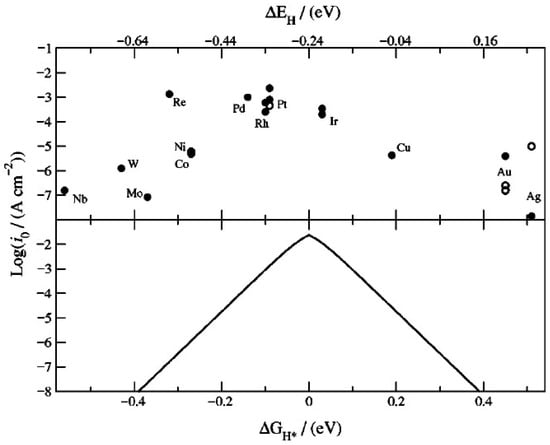
Figure 6.
Semi-logarithmic plot of experimentally determined exchange current density versus the calculated chemisorption energy per hydrogen atom DEH (upper) and theoretical kinetic model of exchange current density versus free energy change for hydrogen adsorption DGH* (lower). Used with permission of The Electrochemical Society, from ‘Trends in the exchange current for hydrogen evolution’, J.K. Noskov, T. Bligaard, A. Logadottir, J.R. Kitchin, H.G. Chen, S. Pandelov and U. Stimming, Journal of the Electrochemical Society, 152 (3), J23–26 (2005) [64]; permission conveyed through Copyright Clearance Center Inc.
Amongst the multi-metallic amorphous TMS, the most promising electrocatalyst for HER is the bifunctional NiFeSx/NiFe(OH)y. The η10 and Tafel slope of this composite are comparable to a-NiSx but j0 is higher, suggesting higher intrinsic activity at catalytic sites. The low value of the h100 shows that this composite bifunctional electrocatalyst has potential for industrial applications. An electrolyzer based on NiFeSx/NiFe(OH)y || NiFeSx/NiFe(OH)y electrodes in 1 M KOH has a low onset voltage of 1.39 V at 10 mA/cm2 at 40 °C [59].
Further insight can be gained by comparing the amorphous TMS electrocatalyst parameters in Table 1 and Table 2 with those of mono-metallic and multi-metallic crystalline TMS (c-TMS) electrocatalysts in Table 3. The materials data in Table 3 are taken from the recent literature [65,66,67,68]. The a-NiSx deposited by the CBD method has lower h10 and Tafel slope than crystalline NiS2 formed on NiV LDH and polycrystalline NiS2 film on polished glassy carbon (GC) [65]. However, for a-NiSx prepared by the electrodeposition and sol-ge/precursor routes, the h10 is higher than crystalline NiS2 [66]. This shows that the electrocatalytic performance of amorphous TMS is not necessarily better than crystalline TMS and is strongly dependent on the deposition method. Similar observations can be made when a-CoSx and a-FeSx are compared with their crystalline counterparts [67,68].
Table 3.
Electrocatalytic properties of selected mono- and multi-metallic first-row c-TMS.
A comparison should also be made with the more widely studied amorphous second-row TMS electrocatalyst a-MoSx and the benchmark Pt/C. For the former, according to the initial 2011 publication [69], amorphous MoS3 deposited by cyclic voltammetry on rotating glassy carbon in 1 M H2SO4 has a η = 200 mV at the current density 14 mA/cm2. This is comparable to the η10 of electrodeposited a-NiSx on FTO and higher than CBD a-NiSx/NF (Table 1). As for Pt/C, the η10 and Tafel slope has been reported as 44 mV and 38 mV/dec, respectively, in 1 M KOH [42]. These are about 83% of the η10 and 56% of the Tafel slope for a-NiSx prepared by the CBD method, demonstrating that promising progress has been made.
5. Amorphous Third-Row TMS HER Electrocatalysts
For the third row of the transition metal series (atomic number 71–80) in the Periodic Table, only tungsten (W) thus far is known to form amorphous sulfides with electrocatalytic properties for the HER. In 2015, Xiao et al. used ECD to deposit amorphous tungsten sulfide (a-WSx) onto nanoporous gold (NPG) to form a composite a-WSx/NPG electrode and demonstrated good catalytic performance [49]. The NPG with larger effective surface area than a conventional electrode was prepared by selective wet etching of silver (Ag) from an Au/Ag leaf alloy. After this dealloying, the NPG film was transferred to a polished glassy carbon electrode and a-WSx was electrodeposited using an electrochemical cell containing an aqueous electrolyte with 0.1 M KCl and 5 mM of ammonium tetrathiotungstate ((NH4)2WS4). The non-crystalline nature of the deposited film was confirmed by XRD, and the presence of W and S was determined by energy dispersive X-ray spectroscopy. When tested for HER activity by LSV in 0.5 M H2SO4, the optimized a-WSx/NPG bilayer electrode showed an onset overpotential of 108 mV and a η10 of ~150 mV. The extracted Tafel slope b and j0 are 74 mV/dec and 1.2 mA/cm2, respectively. It is significant that the Tafel slope for a-WSx/NPG is much lower than that for a-WSx (127 mV/dec) and glassy carbon (135 mV/dec). This study highlighted the fact that the porosity of the support layer is crucial to the performance of a-WSx electrocatalysts. The stability of a-WSx/NPG in acidic electrolyte was studied by LSV cycling. No change in the polarization curve was observed after 500 cycles.
a-WSx has also been prepared by Yang et al. using a simple thermolysis technique [50]. This technique was previously used for the deposition of crystalline WS2 [70]. The thermolysis process involves first dissolving (NH4)2WS4 in hydrochloric acid to form a stock solution. Droplets of this aqueous solution were deposited onto either FTO or glassy carbon substrates. The wetted substrate was transferred into the quartz tube of a chemical vapor deposition (CVD) furnace and thermal annealing was performed at 210 °C for 30 min in flowing nitrogen gas. During this annealing period, (NH4)2WS4 decomposes into a-WSx. For the preparation of a-WSx, it is crucial to choose an annealing temperature between 150 and 310 °C because at higher temperatures, crystalline 2H-WS2 polytype will form instead [53].
Although mono-metallic a-WSx can be easily prepared by thermolysis, it is not suitable for HER electrocatalysis. This is because, as shown by SEM, the as-synthesized a-WSx has a branched texture with a characteristic length scale of micrometers. Furthermore, when tested in a 3-electrode cell with a Pt mesh counter electrode and an Ag/AgCl reference electrode, the polarization curve for a-WSx in 0.5 M H2SO4 solution showed an onset potential of approximately 300 mV vs. RHE, and the η10 is 604 mV vs. RHE (Table 1) [50]. These overpotentials, which are significantly higher than the corresponding values for amorphous first-row TMS HER electrocatalysts, can be explained by the higher chemisorption energy of hydrogen on W, as shown by the volcano curve (Figure 6).
The electrocatalytic properties of a-WSx can be significantly enhanced by incorporating optimized concentrations of Co2+ or Ni2+ ions into a-WSx. When cobalt (II) chloride hexahydrate (CoCl2·6H2O) is added to an aqueous solution of (NH4)2WS4 at a Co:W atomic ratio of 1:3, the a-CoWSx film obtained by thermolysis at 210 °C has a lower overpotential at 10 mA/cm2 of 330 mV (Table 2). This overpotential can be further reduced to 250 mV by using cobalt (II) acetate as a cobalt source in a-CoWSx [50]. In the Tafel analysis of ohmic loss corrected current density–voltage data, Yang et al. showed that a-CoWSx has an exchange current density j0 of 3.2 mA/cm2 and a Tafel slope b of 74 mV/dec. By contrast, a-WSx has a j0 value of only 0.86 mA/cm2 and b is 129 mV/dec. This shows that a-CoWSx has greater intrinsic catalytic activity and the HER kinetics are faster because of Co2+ on the reaction mechanism.
When Ni2+ is similarly incorporated into a-WSx using nickel (II) chloride hexahydrate (NiCl2·6H2O) at an optimized Ni:W atomic concentration of 1:3, the a-NiWSx film obtained by thermolysis at 210 °C showed a lower overpotential of 265 mV at 10 mA/cm2. This can be further reduced to the minimum value of 189 mV at 10 mA/cm2 when nickel (II) acetate is used instead as the Ni2+ source [50] (note that this overpotential of 189 mV is ~31% of the corresponding overpotential of a-WSx). In the Tafel analysis, Yang et al. reported an extracted j0 value of 3.5 mA/cm2 and a Tafel slope of 55 mV/dec for a-NiWSx (Table 2). These parameters showed that a-NiWSx has both higher intrinsic catalytic activity and faster HER kinetics because of the presence of Ni2+ ions. This is consistent with TOF measurements for a-NiWSx and a-CoWSx. For a-NiWSx and a-CoWSx, the measured TOF at 300 mV overpotential are 0.34 and 0.12 s−1, respectively. A durability test carried out by CA at 250 mV overpotential showed that the a-NiWSx can maintain a constant current density for 24 hrs. Hence, a-NiWSx is overall a more suitable HER electrocatalyst than a-CoWSx. One further notable difference between a-WSx and Ni- and Co-doped a-WSx is that the doped films have a uniform nanoporous morphology which results in a large effective surface area.
Figure 7 shows a bar chart comparison of the published η10 values for the W-based and first-row-based a-TMS HER catalysts listed in Table 1 and Table 2. It can be seen that the W-based catalysts have a generally higher h10 than the catalysts based on first-row metals. This can be understood from Figure 6, which shows that W has a higher chemisorption energy and free energy change in adsorption for hydrogen than Ni and Co.
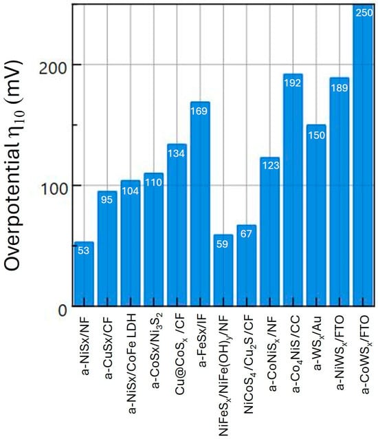
Figure 7.
Comparison of η10 of first- and third-row a-TMS HER electrocatalysts.
6. Conclusions and Outlook
Significant progress has been made in recent years in the development of amorphous HER electrocatalysts from sulfides of first- and third-row transition metals. For high electrocatalytic activity and durability in EWS systems, it is essential to incorporate Ni as one of the constituent elements of the electrocatalyst. This is due to the lower free energy change for hydrogen adsorption on Ni sites. In addition, both the deposition/synthesis method and the morphology of the support electrode can significantly influence the electrochemical properties of an a-TMS electrocatalyst. At present, the two most promising a-TMS HER catalysts are the bifunctional CBD a-NiSx and electrodeposited NiFeSx/NiFe(OH)y nanocomposite. An emerging strategy in HER electrocatalyst design is the fabrication of an amorphous–crystalline heterostructure within a three-dimensional nanostructured catalyst. This combines the advantages of the amorphous and crystalline components of the composite and results in high electrocatalytic activity. Examples include a-NiSx/CoFe LDH and CoWO4/NixFeyS. The search for a-TMS HER electrocatalysts with higher performance in future may include materials with multiple transition metal cations. In addition, fundamental surface science studies will be needed to identify the catalytic sites on a-TMS surfaces and what determines their concentration and the TOF. Advances in both structural characterization and computational modeling of amorphous materials will be required [71].
Funding
This research received no external funding.
Data Availability Statement
The raw data supporting the conclusions for this article will be made available by the author upon request.
Conflicts of Interest
Author declares no conflict of interest with respect to any organization.
References
- Abbasi, T.; Abbasi, S.A. ‘Renewable’ hydrogen: Prospects and challenges. Renew. Sustain. Energy Rev. 2011, 15, 3034–3040. [Google Scholar] [CrossRef]
- Bockris, J.O.M. The origin of ideas on a hydrogen economy and its solution to the decay of the environment. Int. J. Hydrogen Energy 2002, 27, 731–740. [Google Scholar] [CrossRef]
- Jones, K.; Ginley, D. Materials for electrification of everything: Moving towards sustainability. MRS Bull. 2021, 44, 1130–1138. [Google Scholar] [CrossRef]
- Kecebas, A.; Kayfeci, M. Hydrogen properties. In Solar Hydrogen Production: Process, Systems and Technologies; Calise, F., D’Accadia, M.S., Santarelli, M., Lanzini, A., Ferrero, D., Eds.; Elsevier Academic Press: London, UK, 2019; pp. 3–29. [Google Scholar]
- Schiffer, Z.J.; Manthiram, K. Electrification and decarbonization of the chemical industry. Joule 2017, 1, 10–14. [Google Scholar] [CrossRef]
- Borup, R.; Krause, T.; Brouwer, J. Hydrogen is essential for industry and transportation decarbonization. ECS Interface 2021, 30, 79–83. [Google Scholar] [CrossRef]
- Holladay, J.D.; Hu, J.; King, D.L.; Wang, Y. An overview of hydrogen production technologies. Catal. Today 2009, 139, 244–260. [Google Scholar] [CrossRef]
- Eryazici, I.; Ramesh, N.; Villa, C. Electrification of the chemical industry—Materials innovations for a lower carbon future. MRS Bull. 2021, 46, 1197–1204. [Google Scholar] [CrossRef]
- Kecebas, A.; Kayfeci, M.; Bayat, M. Electrochemical hydrogen production. In Solar Hydrogen Production; Elsevier: Amsterdam, The Netherlands, 2019; Chapter 9; pp. 299–317. [Google Scholar]
- Dincer, I. Green methods of hydrogen production. Int. J. Hydrogen Energy 2012, 37, 1954–1971. [Google Scholar] [CrossRef]
- Kusoglu, A. The many colors of hydrogen. ECS Interface 2021, 30, 44–48. [Google Scholar]
- Smolinka, T.; Bergmann, H.; Garche, J.; Kusnezoff, M. The history of water electrolysis from its beginnings to the present. In Electrochemical Power Sources: Fundamentals, Systems and Applications: Hydrogen Production by Water Electrolysis; Smolinka, T., Garche, J., Eds.; Elsevier: Amsterdam, The Netherlands, 2022; pp. 83–163. [Google Scholar]
- REN21. Renewables 2023 Global Status Report Energy Supply; REN21: Paris, France, 2023; p. 50. [Google Scholar]
- Bhattaharyya, R.; Mistra, A.; Sandeep, K.C. Photovoltaic solar energy conversion for hydrogen production by alkaline water electrolysis: Conceptual design and analysis. Energy Convers. Manag. 2017, 133, 1–13. [Google Scholar] [CrossRef]
- Service, R.F. The parting of water. Science 2025, 387, 354–357. [Google Scholar] [CrossRef]
- Carmo, M.; Fritz, D.L.; Mergel, J.; Stolten, D. A comprehensive review on PEM water electrolysis. Int. J. Hydrogen Energy 2013, 38, 4901–4934. [Google Scholar] [CrossRef]
- Janani, G.; Choi, H.; Surendran, S.; Sim, U. Recent advances in rational design of efficient electrocatalyst for full water splitting across all pH conditions. MRS Bull. 2020, 45, 539–547. [Google Scholar] [CrossRef]
- Zou, X.; Zhang, Y. Noble metal-free hydrogen evolution catalysts for water splitting. Chem. Soc. Rev. 2015, 44, 5148–5180. [Google Scholar] [CrossRef]
- Gupta, U.; Rao, C.N.R. Hydrogen generation by water splitting using MoS2 and other transition metal dichalcogenides. Nano Energy 2017, 41, 49–65. [Google Scholar] [CrossRef]
- Gou, W.; Zhang, M.; Wu, J.; Dong, Q.; Qu, Y. Pyrite-type electrocatalyst for hydrogen evolution. MRS Bull. 2020, 45, 555–561. [Google Scholar] [CrossRef]
- Hallenbeck, P.C.; Benemann, J.R. Biological hydrogen production: Fundamentals and limiting processes. Int. J. Hydrogen Energy 2002, 27, 1185–1193. [Google Scholar] [CrossRef]
- Zhang, D.; Soo, J.Z.; Tan, H.H.; Jagadish, C.; Catchpole, K.; Karuturi, S.K. Earth-abundant amorphous electrocatalysts for electrochemical hydrogen production: A review. Adv. Energy Sustain. Rev. 2021, 2, 2000071. [Google Scholar] [CrossRef]
- Mathi, S.; Akhdar, H.; Shetti, R.S.; Alinad, T.; Alodhayb, A.N.; Mondal, K.; Shetti, N.P. Amorphous electrocatalysts for oxygen and hydrogen evolution reactions: Advances in hydrogen production. Mater. Today Sustain. 2025, 32, 101223. [Google Scholar] [CrossRef]
- Morales-Guio, C.; Hu, X. Amorphous molybdenum sulfides as hydrogen evolution catalysts. Acc. Chem. Res. 2014, 47, 2671–2681. [Google Scholar] [CrossRef]
- Benk, J.D.; Xhen, Z.; Juritky, L.Y.; Forman, A.J.; Jaramillo, T.F. Amorphous molybdenum sulfide catalysts for electrochemical hydrogen production: Insights into the origin of their catalytic activity. ACS Catal. 2012, 2, 1916–1923. [Google Scholar] [CrossRef]
- Benk, J.D.; Hellstern, T.R.; Kibsgaard, J.; Chakthranont, P.; Jaramillo, T.F. Catalysing the hydrogen evolution reaction (HER) with molybdenum sulfide nanomaterials. ACS Catal. 2014, 4, 3957–3971. [Google Scholar] [CrossRef]
- Xia, Y.; Wu, W.; Wang, H.; Rao, S.; Zhang, F.; Zou, G. Amorphous RuS2 electrocatalyst with optimized active sites for hydrogen evolution. Nanotechnology 2020, 31, 145401. [Google Scholar] [CrossRef]
- Ursua, A.; Gandia, L.M.; Sanchis, P. Hydrogen production from water electrolysis: Current status and future trends. Proc. IEEE 2012, 100, 410–426. [Google Scholar] [CrossRef]
- Kurapati, N.; Buoro, R.M.; Amemiya, S. Perspective—Beyond the century-long paradigm of hydrogen electrochemistry through the Laviron-Amatore paradox. J. Electrochem. Soc. 2020, 167, 146514. [Google Scholar] [CrossRef]
- Du, N.; Roy, C.; Peach, R.; Turnbull, M.; Thiele, S.; Bock, C. Anion-exchange membrane water electrolyzers. Chem. Rev. 2022, 122, 11830–11895. [Google Scholar] [CrossRef] [PubMed]
- Suen, N.-T.; Hung, S.F.; Quan, Q.; Zhang, N.; Xu, Y.-J.; Chen, H.M. Electrocatalysts for the oxygen evolution reaction: Recent development and future perspectives. Chem. Soc. Rev. 2017, 46, 357–365. [Google Scholar] [CrossRef] [PubMed]
- Guo, T.; Li, L.; Wang, Z. Recent development and future perspectives of amorphous transition metal-based electrocatalysts for oxygen evolution reaction. Adv. Energy Mater. 2022, 12, 2200827. [Google Scholar] [CrossRef]
- Hamann, C.H.; Hamnett, A.; Vielstich, W. Electrochemistry; Wiley-VCH: Weinheim, Germany, 2007; pp. 162–169. [Google Scholar]
- Conway, B.E.; Tilak, B.V. Interfacial processes involving electrocatalytic evolution and oxidation of H2, and the role of chemisorbed H. Electrochim. Acta 2002, 47, 3571–3594. [Google Scholar] [CrossRef]
- He, R.; Hua, J.; Zhang, A.; Wang, C.; Peng, J.; Chen, W.; Zeng, J. Molybdenum disulfide-black phosphorus hybrid nanosheets as a superior catalyst for electrochemical hydrogen evolution. Nano Lett. 2017, 17, 4311–4316. [Google Scholar] [CrossRef]
- Van der Heijden, O.; Park, S.; Vos, R.E.; Eggebeen, J.J.J.; Koper, M.T.M. Tafel slope plot as a tool to analyze electrocatalytic reactions. ACS Energy Lett. 2024, 9, 1871–1879. [Google Scholar] [CrossRef]
- Gao, G.; Wang, L.-W. A potential and pH inclusive microkinetic model for hydrogen reactions on Pt surface. Chem Catal. 2021, 1, 1331–1345. [Google Scholar] [CrossRef]
- Kolasinski, K.W. Surface Science: Foundations of Catalysis and Nanoscience; Wiley: Chichester, UK, 2019; pp. 115–183. [Google Scholar]
- Gileadi, E. Physical Electrochemistry; Wiley-VCH: Weinheim, Germany, 2011. [Google Scholar]
- Zhan, C.; Lian, C.; Zhang, Y.; Thompson, M.W.; Xie, Y.; Wu, J.; Kent, P.R.C.; Cummings, P.T.; Jiang, D.; Wesolowski, D.J. Computational insights into materials and interfaces for capacitive energy storage. Adv. Sci. 2017, 4, 1700059. [Google Scholar] [CrossRef]
- Lian, C.; Jiang, D.E.; Liu, H.L.; Wu, Z. A generic model for electric double layers in porous electrodes. J. Phys. Chem. C 2016, 120, 8704. [Google Scholar] [CrossRef]
- He, W.; Wang, F.; Gao, Y.; Hao, Q.; Liu, C. One-step synthesis of amorphous transition metal sulfides as bifunctional electrocatalysts for the hydrogen evolution reaction and oxygen evolution reaction. Sustain. Energy Fuels 2022, 6, 3852–3857. [Google Scholar] [CrossRef]
- Jiang, N.; Bogoev, L.; Popova, M.; Gul, S.; Yano, J.; Sun, Y. Electrodeposited nickel-sulfide films as competent hydrogen evolution catalysts in neutral water. J. Mater. Chem. A 2014, 2, 19407–19414. [Google Scholar] [CrossRef]
- Karakaya, C.; Solati, N.; Savact, U.; Keles, E.; Turan, S.; Celebi, S.; Kaya, S. Mesoporous thin-film NiS2 as an idealized pre-electrocatalyst for a hydrogen evolution reaction. ACS Catal. 2020, 10, 15114–15122. [Google Scholar] [CrossRef]
- Wang, Z.; Mou, X.; Li, D.; Song, C.; Wang, D. Hierarchical flower-like amorphous nickel sulfide/crystalline CoFe layered double hydroxide heterostructure for overall water splitting. Int. J. Hydrogen Energy 2022, 47, 38124–38133. [Google Scholar] [CrossRef]
- Sun, Y.; Liu, C.; Grauer, D.C.; Yano, J.; Long, J.R.; Yang, P.; Chang, C.J. Electrodeposited cobalt-sulfide catalyst for electrochemical and photoelectrochemical hydrogen generation from water. J. Am. Chem. Soc. 2013, 135, 17699–17702. [Google Scholar] [CrossRef] [PubMed]
- Liu, Y.; Liu, Q.; Si, R.; Li, G.-D.; Li, W.; Liu, D.-P.; Wang, D.; Sun, L.; Zhang, Y.; Zou, X. Coupling sub-nanometric copper clusters with quasi-amorphous cobalt sulfide yields efficient and robust electrocatalysts for water splitting reaction. Adv. Mater. 2017, 29, 1606200. [Google Scholar] [CrossRef]
- Li, T.; Jiang, K.; Li, Y.; Luo, H.; Wang, Z.; Liu, Y.-Q. Crystalline nickel sulfide integrated with amorphous cobalt sulfide as an efficient bifunctional electrocatalyst for water splitting. Int. J. Hydrogen Energy 2023, 48, 7337–7345. [Google Scholar] [CrossRef]
- Xiao, X.X.; Engelbrekt, C.; Li, Z.; Si, P. Hydrogen evolution at nanoporous gold/tungsten sulfide composite film and its optimization. Electrochim. Acta 2015, 173, 393–398. [Google Scholar] [CrossRef]
- Yang, L.; Wu, X.; Zhu, X.; He, C.; Meng, M.; Gan, Z.; Chu, P.K. Amorphous nickel/cobalt tungsten sulfide electrocatalysts for high-efficiency hydrogen evolution reaction. Appl. Surf. Sci. 2015, 341, 149–156. [Google Scholar] [CrossRef]
- Ma, Q.; Hu, C.; Liu, K.; Hung, S.-F.; Ou, D.; Chen, H.M.; Fu, G.; Zheng, N. Identifying the electrocatalytic sites of nickel disulfide in alkaline hydrogen evolution reaction. Nano Energy 2017, 40, 148–153. [Google Scholar] [CrossRef]
- Zhou, X.; Li, X.; Chen, D.; Zhao, D.; Huang, X. Ultrathin CoFe-layered double hydroxide nanosheets embedded in high conductance Cu3N nanowire arrays with a 3D core-shell architecture for ultrahigh capacitance supercapacitors. J. Mater. Chem. A 2018, 6, 24603–24613. [Google Scholar] [CrossRef]
- Maghool, S.; Asgharinezhad, A.A.; Larimi, A.; Ghotbi, C.; Khorasheh, F. Efficient electrocatalysts for OER: Amorphous cerium-doped cobalt sulfide with enhanced performance and durability. Surf. Interfaces 2024, 54, 1050108. [Google Scholar] [CrossRef]
- Kale, S.B.; Bhardwaj, A.; Lokhande, V.C.; Lee, D.-M.; Kang, S.-H.; Kim, J.-H.; Lokhande, C.D. Amorphous cobalt-manganese sulfide electrode for efficient water oxidation: Meeting the fundamental requirements of an electrocatalyst. Chem. Eng. J. 2021, 46, 126993. [Google Scholar] [CrossRef]
- Merki, D.; Vrubel, H.; Rovelli, L.; Fierro, S.; Hu, X. Fe, Co and Ni ions promote the catalytic activity of amorphous molybdenum sulfide films for hydrogen evolution. Chem. Sci. 2012, 3, 2515. [Google Scholar] [CrossRef]
- Kumaravel, S.; Kundu, S. Sulfide and selenide-based electrocatalysts for hydrogen evolution reaction (HER). In Sulfide and Selenide Based Materials for Emerging Applications Sustainable Energy Harvesting and Storage Technology; Dalapati, G.K., Wong, T.K.S., Kundu, S., Chakraborty, A.K., Zhuk, S., Eds.; Elsevier: Amsterdam, The Netherlands, 2022; pp. 427–462. [Google Scholar]
- Dong, Y.; Fang, Z.; Yang, W.; Tang, B.; Liu, Q. Integrated bifunctional electrodes based on amorphous Co-Ni-S nanoflake arrays with atomic dispersity of active sites for overall water splitting. ACS Appl. Mater. Interfaces 2022, 14, 10277–10287. [Google Scholar] [CrossRef] [PubMed]
- Lu, W.; Li, X.; Wei, F.; Cheng, K.; Li, W.; Zhou, Y.; Zheng, W.; Pan, L.; Zhang, G. In-situ transformed Ni, S-Codoped CoO from amorphous Co-Ni-Sulfide as an efficient electrocatalyst for hydrogen evolution in alkaline media. ACS Sustain. Chem. Eng. 2019, 7, 12501–12509. [Google Scholar] [CrossRef]
- Che, Q.; Li, Q.; Tan, Y.; Chen, X.; Xu, X.; Chen, Y. One-step controllable synthesis of amorphous (Ni-Fe)Sx/NiFe(OH)y hollow microtube/sphere films as superior bifunctional electrocatalysts for quasi-industrial water splitting at large current-density. Appl. Catal. B Environ. 2019, 246, 337–348. [Google Scholar] [CrossRef]
- He, J.C.; Duan, D.C.; Du, Y.C.; Ding, Z.Q.; Yan, S.S.; Chen, X.; Zhang, H.; Bi, X.X.; Wang, R.Y.; Ge, X.B. Three-dimensional amorphous N-doped cobalt-copper sulfide nanostructures for efficient full water splitting. Rare Met. 2025, 44, 3080–3093. [Google Scholar] [CrossRef]
- Qian, Q.; Chen, C.; Zheng, X.; Wang, Q.; Gao, F.; Zou, Z. Hierarchical CoWO4/NixFeyS microspheres bearing crystalline-amorphous interface as a multifunctional platform for outperformed water splitting and sensitive hydrazine sensing. J. Colloid Interface Sci. 2024, 664, 756–765. [Google Scholar] [CrossRef] [PubMed]
- Wu, J.; Zhang, C.; Liu, M.; Xiang, C.; Zou, Y.; Xu, F. A crystalline-amorphous Cu-CuS2/NiCoS composite electrocatalyst with a hydrangea-like structure for efficient hydrogen evolution reaction. J. Alloys Compd. 2025, 1031, 180953. [Google Scholar] [CrossRef]
- Kibler, L.A. Hydrogen electrocatalysis. ChemPhysChem 2006, 7, 985–991. [Google Scholar] [CrossRef]
- NØrskov, J.K.; Bligaard, T.; Logadottir, A.; Kitchin, J.R.; Chen, J.G.; Paudelov, S.; Stimming, U. Trends in exchange current for hydrogen evolution. J. Electrochem. Soc. 2005, 152, J23–J26. [Google Scholar] [CrossRef]
- Liu, H.; He, Q.; Jiang, H.; Lin, Y.; Zhang, Y.; Habib, M.; Chen, S.; Song, L. Electronic structure reconfiguration toward pyrite NiS2 via engineered heteroatom defect boosting overall water splitting. ACS Nano 2017, 11, 11574–11583. [Google Scholar] [CrossRef]
- Kong, D.; Cha, J.J.; Wang, H.; Lee, H.Y.; Cui, Y. First-row transition metal dichalcogenide catalysts for hydrogen evolution reaction. Energy Environ. Sci. 2013, 6, 3553–3558. [Google Scholar] [CrossRef]
- Chen, P.; Zhou, G.T.; Chen, M.; Tong, Y.; Zhang, N.; Peng, X.; Chu, W.; Wu, X.; Wu, C.; Xie, Y. Enhanced catalytic activity in nitrogen-anion modified metallic cobalt disulfide porous nanowire arrays for hydrogen evolution. ACS Catal. 2017, 7, 7405–7411. [Google Scholar] [CrossRef]
- Chen, Y.; Xu, S.; Li, Y.; Jacob, R.J.; Kang, Y.; Liu, B.; Wang, Y.; Pastel, G.; Salamanca-Riba, L.G.; Zachariah, M.R.; et al. FeS2 nanoparticles embedded in reduced graphene oxide toward robust, high-performance electrocatalytsts. Adv. Energy Mater. 2017, 7, 1700482. [Google Scholar] [CrossRef]
- Merki, D.; Fierro, S.; Vrubel, H.; Hu, X. Amorphous molybdenum sulfide films as catalysts for electrochemical hydrogen production in water. Chem. Sci. 2011, 2, 1262–1267. [Google Scholar] [CrossRef]
- Chen, T.-Y.; Chang, Y.-H.; Hsu, C.-L.; Wei, K.-H.; Chiang, C.-Y.; Li, L.-J. Comparative study on MoS2 and WS2 for electrocatalytic water splitting. Int. J. Hydrogen Energy 2013, 38, 12302–12309. [Google Scholar] [CrossRef]
- Zhou, Y.; Fan, Y.J. Progress and challenge of amorphous catalysts for electrochemical water splitting. ACS Mater. Lett. 2021, 3, 136–147. [Google Scholar] [CrossRef]
Disclaimer/Publisher’s Note: The statements, opinions and data contained in all publications are solely those of the individual author(s) and contributor(s) and not of MDPI and/or the editor(s). MDPI and/or the editor(s) disclaim responsibility for any injury to people or property resulting from any ideas, methods, instructions or products referred to in the content. |
© 2025 by the author. Licensee MDPI, Basel, Switzerland. This article is an open access article distributed under the terms and conditions of the Creative Commons Attribution (CC BY) license (https://creativecommons.org/licenses/by/4.0/).