Abstract
As distributed energy resources (DERs) become increasingly integrated into distribution systems, ensuring safe and reliable interconnection has become a critical challenge. This study explores the use of an Advanced Distribution Management System (ADMS) as a technical review tool for DERs interconnection. The proposed approach enables users to reflect newly requested DERs into the operational analysis database and evaluate their impact using ADMS study mode. Key ADMS functionalities, including network modeling, load estimation, voltage analysis, and protection coordination checks, are described and applied to DERs interconnection scenarios. The study demonstrates that ADMS not only improves the reliability of technical assessments but also allows for automated evaluation of all criteria defined in the DERs interconnection technical guidelines—including thermal capacity, voltage impact, and protection coordination. This study demonstrates that stable operation of the distribution system can be achieved even with the increasing penetration of DERs, while also contributing to reduced reviewer workload and improved transparency and traceability.
1. Introduction
The deployment of distributed energy resources (DER), particularly those based on renewable energy, is increasing globally. South Korea’s Renewable Energy 3020 initiative has accelerated the deployment of DERs at the distribution level. In South Korea, the number of DERs connected to the distribution system is also rising, driven by government policies []. As DERs penetration deepens, KEPCO—the operator of the Korean distribution network—faces the challenge of integrating these resources while maintaining a stable and reliable power supply. In response, KEPCO has developed an Advanced Distribution Management System (ADMS) to enhance the visibility and operational efficiency of the distribution network. This transition has enabled KEPCO to evolve from a traditional Distribution Network Operator (DNO), which relied primarily on switchgear operations for limited flexibility, into a Distribution System Operator (DSO) capable of achieving wide-area flexibility through integrated system control [,]. This transition provides valuable insights for other countries with centralized utility structures and increasing DERs penetration, especially those preparing to adopt ADMS platforms.
KEPCO evaluates factors such as voltage levels, thermal capacity, and protection coordination to determine whether a DERs can be connected to the distribution network. This process is known as the DERs technology review. Before the implementation of the ADMS, KEPCO operated a Distribution Automation System (DAS), under which the DERs technology review was conducted based on worst-case scenario assumptions due to limited system visibility. As a result, the reliability of the review outcomes was low, as they were based on inaccurate data and numerous assumptions [,,,,]. However, with the introduction of ADMS, KEPCO has significantly improved system visibility, resulting in greater accuracy and reliability in the DERs technology review process.
Numerous efforts have been made to assess hosting capacity (HC) and evaluate DERs interconnection in distribution networks. These include analyses considering voltage unbalance [], simplified methods for estimating PV-based HC [], enhancement through an active or reactive power control [], the effect of conservation voltage reduction [], and the development of DOE’s HCA tool []. However, most of these studies primarily focus on simulation-based HC estimation and lack integration with real operational platforms. They do not offer comprehensive procedures for evaluating multiple technical criteria such as protection coordination and thermal capacity in actual DERs interconnection scenarios. Several studies have also focused on validating ADMS or distributed energy resources management system (DERMS) control functions. These include interoperability testing between microgrids and ADMS [], DERMS strategies for enhancing grid operations [], advanced hierarchical control structures [], and comparative evaluations of Volt-VAR and secondary VAR controllers’ methods [,]. While valuable for system stability and resilience, these works do not offer structured workflows for DERs interconnection assessments, nor do they connect operational evaluations with planning/design systems. Integration between control and review functions remains limited. Significant contributions have also come from studies addressing cybersecurity, communication structures, and data management. These include cyber-physical threat analysis in DERs integration [], DERMS coordination across TSO-DSO boundaries [], data hub-based DERs integration platforms [], estimation of behind-the-meter DERs using smart meters [], and co-simulation approaches for cybersecurity analysis []. These studies focus more on architecture and data handling strategies than on operationalizing technical reviews within utility workflows. They fall short in delivering automation-ready assessments grounded in real grid models. In addition, active research has also explored distribution system planning and strategic frameworks. These include optimization-based planning for DERs integration [] and the future role of power electronics in grid evolution as discussed in major workshops []. While these works provide planning insights, they lack the specificity required to be directly applied to DERs interconnection review processes.
Unlike previous studies that mainly focused on DERMS- or HCA-based simulations, this study presents a fully operational ADMS platform that directly supports technical review and decision-making for DERs interconnection within a national utility. The proposed framework differs from conventional approaches in three key aspects. First, it enables real-time integration between operational (FA) and planning (OA) environments, minimizing data latency and manual updates. Second, it provides automated, criteria-based assessments covering voltage, thermal, and protection analyses within a single workflow. Third, it establishes a transparent and traceable process that links review results to subsequent design and construction stages. This combination of automation, interoperability, and practical deployment makes the study one of the first utility-scale implementations of ADMS for DERs interconnection assessment. Building on KEPCO’s transition to an ADMS-based system, the paper outlines the current DERs review guidelines, key ADMS functions supporting the review process, and the developed tool that enhances the precision and consistency of DERs feasibility assessments.
Section 2 outlines the DERs technology review guidelines. Section 3 presents selected functions of the ADMS that support the DERs technology review process. Section 4 introduces the ADMS-based review tool developed by KEPCO. Finally, Section 5 summarizes the key contributions of this study and discusses its potential applications. Specifically, this study contributes by developing a tool that utilizes application based on power flow to improve the precision of DERs feasibility assessments.
2. Procedures for Distributed Energy Resources Integration in South Korea
Section 2 outlines the complete process for integrating DERs in South Korea, covering both the administrative procedures and the technical review required from the initial connection request by the DERs operator to the start of commercial operation. Section 2.1 describes the regulatory and administrative steps involved, while Section 2.2 focuses on the technical criteria and review procedures implemented by KEPCO (Naju, Republic of Korea).
2.1. Administrative Procedures for Integrating Distributed Energy Resources
Figure 1 illustrates the administrative procedures for DERs integration between DERs operators and the DSO. When a DERs operator submits an interconnection request, the DSO conducts a technical assessment, including protection coordination and power quality analysis. If necessary, the DSO reinforces the system by reconfiguring the distribution network or installing additional facilities such as substations, main transformers, or step voltage regulators (SVR). Once the technical issues are resolved, the DSO issues a cost estimate or bill to the DERs operator. Upon payment, the DSO proceeds with the construction work, including the required system reinforcements. After the interconnection is completed, an operating contract is signed, and the DERs begins commercial operation. These administrative steps serve as a prerequisite to the technical review process, ensuring that DERs interconnection requests follow a standardized and transparent procedure [].
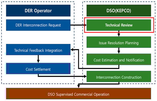
Figure 1.
Administrative procedures for integrating DERs with the distribution system in South Korea.
2.2. Technical Review for Distributed Energy Resources Integration
After addressing the administrative procedures, the next step is to conduct a comprehensive technical review of the DER’s impact to ensure stable and safe integration into the distribution network. The technical review process, summarized in Figure 2, is designed to verify that each interconnection request meets the operational and safety criteria defined in KEPCO’s technical guidelines.
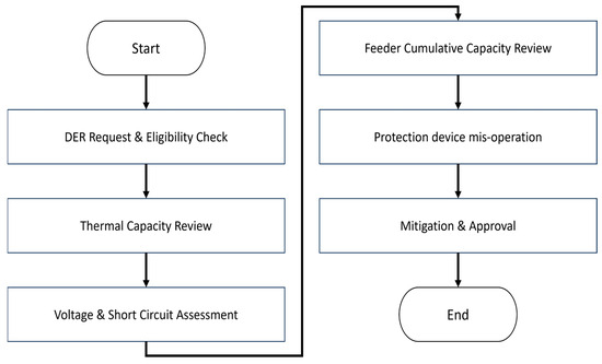
Figure 2.
Simplified technical review process for DERs interconnection.
In the first stage, the DSO confirms the basic eligibility of the DERs request by checking feeder and transformer capacity limits. If the proposed capacity exceeds the allowable thermal or operational range, the DERs must be connected through a dedicated feeder.
The second stage focuses on voltage performance and short-circuit capacity. This step evaluates whether the DERs connection may cause excessive voltage fluctuation or transformer tap operations and ensures that the resulting fault current remains within the rated capacity of circuit breakers and protective devices. The instantaneous voltage variation caused by a change in DERs output can be expressed as follows:
where
: Instantaneous voltage variation at the DERs connection point [%],
%R: Resistance component of the feeder impedance expressed as a percentage [%],
%X: Reactance component of the feeder impedance expressed as a percentage [%],
: Power factor angle of the DERs output [rad], and
: Rated apparent power of the DERs [kVA].
The acceptable limits of instantaneous voltage variation are less than 3% for wind power, 4% for solar power, and 5% for small hydro power.
The third stage assesses the cumulative impact of all DERs connected to the same feeder. When the total DERs capacity approaches the feeder’s permissible threshold, potential over-voltage and protection-device non-operation are examined. If violations are identified, the DSO considers corrective measures such as network reconfiguration, installation of step-voltage regulators (SVR), or conductor reinforcement.
In the final stage, the potential for protection-device mis-operation caused by bi-directional fault currents is reviewed. Countermeasures—including the installation of neutral-grounding reactors or advanced relays with bi-directional detection capabilities—are recommended where necessary. Through this structured process, the DSO systematically evaluates capacity, voltage, and protection coordination to ensure that DERs interconnection satisfies all technical requirements and maintains overall system reliability.
In addition to voltage and capacity evaluations, the review also includes an assessment of protection-device performance under fault conditions. Figure 3 illustrates a case in which the reduction of fault current due to DERs impedance causes non-operation of a circuit breaker, whereas Figure 4 shows a mis-operation caused by reverse fault current flowing through a DERs transformer. These examples represent typical scenarios considered in the protection-coordination step of the review process and emphasize the importance of ensuring accurate detection of bi-directional fault currents in DER-integrated systems.
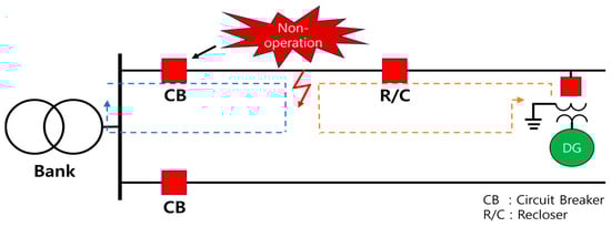
Figure 3.
Example of protection device non-operation during a single-line ground fault scenario.
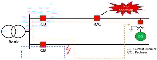
Figure 4.
Example of protection device mis-operation during a single-line ground fault scenario.
Once the technical issues have been addressed, the DSO issues a bill to the DERs operator. After payment is received, the DSO proceeds with the construction work, including any necessary reinforcements to the distribution system. The overall technical review process ensures that DERs interconnection does not compromise the reliability or safety of the distribution network. Through systematic evaluation of capacity, voltage, and protection coordination, the DSO can maintain grid stability while facilitating the integration of renewable energy resources.
3. ADMS Functions for DERs Integration Technology Review
The existing distribution operation system, the Distribution Automation System (DAS), was primarily used to reconfigure the distribution system during construction or to isolate fault sections by operating switches. To respond to the rapid increase in the DERs penetration, KEPCO enhanced the visibility and flexibility of the distribution system by transitioning from DAS to the ADMS. KEPCO currently operates a distribution network composed of approximately 12,000 distribution lines and around 165,000 automatic switches. This section introduces only the functions of KEPCO’s ADMS that are relevant to the DERs interconnection technology review. To overcome the limitations of the previous DERs review process, ADMS provides core functions as discussed in the following section.
3.1. ADMS Information Flow for DERs Integration
The power grid, one of the nation’s core infrastructures, is segmented for security purposes. KEPCO maintains two separate networks: the FA network, which directly controls power facilities, and the OA network, which supports administrative operations. Figure 5 shows the information flow of ADMS. When transitioning from DAS to ADMS, the DAS database is migrated, and the DER-related data is added to build the ADMS database. After the ADMS database is constructed, application software performs calculations using real-time values measured from terminal devices. The ADMS, installed on the FA network, operates 24 h a day in the operation center. Application software runs according to a schedule. Therefore, key applications such as power flow calculation, load estimation are run on a scheduled basis, thereby enhancing distribution system visibility. The distribution system database, section load data, and operating history produced in the FA network are imported into the OA network for use in study mode. In this mode, operation plans are developed by simulating the system by deriving the setting values of protection devices and voltage control equipment and analyzing the voltage and fault current of the simulated system. The DERs interconnection technical review, which is the focus of this paper, is conducted within this study mode.
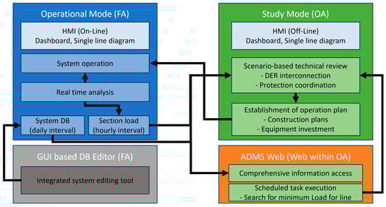
Figure 5.
The ADMS DB information flow between FA and OA network.
In practical operation, the FA network updates real-time data every hour, which are securely transferred to the OA network through a firewall-protected communication channel. To ensure data integrity, checksum validation and time-stamp verification are applied during each synchronization cycle. This design prevents mismatches between real-time measurements and the analytical database, ensuring that the ADMS study mode reflects the latest system conditions. The secure FA–OA interface also complies with cybersecurity standards for critical infrastructure, preventing unauthorized data access while maintaining operational reliability.
3.2. Distribution System Modeling
Distribution lines in South Korea are typically operated at 22.9 kV and follow a radial configuration consisting of components such as circuit breakers and protection devices. The ADMS manages the 22.9 kV distribution system and analyzes the higher-level transmission system using equivalent impedance models or SCADA data. The secondary side of the distribution transformer (22.9 kV/380, 230 V) is monitored using Advanced Metering Infrastructure (AMI), which enables real-time measurement and status assessment of the low-voltage network. Figure 6 demonstrates the concept of modeling an actual distribution system within the ADMS environment, representing its structural configuration and relevant components. Due to the complexity of the distribution system, it is represented in a simplified format using a single-line diagram, which highlights the essential components and their interconnections without depicting the full physical layout. Representative equipment in the distribution network includes circuit breakers, switches, conductors, high-voltage customers, and DER, each playing a critical role in maintaining system stability and operational reliability. Many poles, particularly those with distribution transformers, are abstracted and modeled as nodes representing system connection points. The large-capacity DERs (500 kW or more) are directly connected to the 22.9 kV distribution network, with DERs operators installing dedicated interconnection transformers. In contrast, the small-capacity DERs are integrated through distribution transformers installed and managed by KEPCO to ensure safe and consistent operation. DERs models are managed by grouping them into distribution transformer units, allowing for efficient tracking and modeling. Each DERs customer is identified by a unique contract number. For instance, as shown in Figure 6, even when multiple DERs are connected to a single transformer, they are modeled as multiple customers under a single generator. The characteristics of the interconnection transformer are managed in the database, while the individual DERs attributes are stored for customers.
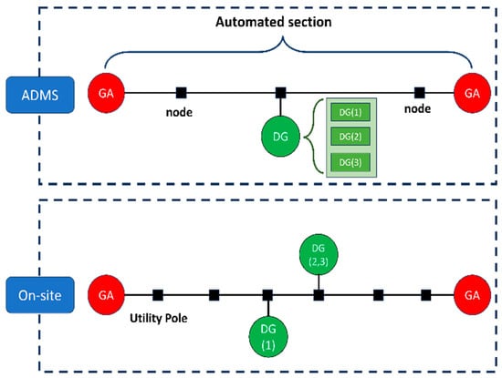
Figure 6.
Example of modeling a real distribution system in ADMS.
3.3. Section Load Definition and Estimation Methods
In the legacy DAS, system operation relied heavily on operator experience and the current measured at the switches. The voltage measurements from the switches were often unreliable, leading to operation based on inaccurate information. The operating plan used load history measured at the feeder outflow point within the substation. Since this data was managed on a per-feeder basis, voltage estimation was performed by evenly allocating the load across sections. This approach lacked accuracy due to significant differences between actual and estimated voltages. Furthermore, because the load data was collected only at the feeder outflow point, it was difficult to trace historical data according to the current distribution system topology. Even when the topology changed, the system continued storing data from the outflow point as feeder load history, without recognizing the structural changes. Consequently, DSO operators would create operational plans based on outdated or incorrect topological assumptions. To resolve this issue, ADMS includes application software for estimating section-level load.
Figure 7 shows the concept of an application developed to generate sectional load data, designed to address limitations of the legacy DAS. To manage sectional load effectively, it is essential to first establish a reference direction for power flow.
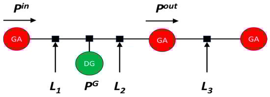
Figure 7.
Design of the sectional load generation application.
Let a section i be a network segment bounded by two automated devices. Denote upstream/downstream active power at the section boundaries by and , the DERs by , and the total load within the section by . Using the reference direction inferred for CT, the section power balance is as the following:
where
: Total load of section [kW],
: Active power flowing into section ifrom the upstream node [kW],
: Active power flowing out of section itoward the downstream node [kW],
: Total active power generated by DERs connected to section [kW],
S: The set of consecutive to which the section belongs (),
N: Total number of sections (network segments) in the feeder,
: Signed active power measurement corrected for CT reference direction [kW],
s: Reference direction sign for each CT (; +1 = forward, −1 = reversed),
V: Measured line-to-neutral voltage magnitude [V],
I: Measured current magnitude [A], and
: Power-factor angle between voltage and current [rad].
In traditional distribution systems, typically power flows from the source to the load. However, with the increasing penetration of DER, reverse power flow is becoming more common. While automated devices can detect reverse power flow, the reference direction of current transformers (CT) can change due to network reconfiguration—a common feature of distribution systems. Therefore, accurately determining the reference direction is crucial. In the ADMS, the reference direction of CT is inferred during time periods when reverse power flow does not occur, enabling accurate interpretation of current flow. The term section load refers to the net load, generation, and gross load within a segment defined between two automated devices (e.g., switches). Equation (5) defines the procedure used in ADMS to automatically infer the reference direction of each CT. because CT may be installed in either orientation and the distribution system topology can change frequently due to switching or reconfiguration, the measured active power () at device d can appear with an incorrect sign. To ensure consistency in power-flow calculations, the ADMS determines the correct CT polarity by analyzing operational data during nighttime hours when DERs is inactive, and all feeders operate under unidirectional power flow. During this period, reverse current is absent, allowing the system to infer the CT reference direction by selecting the orientation that results in the greatest number of positive power-flow measurements under the assumed direction. In other words, when , the power flow is consistent with the assumed CT orientation and regarded as forward. However, if during nighttime hours—when DER is zero and reverse flow should not exist—the system recognizes that the CT polarity is reversed and updates the reference sign accordingly. Once is determined, this sign is applied to all subsequent measurements to maintain consistent power-flow orientation throughout section-load estimation and voltage-analysis processes as follows:
where
: Inferred CT reference direction for device (+1 = forward, −1 = reversed),
: Measured active power at device and time [kW],
: Reference time window during which reverse flow is absent,
: Indicator function, equals one if the condition is true, zero otherwise, and
: Operator that returns the value of producing the largest summation value.
Figure 8 illustrates the simplified data flow used by the ADMS to estimate the output of DER. When real-time measurements are unavailable, the system calculates generation rates based on nearby monitored DERs and solar irradiance data collected through the AMI network. These calculated rates are then used to estimate the output of unmonitored DER, improving the accuracy of distribution-system operational analysis without requiring additional field instrumentation.
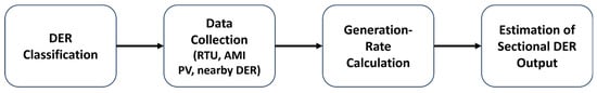
Figure 8.
The data flow for estimation DERs output using AMI and irradiance data.
In practical operation, not all DERs are equipped with real-time measurement devices. Therefore, the ADMS estimates the power output of unmonitored DERs by using data from nearby monitored DERs and irradiance information collected through the AMI. This estimation enables section-level load calculation and voltage analysis to accurately reflect the total DERs in the feeder. To derive the unmonitored DERs output, the ADMS first computes a capacity-normalized generation ratio based on monitored DER, then scales it by each unmonitored DER’s rated capacity and irradiance-based correction factor.
The procedure is formulated as follows:
where
Measured active power of monitored DER at time [kW],
: Estimated active power of unmonitored DER at time [kW],
: Rated capacity of DERs or [kW],
: Set of monitored DERs with real-time measurement,
: Set of unmonitored DERs without direct measurement,
: Subsets of monitored/unmonitored DERs connected to section i,
G(t): Solar irradiance or AMI-based representative variable at time t,
f(G): Normalized irradiance correction function,
a(t): Capacity-normalized generation ratio derived from monitored DERs, and
: Total DERs generation aggregated at section i [kw].
4. DERs Interconnection Technology Review Using ADMS
4.1. Editing DB for Technology Review
Before discussing the editing process, it is necessary to clarify why database editing is an essential step in the DERs technology review. The interconnection assessment of DERs requires accurate reflection of the DERs operator facility and network information within the distribution system model. To evaluate whether the new DERs can be technically connected—considering voltage, thermal, and protection constraints—the relevant database must be edited to incorporate the proposed interconnection point, DERs parameters, and operating conditions. Without proper editing, simulation and analysis results would not represent the actual system configuration, leading to unreliable assessment outcomes. In the legacy DAS environment, where editing within the study mode was limited and cumbersome, it was difficult to perform a reliable and consistent technical review of DERs interconnections. In contrast, the ADMS-based approach proposed in this study enables accurate and efficient database editing directly within the operational framework, thereby supporting a more transparent and trustworthy interconnection assessment process.
When a DERs operator requests interconnection to the distribution system, the DB is edited to prepare a case study for the technical review. The FA network database contains only currently operating DERs for real-time control. In contrast, the OA network database—used for technical review—also reflects only operating DERs unless it is manually edited to include new or pending DER.
For a reliable DERs technical review, it is necessary to consider DERs that are awaiting interconnection. Therefore, DERs under review for potential interconnection should be added to the OA network database through editing. DERs that are currently energized are referred to as operational DERs, while those awaiting interconnection or under review are classified as new DERs.
In ADMS study mode, there are two methods for editing the database of new DERs for interconnection technical review. The first method involves editing the database through a schematic diagram with a GUI; and the second method manages new DERs directly within the OA network database. Since the schematic diagram editing method is identical to that used in the FA network’s ADMS DB, no additional user training is required. This method is recommended when large-scale edits (e.g., feeder or substation modifications) are needed in addition to adding new DERs, as illustrated in Figure 9.
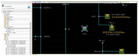
Figure 9.
Example of GUI-based schematic editing interface for adding new DERs in ADMS study mode.
The second method involves text-based DB editing, which reduces editing time and enhances user convenience. As shown in Figure 10, when users edit parameters such as capacity, location, and transformer type for a new DER, the changes are immediately reflected in the technical review database. This method allows users to quickly register multiple DERs using structured templates or CSV formats, significantly reducing manual input time, and lowering the chance of errors. In addition, this approach ensures that updates such as changes in system topology or the addition of equipment are automatically reflected in the database, thereby enhancing the reliability and accuracy of the technical review results.
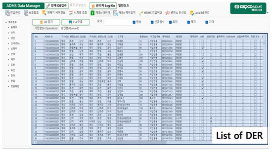
Figure 10.
Example of text-based database editing interface for new DERs registration.
4.2. Technical Review Results Using ADMS
Figure 11 shows the ADMS study mode screen, which is launched after editing the database as described in Section 4.1. When the reviewer selects the substation and feeder related to the DERs under review in part (1) Figure 11, a list of DERs is generated as shown in part (3) Figure 11. This list includes DERs that are currently operating on the FA network as well as newly added DERs edited in Section 4.1. Additionally, the list displays information such as customer name, contract number, connection location, generator type, and voltage control capability. This allows reviewers to have a comprehensive view of all DERs affecting the selected feeder.
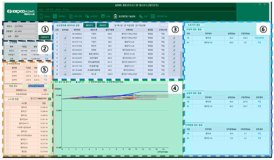
Figure 11.
Interface for DERs interconnection assessment using the ADMS study mode.
The reviewer selects the DERs to be reviewed based on the provided information and proceeds with the technical evaluation. The marked as (2) in Figure 11 shows the cumulative capacity of DERs aggregated by substation, bank, and feeder. Detailed voltage value and the instantaneous voltage variation rate are presented in part (5) of Figure 11, allowing for the evaluation of voltage performance at the DERs interconnection point. The part (4) of Figure 11 shows the voltage profile based on impedance, which is used to assess voltage violations step by step. The review is conducted based on the operating history at the time of the minimum net load of the year. This minimum load scenario represents the worst case for evaluating DERs interconnection feasibility. The output voltage is based on the bank’s secondary voltage at the time of minimum load. To evaluate the voltage performance of a new DERs interconnection, the ADMS performs a four-stage analysis based on the operational states of existing and new DERs. Let denote the bus voltage magnitude at node in stage , and be the nominal reference voltage (1.0 pu).
The voltage deviation at each node is defined as the following:
The four evaluation stages are summarized as follows:
In each stage , the ADMS computes the voltage profile through a load-flow calculation and flags any node that violates condition. The final voltage assessment is based on whether all nodes satisfy .
If violations persist even in Stage 4, additional system reinforcements such as installing SVRs, reconfiguring the distribution network, or changing line types are considered. This staged approach ensures fairness among DERs applicants and prevents unnecessary overinvestment by the DSO.
The part (6) of Figure 11 displays the results of protection device analysis, including potential mis-operation, non-operation, and short-circuit capacity violations. As explained in Figure 3 and Figure 4, mis-operation or non-operation may occur due to fault current contributions from DER-connected transformers. For mis-operation, the DSO can replace the device with one capable of bidirectional fault current detection. For non-operation, mitigation measures include installing a neutral grounding reactor in the interconnection transformer or changing the line type. Based on the evaluation results, the DSO determines whether additional equipment or configuration changes are necessary, and if so, associated costs are billed to the DER operator.
In summary, if no issues are identified in thermal capacity, voltage profile, or protection coordination, the DSO approves the interconnection of the DERs to the distribution network. Thermal capacity constraints can be addressed by changing conductor types, reconfiguring feeders, or constructing new transformers or lines. Voltage issues are primarily mitigated through DER-side control functions, such as Volt-Var control or power factor management. If further adjustments are required, the DSO considers system-level measures, including On Load Tap Changer (OLTC) control or the installation of SVR. Protection coordination problems are resolved by upgrading protective devices or installing appropriate components, such as neutral grounding reactors.
Importantly, unlike previous tools that only supported partial review—typically for voltage and protection coordination—while requiring manual assessment for the remaining items, the ADMS study mode enables comprehensive automated evaluation across all criteria specified in the DER interconnection technical review guidelines. In addition, the tool automatically generates a technical review report, which can be uploaded directly into the design system. This not only facilitates seamless integration with subsequent design processes but also helps standardize the review process, thereby enhancing transparency and reliability. Furthermore, the automation and streamlined workflow significantly reduce the workload for reviewers, supporting more efficient and consistent decision-making across DER interconnection projects.
5. Conclusions
This study examined the procedures and challenges involved in the interconnection of DERs within distribution systems, with particular emphasis on the role of an ADMS in enhancing the technical review process. The findings demonstrate that an ADMS-based technical review tool significantly improves the reliability, transparency, and efficiency of DERs interconnection assessments compared with conventional methods.
Section 1 identified the growing need for systematic DERs interconnection procedures as distributed generation continues to expand. Section 2 introduced the current administrative and technical procedures of DERs integration in South Korea, including a review of relevant regulations, stakeholders, and interconnection workflows. Section 3 explored the key ADMS functions that support DERs integration, such as FA–OA information flow, network modeling, and section-load estimation. Section 4 demonstrated how ADMS is practically used for technical reviews through a structured four-stage process that evaluates capacity, voltage, and protection coordination.
By leveraging the ADMS study mode within the OA network, utilities can conduct more accurate and consistent reviews that reflect real-time network conditions. The standardized and automated workflow reduces human error, enhances traceability, and facilitates seamless linkage with subsequent design and construction processes. These capabilities enable utilities to maintain grid stability while accommodating the rapid growth of distributed generation.
Although Korea has already achieved nationwide deployment of ADMS, several technical and operational challenges remain for its continuous improvement. Maintaining data consistency and interoperability among legacy systems, such as SCADA, GIS, and DERs registration databases, is essential, particularly as the scale of DERs integration expands. Continuous validation and synchronization between the OA and FA networks are required to ensure reliable analytical results.
In addition, cybersecurity and access control must evolve alongside increasing data exchange between real-time operational and planning environments. The establishment of secure communication protocols and automated integrity checks is crucial to prevent vulnerabilities. Furthermore, organizational adaptation and operator training remain important to fully utilize the system’s analytical capabilities.
From a research perspective, future development should focus on incorporating AI-driven analytics, digital twins, and dynamic hosting capacity estimation within the ADMS environment. These advancements will enable more adaptive and predictive grid operation, ensuring higher resilience against the variability of distributed resources.
Moreover, electric vehicles (EVs) are emerging as a new category of flexible DERs through vehicle-to-grid (V2G) technology. Recent studies highlight that EVs can participate in bidirectional energy exchange, providing storage capacity, demand response, and ancillary services that support both grid stability and decarbonization []. From an ADMS perspective, the integration of V2G functionalities represents a natural extension of the DERs framework. By linking EV charging data, mobility information, and bidirectional power-flow control to the ADMS platform, utilities can enhance operational flexibility and enable real-time coordination between distributed generation, stationary storage, and mobile assets. Future studies should therefore explore interoperability standards, forecasting algorithms, and market mechanisms that enable ADMS to coordinate V2G operations across both electricity and carbon markets.
Thus, even in a fully deployed ADMS environment, ongoing innovation—encompassing data standardization, cybersecurity enhancement, and the integration of emerging DER types such as EVs—will remain key to realizing the full potential of digitalized, flexible, and decarbonized distribution system operation.
Author Contributions
Conceptualization, S.-M.C. and W.-W.J.; methodology, H.-J.L.; software, J.-N.W.; validation, H.-J.L., S.-M.C. and J.-N.W.; formal analysis, J.-N.W.; investigation, H.-J.L.; resources, H.-J.L.; data curation, S.-M.C.; writing—original draft preparation, H.-J.L.; writing—review and editing, W.-W.J.; visualization, H.-J.L.; supervision, W.-W.J.; project administration, W.-W.J.; funding acquisition, W.-W.J. All authors have read and agreed to the published version of the manuscript.
Funding
This work was supported in part by the Korea Electric Power Corporation (KEPCO) under Grant R22DA08.
Data Availability Statement
The original contributions presented in this study are included in the article. Further inquiries can be directed to the corresponding author.
Conflicts of Interest
Authors Hyeong-Jin Lee, Jong-Nam Weon, Sung-Min Cho and Won-Wook Jung were employed by the KEPCO Research Institute. The remaining authors declare that the research was conducted in the absence of any commercial or financial relationships that could be construed as a potential conflict of interest.
References
- Ministry of Trade. Industry and Energy. Renewable Energy 3020 Implementation Plan (Draft); Government of the Republic of Korea: Sejong, Korea, 2017.
- CIGRE. Onsite demonstration and prospects: KEPCO’s advanced distribution management system. Electra 2022, 320, 1–8. [Google Scholar]
- Ministry of Trade, Industry and Energy. Announcement of Power Grid Expansion and Reinforcement Measures for Renewable Energy. Press Release. 2023. Available online: https://www.motie.go.kr/kor/article/ATCLb41cda0c5/27954/view (accessed on 16 October 2025).
- Gwon, D.; Choi, Y.; Sim, J. Development of voltage control algorithm for improving system stability in Korean distribution grids. Electronics 2022, 11, 3661. [Google Scholar] [CrossRef]
- Hyun, O.-B.; Park, K.-B.; Sim, J.; Kim, H.-R.; Yim, S.-W.; Oh, I.-S. Introduction of a hybrid SFCL in KEPCO grid and local points at issue. IEEE Trans. Appl. Supercond. 2009, 19, 1946–1949. [Google Scholar] [CrossRef]
- Lim, H.; Kim, H.-J.; Sim, J.-B.; Cho, S.-S. An analysis study on the proposal for increasing hosting capacity in distribution feeders. Trans. Korean Inst. Electr. Eng. 2020, 69, 516–522. [Google Scholar] [CrossRef]
- Cho, J.; Kwon, S.-C.; Kim, J.-H.; Won, J.-N.; Cho, S.-S.; Kim, J. Voltage measurement accuracy assessment system for distribution equipment of smart distribution network. J. Electr. Eng. Technol. 2015, 10, 1328–1334. [Google Scholar] [CrossRef]
- Hong, S.H.; Jin, Y.G.; Kim, S.W. A method for economically determining an interconnection line of a distributed energy resource in the distribution networks. Trans. Korean Inst. Electr. Eng. 2019, 68, 951–957. [Google Scholar] [CrossRef]
- Abideen, M.Z.; Ellabban, O.; Al-Fagih, L. A review of the tools and methods for distribution networks’ hosting capacity calculation. Energies 2020, 13, 2758. [Google Scholar] [CrossRef]
- Abideen, M.Z.; Ellabban, O.; Ahmad, F.; Al-Fagih, L. An enhanced approach for solar PV hosting capacity analysis in distribution networks. IEEE Access 2022, 10, 120563–120577. [Google Scholar] [CrossRef]
- Trinh, P.-H.; Chung, I.-Y. Integrated active and reactive power control methods for distributed energy resources in distribution systems for enhancing hosting capacity. Energies 2024, 17, 1642. [Google Scholar] [CrossRef]
- Nassif, A.B.; Dong, M. Characterizing the effect of conservation voltage reduction on the hosting capacity of inverter-based distributed energy resources. Electronics 2020, 9, 1517. [Google Scholar] [CrossRef]
- Alhadhrami, K. Distribution Hosting Capacity Tool; King Abdullah Petroleum Studies and Research Center: Riyadh, Saudi Arabia, 2023. [Google Scholar]
- Singh, R.; Reilly, J.; Phan, A.; Stein, E.; Kotur, D.; Petrovic, M.; Allen, W.; Smith, M. Microgrid Energy Management System Integration with Advanced Distribution Management System; Argonne National Laboratory: Lemont, IL, USA, 2020.
- Strezoski, L.; Padullaparti, H.; Ding, F.; Baggu, M. Integration of utility distributed energy resource management system and aggregators for evolving distribution system operators. J. Mod. Power Syst. Clean Energy 2022, 10, 277–285. [Google Scholar] [CrossRef]
- Padullaparti, H.; Wang, J.; Veda, S.; Baggu, M.; Golnas, A. Evaluation of data-enhanced hierarchical control for distribution feeders with high PV penetration. IEEE Access 2022, 10, 42860–42872. [Google Scholar] [CrossRef]
- Summers, A.; Johnson, J.; Darbali-Zamora, R.; Hansen, C.; Anandan, J.; Showalter, C. A comparison of DER voltage regulation technologies using real-time simulations. Energies 2020, 13, 3562. [Google Scholar] [CrossRef]
- Asano, M.; Wong, F.; Ueda, R.; Moghe, R.; Rahimi, K.; Chun, H.; Tholomier, D. On the interplay between SVCs and smart inverters for managing voltage on distribution networks. In Proceedings of the IEEE PES General Meeting, Atlanta, GA, USA, 4–8 August 2019; pp. 1–5. [Google Scholar]
- Majumder, S.; Vosughi, A.; Mustafa, H.M.; Warner, T.E.; Srivastava, A.K. On the cyber-physical needs of DER-based voltage control/optimization algorithms in active distribution network. IEEE Access 2023, 11, 64397–64429. [Google Scholar] [CrossRef]
- Gavgani, P.G.; Baghbannovin, S.; Mohseni-Bonab, S.M.; Kamwa, I. Distributed energy resources management system (DERMS) and its coordination with transmission system: A review and co-simulation. Energies 2024, 17, 1353. [Google Scholar] [CrossRef]
- Thaliyil, N.; Mathew, N. Data hub-based secure integration of DER assets with utilities, DSO & retail. In Proceedings of the CIRED 2023, Rome, Italy, 12–15 June 2023; pp. 41–44. [Google Scholar]
- Srivastava, A.; Zhao, J.; Zhu, H.; Ding, F.; Lei, S.; Zografopoulos, I.; Haider, R.; Vahedi, S.; Wang, W.; Valverde, G.; et al. Distribution system behind-the-meter DERs: Estimation, uncertainty quantification, and control. IEEE Trans. Power Syst. 2024, 40, 1060–1077. [Google Scholar] [CrossRef]
- Johnson, J.; Onunkwo, I.; Cordeiro, P.; Wright, B.J.; Jacobs, N.; Lai, C. Assessing DER network cybersecurity defences in a power-communication co-simulation environment. IET Cyber-Phys. Syst. Theory Appl. 2020, 5, 274–282. [Google Scholar] [CrossRef]
- Cho, G.-J.; Kim, C.-H.; Oh, Y.-S.; Kim, M.-S.; Kim, J.-S. Planning for the future: Optimization-based distribution planning strategies for integrating distributed energy resources. IEEE Power Energy Mag. 2018, 16, 77–87. [Google Scholar] [CrossRef]
- Enslin, J.H.; Whisenant, S.G.; Hadidi, R. Third eGrid workshop maps the grid of the future: Attendees engage to examine the role of power electronic applications in modern electric power systems. IEEE Power Electron. Mag. 2019, 6, 48–55. [Google Scholar] [CrossRef]
- Korea Electric Power Corporation (KEPCO). Technical Standards for Interconnection of Distributed Energy Resources to Distribution Systems, KEPCO Standard No. H0-Distribution-Standard-0015; KEPCO: Naju, Korea, 2024. (In Korean) [Google Scholar]
- Lei, X.; Zhong, J.; Chen, Y.; Shao, Z.; Jian, L. Grid integration of electric vehicles within electricity and carbon markets: A comprehensive overview. eTransportation 2025, 25, 100435. [Google Scholar] [CrossRef]
Disclaimer/Publisher’s Note: The statements, opinions and data contained in all publications are solely those of the individual author(s) and contributor(s) and not of MDPI and/or the editor(s). MDPI and/or the editor(s) disclaim responsibility for any injury to people or property resulting from any ideas, methods, instructions or products referred to in the content. |
© 2025 by the authors. Licensee MDPI, Basel, Switzerland. This article is an open access article distributed under the terms and conditions of the Creative Commons Attribution (CC BY) license (https://creativecommons.org/licenses/by/4.0/).