Abstract
The integration of large-scale photovoltaic (PV) systems requires advanced converter architectures capable of ensuring both high efficiency and fast dynamic response. Leveraging the inherent modularity and low harmonic distortion of Modular Multilevel Converters (MMCs), this paper presents a novel control and modulation framework for grid-connected PV applications. The key innovation lies in the implementation of distributed, string-level Maximum Power Point Tracking (MPPT), enabling optimal energy extraction even under non-uniform (shaded) irradiance conditions. The proposed method operates within a dual time-scale control architecture: an outer Perturb and Observe (P&O) loop assigns independent power references, while the inner modulation stage employs an innovative switching strategy that activates only one module per sampling period. Unlike conventional MPPT-based schemes, where submodules are driven by voltage references, the proposed approach directly regulates the power of each MMC submodule, eliminating the need for PV-side current measurement.
1. Introduction
The global decarbonization agenda and the ongoing transformation of power systems toward decentralization have accelerated the deployment of renewable energy sources, with photovoltaic (PV) systems representing a dominant and rapidly expanding segment. The proliferation of distributed PV installations, ranging from utility-scale solar farms to residential rooftop arrays, presents new technical challenges for power conversion and grid integration, particularly in ensuring high efficiency, voltage scalability, modularity, and compliance with increasingly stringent power quality standards.
To meet these requirements, advanced power electronic converters are essential. Among emerging topologies, the Modular Multilevel Converter (MMC) has gained increasing recognition as a highly promising solution for medium-voltage and distributed renewable energy applications. Initially developed for high-voltage direct current (HVDC) transmission, MMCs have evolved into a versatile platform, offering a modular architecture with inherent advantages such as low total harmonic distortion (THD), high scalability in voltage and power levels, improved fault tolerance, and enhanced thermal distribution [1,2]. Recent works have demonstrated that interleaved half-bridge MMC architectures can further improve current scalability and modularity without compromising voltage quality [3]. These attributes make MMCs particularly well-suited for interfacing large-scale PV arrays and multi-string configurations with the electrical grid. Their capability to synthesize high-quality multilevel waveforms enables compliance with grid codes while reducing the reliance on bulky passive filters [4,5]. Additionally, the decentralized structure of MMCs facilitates localized control of energy processing across submodules, enabling advanced functionalities such as distributed maximum power point tracking (DMPPT) [6]. This is critically important in PV systems operating under non-uniform conditions, where partial shading, soiling, and temperature gradients can lead to significant mismatch losses and degraded energy yield [7,8]. For instance, recent implementations of MMC-based PV three-phase systems with distributed MPPT show enhanced efficiency and stability under partial shading [9].
The selection of an appropriate modulation strategy plays a critical role in determining the overall performance, efficiency, and control granularity of Modular Multilevel Converters (MMCs) in photovoltaic (PV) applications. Various modulation techniques have been proposed and refined to address the specific needs of MMCs, such as capacitor voltage balancing, harmonic reduction, and dynamic response to irradiance variations commonly encountered in PV systems. One of the most widely adopted approaches is Carrier-Based Pulse Width Modulation (CB-PWM), including phase-shifted and level-shifted variants [1,2]. In particular, Phase-Shifted PWM (PS-PWM) enables natural capacitor voltage balancing by interleaving carrier signals across submodules, thereby reducing switching losses and improving waveform quality—an advantage in PV applications requiring high-quality grid injection [4]. Nearest Level Modulation (NLM), a low-switching-frequency strategy, is especially attractive for high-power PV systems [10]. However, it requires more complex sorting algorithms for voltage balancing, particularly under fast-changing solar irradiance conditions [5]. Hybrid approaches that combine NLM with capacitor voltage control loops have been proposed to mitigate these challenges [6]. For more advanced control and harmonic performance, Model Predictive Control (MPC)-based modulation strategies have gained increasing attention [7,8]. MPC is particularly effective in handling multi-objective control tasks such as tracking grid codes, ensuring capacitor voltage balance, and reacting to rapidly varying PV generation profiles. Nevertheless, its computational complexity and real-time implementation remain key barriers to deployment in commercial PV MMC systems. Recent studies propose enhanced MPC for MMC-HVDC systems with improved fault tolerance and circulating current suppression, suggesting promising applications for PV systems as well [11].
Finally, Space Vector Modulation (SVM) adapted to MMCs has been explored for applications requiring precise control of output voltage vectors [12,13,14,15,16,17,18,19,20,21,22]. More recent research focuses on grid stability and reactive power control in MMC-based renewable systems [23]. Overall, the choice of modulation strategy must balance computational complexity, harmonic performance, switching losses, and control robustness, factors that are highly influenced by the PV system’s scale, operating conditions, and grid interconnection requirements.
Despite the rich body of literature, none of the aforementioned modulation methods inherently support per-module power control under non-uniform irradiance, which limits their effectiveness in PV systems affected by partial shading. To overcome this limitation, distributed MPPT-oriented MMC topologies have been proposed. Barcellona et al. introduced a single-phase MMC architecture with per-module MPPT capability [24], later extended to a three-phase configuration with improved voltage balancing and grid synchronization [9]. Alotaibi and Darwish [25] provided a comprehensive review of large-scale PV MMCs, outlining open challenges in distributed power extraction, complexity reduction, and real-time coordination among submodules. More recently, Jouybary et al. [23] explored sliding-mode control for MMCs considering input constraints, while Bhutto et al. [11] and Barresi et al. [26] investigated predictive and variable-voltage approaches for enhancing efficiency and fault resilience. Furthermore, adaptive distributed MPPT schemes have been analyzed for unequal irradiance conditions, highlighting the trade-off between per-module accuracy and computational overhead [27].
These studies confirm the ongoing interest in distributed control and modulation of MMCs for PV integration but also reveal that the coordination between per-module MPPT and modulation layers, particularly under asynchronous irradiance and multi-phase unbalance, remains an open research topic.
In this context, the present work proposes an advanced dual time-scale modulation strategy for grid-tied PV systems based on MMCs. The key novelty lies in combining a per-module, power-based P&O algorithm with a selective modulation mechanism that activates only one submodule per sampling period while maintaining phase-level sinusoidal currents. Compared to previous distributed MPPT-MMC schemes [9,24,25], the proposed approach introduces three major improvements:
- (i)
- a synchronized time-offset modulation scheme ensuring phase-coherent operation without dynamic rescheduling;
- (ii)
- an energy-error-based module selection that enforces submodule energy balancing with minimal switching activity; and
- (iii)
- a dual-rate coordination between MPPT and modulation layers, allowing per-module power extraction independent of global converter constraints.
The following sections describe the theoretical formulation, control architecture, and dynamic validation of the proposed technique under realistic solar disturbances.
2. Per Module Power-Based P&O Technique
The system under consideration is represented in Figure 1, which shows a three-phase grid-connected single-star Modular Multilevel Converter (MMC) built upon N cascaded modules per phase. Each MMC module (which can have either a Full-Bridge or a Half-Bridge configuration) is connected to a PV array. Figure 2 shows the r-th MMC module of the k-th phase and expands the PV array, which is built upon the parallel connection of Np PV strings, with each string resulting from the series connection of Ns PV modules.
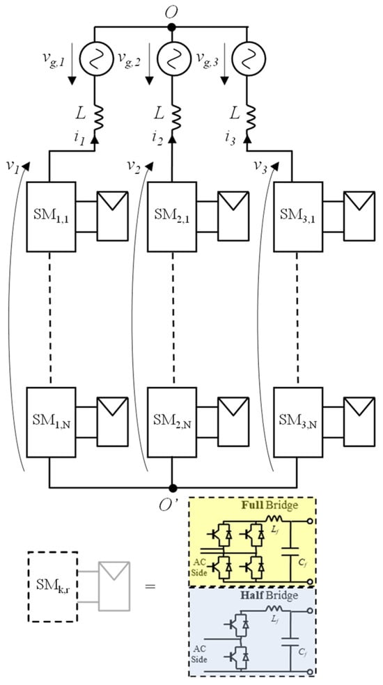
Figure 1.
MMC architecture and representative submodule (SM) configurations.
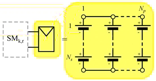
Figure 2.
PV array composed of Np parallel strings, each formed by Ns series-connected PV modules.
With reference to Figure 1, the instantaneous active power supplied by the MMC module can be expressed as:
while the active power averaged over a generic time interval can be expressed as:
If the switching frequency is neglected, at steady state both and can be assumed sinusoidal waveforms varying at the grid frequency . If the MMC modules employ the Half-Bridge configuration, exposes also a common mode DC component. Consequently, the current-voltage interaction will drive a power ripple at frequency 2f or f based on the architecture chosen for the power modules (Full-Bridge or Half-Bridge). Therefore, if is chosen accordingly to the MMC module configuration, the average active power computed as per (2) effectively filters out the power ripple.
In this context, a power-based P&O can be formulated with reference to an observation time set equal to , which also sets the rate at which the power reference is updated.
By denoting with the generic instant at which the P&O is executed, the observed variable at is set to the average slope exposed by the DC-Link voltage :
while the perturb action is formalized by the power reference update law:
is computed based on with a relay-based logic:
with , and , respectively negative and positive quantities. Sizing criteria for these quantities [28] can be effectively formulated if, with reference to the filter which connects the PV array to the correspondent MMC module, the power absorbed by the inductor over an observation time is neglected (a reasonable approximation if the resonance frequency is set to dampen the current harmonics driven by the switching frequency) and an average model over of the coupling capacitor is considered:
with and the average values over the last observation time interval of power supplied by the PV array and of the capacitor voltage.
In the power-increasing mode of the considered P&O algorithm (), there will be an observation interval for which the module power reference overshoots the connected PV array’s maximum power by , with If the P&O mode does not change and the PV maximum power remains constant, it can be assumed that in the next observation interval, the power reference will overshoot the maximum power by . The corresponding capacitor average time derivative will be:
Consequently can be set to It should be noted that, if the maximum power decreases in the second observation interval, the actual capacitor average time derivative is lower than the one supplied by (7), so that the proposed sizing of still guarantees the switching of the P&O operating mode. can be instead set based on the required P&O tracking dynamic. Indeed, by denoting with the rated power of the connected PV array, the required time by the considered P&O to track can be quantified as , i.e.,:
Given that is in the range of milliseconds while is usually in the range of seconds, which results that should be set to a small fraction of .
Conversely, in the power decreasing mode (), if is properly chosen (as discussed later in this section), there will be an observation interval for which the module power reference undershoots the PV array’s maximum power . The corresponding capacitor average time derivative will be positive. So, in this case, it is enough to set . Naturally, for to become lower than , it is needed for the time derivative of the reference power (set by ) to be lower than the time derivative of the maximum power (driven by the time derivative of the irradiance power), i.e.,:
with the normalized irradiance power. The (9) allows to set once a minimum value for (worst case condition) is provided.
This approach exploits the decoupling effect of the filter capacitor which interfaces the MMC module with the PV array: when the power requested by the MMC module exceeds the maximum power drainable from the connected PV array, the excess power is supplied by the interface capacitor, whose voltage decreases consequently at an increasing rate. Therefore, by properly sizing the control parameter (, , , ), it is possible to guarantee the stability of the maximum power tracking process with respect to strong perturbations (like sudden irradiation power variations) without significantly worsening the performance at steady state [28].
The outputs of the per-module power-based P&O technique are the module’s average reference powers , from which the MMC phase average powers can be easily derived as:
It should be noted that on each phase the module’s reference powers can be guaranteed only if the corresponding phase exhibits the reference power given by (10). The tracking of the power references is therefore articulated upon two stages: the outer stage computes the MMC phase reference voltages, which drive the phase currents to the optimal phase reference currents, which satisfy (10), while the inner stage modulates the MMC phase reference voltages in order to split the phase powers according to the module reference powers.
The overall procedure is reported in the control scheme of Figure 3, which highlights how the per-module power-based P&O drives both the grid currents control (see Section 3) and the MMC modulation (see Section 4).
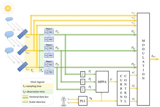
Figure 3.
Control scheme of the considered system.
3. MPPA-Based Current Control
With reference to Figure 1, the Kirchhoff Voltage Law (KVL) applied to the k-th phase gives:
with the converter phase voltage, the grid phase voltage, the phase current, and the displacement voltage. and are the boost inductance and the associated parasitic resistance.
By exploiting the well-known space vector transformation, the KVL can be synthetically reformulated as:
From (12) it results that the instantaneous value of the grid current space vector can be effectively controlled by properly driving the converter voltage space vector. In particular, by denoting with the reference current space vector, the reference voltage space vector is computed as:
with the output of a Proportional Integral Resonant controller acting on the error -. The resonant component, tuned on the grid angular frequency , guarantees zero tracking error on both fundamental positive and negative current sequences.
Under sinusoidal steady-state conditions at angular frequency , and can be decomposed into the corresponding positive and negative sequences. If the grid voltages are assumed symmetrical, exposes just the positive sequence. On the other hand, if the active powers are distributed unevenly across the grid phases, exposes both the positive and negative sequences:
with the sequences amplitudes and the correspondent phase angles.
The k-th phase instantaneous active power averaged over the grid voltages period T:
can be conveniently expressed with respect to the voltage/current sequences:
with and .
Therefore, the constraints , with the k-th phase reference power, reduce to the following set of equations:
which represents a non-linear system of three equations in the four unknown quantities. , , and , i.e., there are infinite combinations of positive/negative current sequences which satisfy the active powers constraint. The additional freedom degree can be exploited to impose an additional optimal condition. In this work, a Maximum Power Per Ampere (MPPA) strategy is employed, i.e., the power tracking is achieved with the combination of positive and negative sequences that minimizes the equivalent current RMS , with the k-th phase current RMS. As reported in [29], the MPPA solution is characterized by the following amplitudes/phase angles:
with the total reference power and the hence defined power unbalancing space vector.
By denoting with the instantaneous phase angle of , which can be estimated by Phase Locked Loop (PLL) operating on the line-to-line voltages, the reference current space vector can be finally written as:
4. Proposed Modulation Technique
In the context of a digital control operating at a sampling time set to , the modulation is performed on each MMC k-th phase by properly driving at rate the corresponding modulation block (which computes the relevant MMC modules’ duty-cycles) with the corresponding per-module phase power references (which are updated each and are the outputs of the described P&O algorithm). The inputs of modulation blocks are, besides the set of the modules’ power references updated at rate, the phase voltage references and the DC-Link modules’ voltages , both updated at rate.
While for each phase modulation block, the corresponding power references are updated at the common rate, it is convenient, as discussed later, to introduce a per modulation block time offset, i.e., to apply a time delay between the generic start instant of the observation time interval of the first phase modulation block and the corresponding instants , of the second and third phases. To keep time coherence between the modulation procedure and the P&O procedure, the same time offset is applied to the per-phase P&O blocks, in order to equalize the start instants of the modulation blocks with the update instants of the corresponding P&O blocks. At the observation time interval’ start instant of k-th modulation block, the corresponding reference powers are converted into reference energies and the energies exchanged by the modules are set to zero. The modules are then sorted based on the energy error such as:
with the remapped index.
The procedure will then proceed as per the following constraints:
- ▪
- Only one module will be driven with a fractional duty-cycle;
- ▪
- For Full-Bridges architecture, all the modules’ duty cycles will be either positive or negative.
Based on these assumptions, all the final module reference voltages will be either positive or negative, and their amplitude will be either equal to the corresponding DC-Link voltage or zero, with the exception of the module subject to a fractional duty-cycle.
Therefore, the following positions can be made:
with the index of the module driven with a fractional duty cycle.
The exchanged energies will then be updated only for the activated modules. The variation of the exchanged energy can be approximated with for the modules driven with a unitary duty cycle, with for the module driven with a fractional duty cycle. While for the generic module, the error amplitude will either increase or decrease based on the sign of the product , the application of (3) ensures that the higher convergence priority is always granted to the module characterized by the maximum error. Since the driving stage ensures that the total energy exchanged by the k-th phase will be set by the end of the observation interval, to , the energies exchanged by the modules will also be constrained to converge to the corresponding references.
The residual energy errors will depend mainly on the resolution with which the energies are adjusted in the last sampling time intervals. Since the resolution is linked to the current value, it would be convenient to synchronize the time interval of each modulation block with the corresponding current zero crossings. This condition can be easily achieved if the current system is symmetrical. It is enough to set:
and to link to the zero-crossing time instant of the first phase grid voltage.
Conversely, when the system current is asymmetrical, i.e., when an unbalanced set of phase power references is considered, the synchronization of the start instant of the modulation blocks with the current zero crossing instants would require to update continuously updating the time delays based on the operation mode and would therefore significantly complicate the whole algorithm. For this reason, the time delays are always kept at . The flowchart of the overall procedure is reported in Figure 4.
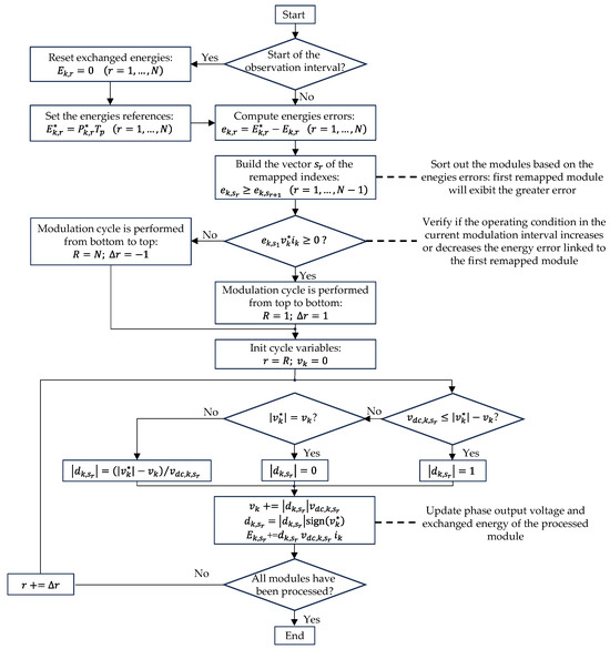
Figure 4.
Flowchart of the modulation procedure.
5. Simulation Results
The proposed modulation technique has been validated through an extensive simulation performed in the MATLAB 2025a Simulink environment. The main parameters of the considered power architecture are reported in Table 1, while Table 2 shows the used controller settings. In order to further stress the control system, even if the Full-Bridge architecture has been chosen for the MMC modules, the observation time interval Tp has been set to 20 ms versus the minimum feasible one of 10 ms. The simulation has been performed based on an assigned time profile of modules’ irradiance powers . The time profile has been set with the aim of testing the maximum power tracking effectiveness of the algorithm under strong variation of the power irradiances in unbalanced conditions.

Table 1.
Main system parameters.
Table 2.
Main control parameters.
From the simulation start instant t = 0 s up to t = 26 s all the power irradiances are kept constant and equal to 1000 Wm−2. A dynamic irradiance disturbance is then introduced, simulating the partial shading effect caused by a moving cloud. To comprehensively evaluate the performance of the proposed algorithm, the control has been tested under a significant partial shading scenario specifically designed to stress the system in terms of both tracking dynamics, due to a pronounced irradiance gradient, and unbalanced operating conditions, characterized by substantial irradiance differences among phase modules and across the converter phases. The effect of the partial shading condition is to unbalance the maximum power operating points of the MMC PV sub-arrays. So partial shading is automatically managed by the P&O architecture, which operates on a per-module basis. In particular, the irradiance power of the first module of the first phase decreases linearly at a rate of 100 Wm−2s−1 until reaching 500 W/m2 at t = 31 s. This irradiance drop is sequentially applied to the remaining modules of the first phase with a one-second delay and propagates to the remaining phases with a one-second delay between the first module of the considered phase and the last module of the previous phase. A second dynamic irradiance disturbance is considered at t = 40 s: the irradiance power of the first module of the first phase increases linearly at a rate of 100 Wm−2s−1 until reaching 1000 W/m2 at t = 45 s. Again, the irradiance disturbance propagates across the subsequent modules with a one-second delay.
Figure 5 shows across three columns the time behavior of the first, second, and third phase considered quantities. The top row plots depict the time behavior of the power references and of the irradiance powers, the middle and the bottom row plots show respectively the time behavior of the modules’ DC-Link voltages and of the corresponding average slopes. All the reported quantities have been normalized with respect to either their rated value or to an equivalent rated value.
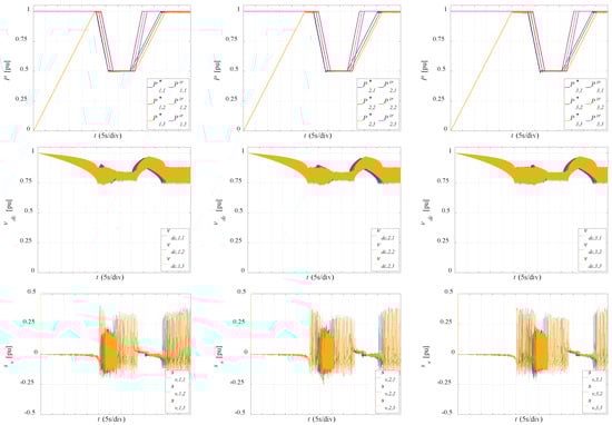
Figure 5.
Modules reference/irradiance powers and DC-Link voltages behavior in the whole simulation.
As reported in the top plots, starting from t = 0 s, the P&O takes around 25.4 s to stabilize the system near the maximum power point. This result is coherent with the setting chosen for (80 W), which translates to a positive power slope of about 4 kWs−1. This value, as confirmed by the bottom plots of Figure 5, guarantees that the tracking of the maximum power is performed at almost zero DC-Link voltage slope when the power drained from the module is lower than the maximum drainable power, avoiding therefore a switching of the hysteresis controller to . Conversely, the dynamic of the maximum power tracking in these conditions is negatively affected. Given that PV systems operate for most of the time in steady state with moderate irradiance power variations, the obtained performance negligibly affects the energy extracted. It can also be observed how, while the DC-Link voltages are characterized by a strong ripple (which, being generated by the interaction between module current and voltage, occurs at 100 Hz), the corresponding estimated slopes filter out completely the inherent ripples. This is expected, given that the voltage variations are estimated at the observation time rate. With reference to the DC-Link voltages, it can be noted that, while the power references change from zero to the maximum values, their mean value decreases from the open circuit voltage VOC to the maximum power voltage VM, while their ripple increases as the drained power increases.
Starting from the instant at which the maximum power is reached for all the MMC modules (around 25.4 s), the P&O stabilizes the operating condition by continuously triggering between and , which results in DC-Link voltage slopes varying between negative and positive values. The corresponding power references are consequently kept constant until the first disturbance occurs at t = 26 s in the irradiance powers.
It can be noted that the P&O follows closely the power irradiances when they start decreasing at 26 s. The result is coherent with the setting chosen for (−1000 W), which translates to a negative power slope of about −50 kWs−1, versus the derivative of −10 kWs−1 of the module maximum power driven by the decrease of the power irradiance at 100 Wm2s−1.
Indeed, in this operating condition, the power reference step decreases cause the corresponding average voltage slope to become positive, therefore triggering the P&O hysteresis action, which consequently switches continuously between and , as it results from the relevant plots. It is worth noting that, in the time interval in which the irradiance powers decrease, the module’s power references can be viewed as a symmetrical set of time variables delayed by the time offset applied to the corresponding power disturbance. This behavior highlights that the P&O procedures are effectively decoupled not just across the modules belonging to the same phase, but also across the different phases.
The results obtained in correspondence with the second disturbance, which starts at t = 40 s, confirm the effectiveness of the control. It is worth noting that in this case, the P&O is not able to follow closely the irradiance power, since, as already stated, the power references are increased at 4 kWs−1 while the derivative of the modules’ maximum powers driven by the variation of the irradiance powers equals 10 kWs−1. Indeed, in the time interval in which the generic irradiance power increases, the corresponding average voltage slope is almost zero, confirming that no switching occurs in the P&O relay logic.
To highlight the operation of the proposed modulation, the time behavior of the modules’ extracted energies and of the grid currents in an observation time interval has also been reported. Figure 6 shows the result at around 25 s (the power references of all modules are kept close to their rated value), while Figure 7 shows the result at around 31 s (power references of the first and second phase modules are strongly unbalanced, while power references of the third phase module are kept close to their rated value). Again, the time behavior of the first, second, and third phase quantities is spanned across three columns. Top plots depict the time behavior of the modules’ extracted energies and corresponding energy references. Bottom plots show the grid currents’ time behavior. It should be noted that, as stated in Section 4, the observation time interval of each phase starts at the corresponding grid voltage zero crossing, i.e., the time origin in the second and third columns is delayed by and with respect to the first column, the time origin.
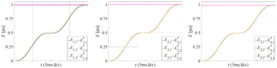
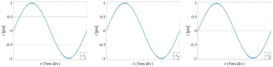
Figure 6.
Modules extracted energy and current behavior in an observation time interval of around 25 s.
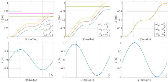
Figure 7.
Modules extracted energy and current behavior in an observation time interval at around 31 s.
The presented results confirm that the modulation technique is able to split effectively across the controlled modules on each phase, the corresponding injected power based on the individual module power references, even where the power references are strongly unbalanced. In this case, the grid currents can expose a strong negative sequence, as shown in the bottom plots of Figure 6: the corresponding grid currents are characterized by different amplitudes as well as significant phase angle displacements with respect to the phase angles of the positive sequence.
The presented results demonstrate that the proposed power-based control framework operates reliably and effectively. It is worth noting that the primary goal of this work is to validate the feasibility of a novel control approach in which each MMC submodule receives a direct power reference, instead of the conventional voltage reference adopted in state-of-the-art MPPT schemes. This formulation enables maximum power tracking without measuring PV-side currents, representing a conceptual shift from traditional implementations. Therefore, this paper focuses on demonstrating the effectiveness and stability of the proposed method as a preliminary step. A detailed quantitative comparison with conventional modulation and MPPT strategies will be presented in a subsequent study, supported by experimental implementation.
6. Conclusions
This paper presented an advanced modulation strategy for Modular Multilevel Converters (MMCs) used in grid-connected photovoltaic (PV) systems, with the specific objective of maximizing power extraction at the module level under uneven and time-varying irradiance conditions. The proposed dual time-scale control approach combines a per-module Perturb and Observe (P&O) algorithm with a selective modulation mechanism, ensuring both accurate Maximum Power Point Tracking (MPPT) and energy balancing across submodules.
The effectiveness of the proposed control technique was rigorously validated through detailed simulations conducted in a MATLAB/Simulink environment. The test bench included full electrical modeling of MMCs, PV arrays, and control layers, closely reflecting realistic operating conditions. The simulations accounted for dynamic irradiance disturbances, such as those caused by moving clouds, by applying time-delayed, sequential irradiance drops and rises across all modules and phases.
Quantitatively, the system demonstrated the ability to reach steady-state MPPT conditions in approximately 25.4 s under uniform irradiance, consistent with the defined positive power slope of 4 kW/s and the corresponding P&O resolution settings. During disturbance events, such as the irradiance drop from 1000 W/m2 to 500 W/m2, the system accurately tracked power variations with a response slope of −50 kW/s, outperforming the irradiance derivative of −10 kW/s per module. Even when highly unbalanced conditions occurred across phases, the proposed modulation strategy maintained sinusoidal grid currents and adhered to reference power distributions, with energy tracking errors confined within acceptable bounds determined by the resolution of the final modulation steps.
It is important to emphasize the computational and modeling challenges encountered during the validation process. The simulation model featured over 270 PV modules (distributed in series-parallel configurations across three phases), three-level MMC topologies with Full-Bridge submodules, and sub-millisecond sampling rates (100 µs), leading to a highly nonlinear, tightly coupled system with significant computational load. Despite these complexities, the proposed strategy exhibited excellent robustness and performance, proving suitable for deployment in real-world PV installations.
In summary, the developed modulation technique offers a scalable, high-performance control solution for MMC-based PV systems operating under non-uniform environmental conditions. Its ability to decouple MPPT from global converter constraints, combined with accurate power tracking performed at a reduced switching frequency, makes it an attractive candidate for future smart-grid-connected renewable systems. The main purpose of this study is to validate the feasibility of a new control principle in which each MMC submodule is assigned a power reference rather than a voltage reference, as commonly done in traditional MPPT schemes. This formulation enables effective power tracking without measuring PV currents, offering a conceptual advantage over existing methods.
Although the experimental validation of the proposed approach will be the subject of future work, the preparation of the experimental setup is already underway. Specifically, a scaled-down MMC connected to PV simulators is being assembled, and the control algorithm has already been implemented on a Texas Instruments C2000 F28379D microcontroller (Texas Instruments, Dallas, TX, USA). In this setup, each module is driven by its own microcontroller, while all controllers communicate via a dual SPI interface with a master controller in a slave–master configuration. The slave controllers provide local measurements and receive duty cycles from the master, where the control algorithm is executed. Preliminary measurements indicate an average execution time of approximately 20 μs, with an additional 30 μs required for SPI communication. These promising results and the ongoing development of the experimental platform pave the way for a comprehensive validation and performance assessment of the proposed control strategy, which will be presented in future work.
Author Contributions
Conceptualization, A.D. and G.B.; methodology, D.I.; software, G.B.; validation, D.I. and S.M.; formal analysis, G.B.; investigation, A.D.; resources and visualization, I.S.; data curation, S.M.; writing—original draft preparation, D.I.; writing—review and editing, A.D. and G.B.; supervision, A.D.; project administration, G.B.; funding acquisition, A.D. All authors have read and agreed to the published version of the manuscript.
Funding
This research was supported by Spoke 13—Flagship 2024—LINE B—2° Edition High Integrated Hybrid Smart Plug and was funded by the European Union Next-Generation EU (Piano Nazionale di Ripresa e Resilienza (PNRR)–Missione 4 Componente 2, Investimento 1.4–D.D. 1033 17 June 2022, CN00000023). This manuscript reflects only the authors’ views and opinions—neither the European Union nor the European Commission can be considered responsible for them.
Data Availability Statement
The original contributions presented in this study are included in the article. Further inquiries can be directed to the corresponding author.
Conflicts of Interest
The authors declare no conflict of interest.
References
- Peralta, J.; Saad, H.; Dennetière, S.; Mahseredjian, J.; Nguefeu, S. Detailed and Averaged Models for a 401-Level MMC–HVDC System. IEEE Trans. Power Del. 2012, 27, 1501–1508. [Google Scholar] [CrossRef]
- Franquelo, L.G.; Rodriguez, J.; Leon, J.I.; Kouro, S.; Portillo, R.; Prats, M.A. The Age of Multilevel Converters Arrives. IEEE Ind. Electron. Mag. 2008, 2, 28–39. [Google Scholar] [CrossRef]
- Viatkin, A.; Ricco, M.; Mandrioli, R.; Kerekes, T.; Teodorescu, R.; Grandi, G. A Novel Modular Multilevel Converter Based on Interleaved Half-Bridge Submodules. IEEE Trans. Ind. Electron. 2023, 70, 4512–4525. [Google Scholar] [CrossRef]
- Rohner, S.; Bernet, S.; Hiller, M.; Sommer, R. Modulation, Losses, and Semiconductor Requirements of Modular Multilevel Converters. IEEE Trans. Ind. Electron. 2010, 57, 2633–2642. [Google Scholar] [CrossRef]
- Li, B.; Zhou, S.; Xu, D.; Finney, S.J.; Williams, B.W. A Hybrid Modular Multilevel Converter for Medium-Voltage Variable-Speed Motor Drives. IEEE Trans. Power Electron. 2017, 32, 4619–4630. [Google Scholar] [CrossRef]
- Saad, H.; Ould-Bachir, T.; Mahseredjian, J.; Dufour, C.; Dennetiere, S.; Nguefeu, S. Real-Time Simulation of MMCs Using CPU and FPGA. IEEE Trans. Ind. Electron. 2015, 62, 5491–5501. [Google Scholar] [CrossRef]
- Kouro, S.; Cortes, P.; Vargas, R.; Ammann, U.; Rodriguez, J. Model Predictive Control—A Simple and Powerful Method to Control Power Converters. IEEE Trans. Ind. Electron. 2009, 56, 1826–1838. [Google Scholar] [CrossRef]
- Qin, J.; Saeedifard, M. Predictive Control of a Modular Multilevel Converter for a Back-to-Back HVDC System. IEEE Trans. Power Del. 2012, 27, 1538–1547. [Google Scholar]
- Barcellona, S.; Barresi, M.; Piegari, L. MMC-Based PV Three-Phase System with Distributed MPPT. IEEE Trans. Energy Convers. 2022, 37, 5129–5140. [Google Scholar] [CrossRef]
- Bakir, Y.N.; de Pablo, S.; Martinez-Rodrigo, F.; Aljawary, Z.A.; Lucas, L.C.H.-D. Nearest Vector Control Method Applied to an MMC for PV Generation. Energies 2024, 17, 1795. [Google Scholar] [CrossRef]
- Bhutto, M.U.; Soomro, J.B.; Ali, K.H.; Memon, A.A.; Ansari, J.A.; Alamri, B.; Alqarni, M. Innovative Model Predictive Control for HVDC: Circulating Current Mitigation and Fault Resilience in Modular Multilevel Converters. Front. Energy Res. 2024, 12, 1345032. [Google Scholar] [CrossRef]
- Lesnicar, A.; Marquardt, R. An Innovative Modular Multilevel Converter Topology Suitable for a Wide Power Range. In Proceedings of the IEEE PESC, Bologna, Italy, 23–26 June 2003; pp. 172–177. [Google Scholar]
- Rodriguez, J.; Bernet, S.; Steimer, P.K.; Lizama, I.E. A Survey on Neutral-Point-Clamped Inverters. IEEE Trans. Ind. Electron. 2010, 57, 2219–2230. [Google Scholar] [CrossRef]
- Xiao, B.; Hang, L.; Mei, J.; Riley, C.; Tolbert, L.M.; Multilevel, B. Modular Cascaded H-Bridge Multilevel PV Inverter with Distributed MPPT for Grid-Connected Applications. IEEE Trans. Ind. Appl. 2015, 51, 1722–1731. [Google Scholar] [CrossRef]
- Kouro, S.; Malinowski, M.; Gopakumar, K.; Pou, J.; Franquelo, L.G.; Wu, B.; Rodriguez, J.; Pérez, M.A.; Leon, J.I. Recent Advances and Industrial Applications of Multilevel Converters. IEEE Trans. Ind. Electron. 2010, 57, 2553–2580. [Google Scholar] [CrossRef]
- Patel, H.; Agarwal, V. Maximum Power Point Tracking Scheme for PV Systems Operating Under Partially Shaded Conditions. IEEE Trans. Ind. Electron. 2008, 55, 1689–1698. [Google Scholar] [CrossRef]
- Marquardt, R. Modular Multilevel Converter: A Universal Concept for HVDC Networks and Extended DC-Bus Applications. In Proceedings of the 2010 International Power Engineering Conference (IPEC), Sapporo, Japan, 21–24 June 2010; pp. 502–507. [Google Scholar]
- Wang, J.; Wang, P. Power Decoupling Control for Modular Multilevel Converter. IEEE Trans. Power Electron. 2018, 33, 9296–9309. [Google Scholar] [CrossRef]
- Mohamed, F.; Wasti, S.; Afshar, S.; Macedo, P.; Disfani, V. MMC-Based Distributed Maximum Power Point Tracking for Photovoltaic Systems. In Proceedings of the IEEE Power & Energy Society General Meeting (PESGM), Montreal, QC, Canada, 2–6 August 2020; pp. 1–5. [Google Scholar]
- Balamurugan, S.; Palanisamy, R.; Karthikeyan, B. Experimental Investigation of Modular Multilevel Converter Using Space Vector PWM. J. Electr. Eng. Technol. 2023, 19, 229–240. [Google Scholar]
- Wu, X.; He, L.; Li, Y.; Shuai, Z. Low-Frequency Oscillations in MMC-MVDC Systems with High PV Penetration: Modelling and Assessment. IET Power Electron. 2024, 17, 492–504. [Google Scholar] [CrossRef]
- Xu, J.; He, G.; Liu, Y.; Tang, S.; Xie, D.; Chen, M. Analysis and improvement of the reactive power cascade control strategy for MMC-HVDC receiving-end converter connected to weak grid. IET Gener. Transm. Distrib. 2024, 18, 3137–3148. [Google Scholar] [CrossRef]
- Jouybary, H.S.; Khaburi, D.A.; El Hajjaji, A.; Mabwe, A.M. Optimal Sliding Mode Control of Modular Multilevel Converters Considering Control Input Constraints. Energies 2025, 18, 2757. [Google Scholar] [CrossRef]
- Barcellona, S.; Barresi, M.; Piegari, L. MMC-Based PV Single-Phase System with Distributed MPPT. Energies 2020, 13, 3964. [Google Scholar] [CrossRef]
- Alotaibi, S.; Darwish, A. Modular Multilevel Converters for Large-Scale Grid-Connected Photovoltaic Systems: A Review. Energies 2021, 14, 6213. [Google Scholar] [CrossRef]
- Barresi, M.; De Simone, D.; Ferri, E.; Piegari, L. Variable Submodule Voltage Control for Enhanced Efficiency in DAB-Integrated Modular Multilevel Converters. Energies 2025, 18, 4096. [Google Scholar] [CrossRef]
- Farajdadian, S.; Hosseini, S.M.H. DMPPT control of photovoltaic systems under partial shading conditions based on optimized neural networks. Soft Comput. 2024, 28, 4987–5014. [Google Scholar] [CrossRef]
- Brando, G.; Dannier, A.; Rizzo, R. A Sensorless Control of H-Bridge Multilevel Converter for MPPT in Grid Connected PV Systems. In Proceedings of the International Conference on Clean Electrical Power (ICCEP), Capri, Italy, 21–23 May 2007; pp. 789–794. [Google Scholar]
- Brando, G.; Dannier, A.; Del Pizzo, A. An Optimized Control of PWM-Rectifiers with Predicted Variable Duty-Cycles. In Proceedings of the IEEE International Symposium on Industrial Electronics, Cambridge, UK, 30 June–2 July 2008; pp. 68–73. [Google Scholar]
Disclaimer/Publisher’s Note: The statements, opinions and data contained in all publications are solely those of the individual author(s) and contributor(s) and not of MDPI and/or the editor(s). MDPI and/or the editor(s) disclaim responsibility for any injury to people or property resulting from any ideas, methods, instructions or products referred to in the content. |
© 2025 by the authors. Licensee MDPI, Basel, Switzerland. This article is an open access article distributed under the terms and conditions of the Creative Commons Attribution (CC BY) license (https://creativecommons.org/licenses/by/4.0/).