Abstract
The increasing penetration of renewable energy and electric vehicles (EVs) has intensified the need for grid-forming (GFM) inverters capable of supporting frequency and voltage stability. Virtual Oscillator Control (VOC) has recently emerged as a promising time-domain GFM strategy due to its fast dynamics and autonomous synchronisation capability. This paper presents a comprehensive analysis of recent VOC developments, focusing on the Andronov–Hopf Oscillator (AHO) and its variants. A comparative overview of different VOC structures highlights their capabilities in providing essential services such as dispatchability, fault ride-through (FRT), virtual inertia, and damping. A generalised small-signal state-space model is developed to assess the influence of virtual inertia, grid impedance, and control parameters on transient performance, which is essential for optimal parameter design and controller tuning in various applications. Experimental validation using a 2.5 kVA single-phase inverter shows excellent agreement with theoretical predictions. The results confirm that while increased virtual inertia enhances frequency stability, it also introduces oscillations that can be effectively mitigated through damping enhancement. Furthermore, the experiments demonstrate that advanced AHO-based strategies successfully deliver vehicle-to-grid (V2G) and vehicle-to-home (V2H) services, confirming their practical applicability in future EV-integrated and renewable-rich power systems.
1. Introduction
The rapid growth of electric vehicles (EVs) and the accelerating integration of renewable energy sources are transforming the operational landscape of modern power systems. This shift away from conventional power plants, which have provided grid stability through the rotational inertia of synchronous generators (SGs), presents significant challenges to maintaining a reliable and resilient power system. The resulting decrease in system inertia makes the grid more vulnerable to frequency and voltage fluctuations. To address these challenges, new sources of grid stability must be established, capable of providing essential ancillary services such as frequency regulation, voltage support, and operating reserves [1].
Battery energy storage systems (BESS), particularly those embedded in EVs, are poised to play a key role in this context. Vehicle-to-grid (V2G) and vehicle-to-home (V2H) functionalities transform EVs from a pure load into a dispatchable distributed energy resource [2,3]. This transformation enables EVs to provide essential ancillary services to the grid and supply backup power to homes during outages. However, to contribute effectively, their inverters must evolve from traditional grid-following control, which acts as a current source dependent on a strong grid, to advanced grid-forming (GFM) control. GFM inverters function as voltage sources, enabling stand-alone operation and emulating the stabilising behaviour of SGs. Importantly, the application of GFM control methods is not limited to EVs but is also applicable to a wide range of inverter-based resources, such as photovoltaic and wind turbine systems, where they can enhance stability, improve power quality, and support grid resilience.
Among various GFM techniques, Virtual Oscillator Control (VOC) has gained attention for its superior dynamic performance. Early VOC strategies were designed to emulate nonlinear oscillators such as the dead-zone oscillator (DZO) [4] and Van der Pol oscillator (VDPO) [5]. While these oscillators offer certain benefits, their high harmonic content and lack of dispatchability limit their suitability for grid-connected applications. To address these challenges, the Andronov–Hopf oscillator (AHO) has recently been introduced as a harmonic-free and dispatchable VOC strategy [6,7]. However, while promising, existing AHO strategies suffer from critical limitations that hinder their practical application. Early implementations like the unified VOC (uVOC) demonstrated basic GFM capability but lacked virtual inertia [8]. Subsequent attempts to incorporate virtual inertia into the AHO (VI-AHO) dynamics inadvertently reduced the system’s damping factor, leading to undesirable oscillatory behaviour [9,10]. To address this, a feedforward damping improvement strategy (Da-AHO) has been proposed, which provides sufficient damping while maintaining adequate virtual inertia [11]. However, all these strategies suffer from a voltage-dependent active power loop (APL) droop coefficient, limiting their ability to maintain consistent grid support during disturbances and resulting in power-sharing inaccuracies. To address this, an enhanced AHO (EAHO) has been proposed in [12], where the APL droop is completely independent of the voltage.
Although various VOCs have been reviewed in the literature with a focus on their structures [7,13,14,15], a comparative overview of recent VOC advancements and their ancillary services remains lacking. Furthermore, a gap exists in their small-signal stability analysis. While some recent studies have investigated the VOC’s small-signal stability [7,14,16], these analyses have not considered the impact of virtual inertia, which fundamentally alters the system dynamics to a second-order system and can significantly affect transient performance.
To address these gaps, this paper, which is an extended version of [17], presents an overview of recent advancements in ancillary services provided by different VOC strategies. The main contributions of this article are summarised below:
- (1)
- An overview of recent advancements in various VOC strategies, with a primary focus on the AHO structure, which has gained significant attention for its superior features.
- (2)
- Development of a generalised state-space model to facilitate small-signal analysis of VOCs.
- (3)
- Investigation of the effects of virtual inertia, control parameters, and grid impedance parameters on the transient performance of the AHO, based on the proposed state-space model. This analysis provides practical guidance for control parameter selection in different application scenarios.
- (4)
- Experimental validation of the theoretical findings using extensive tests on a 2.5 kVA single-phase inverter.
The rest of this paper is organised as follows. Section 2 presents an overview of VOC structures and ancillary services. Section 3 introduces the generalised state-space model and investigates the effect of different parameters on transient performance, followed by experimental validation in Section 4. Finally, Section 5 concludes the paper.
2. VOC Structures and Their Ancillary Services
Figure 1 depicts the historical development of VOC strategies. As shown, the DZO was the first oscillator implemented for GFM applications. More recent studies, however, have shifted attention toward improving the AHO to better support ancillary services.
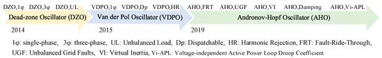
Figure 1.
VOC development timeline. DZO,1φ [4], DZO,3φ [18], DZO,UL [19], VDPO,1φ [5,20], VDPO,Dp [21,22], VDPO,HR [23], AHO,FRT [8], AHO,UFG [24], AHO,VI [9,10], AHO,Damping [11], and AHO,Vi-APL [12].
2.1. Dead-Zone Oscillator (DZO)
Figure 2 illustrates the general structure of a DZO for a single-phase BESS. In this figure, Lf, Rf, and Cf are the filter inductance, its parasitic resistance, and the filter capacitance, respectively. ZL is the local load, and Lg and Rg denote the grid impedance. The DC link is modelled by Cdc and Vdc, denoting its capacitance and voltage, vpcc represents the voltage at the point of common coupling, and i is the inverter output current. The DZO is realised as an RLC circuit connected in parallel with two current sources [14]. In this framework, iL is the inductor current, Ki and Kv represent the current and voltage gains, , and vc is the capacitor voltage. The nonlinear function f (vc, iL) is expressed in Equation (1), where σ and φ are the control parameters [4].
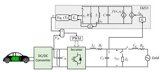
Figure 2.
Single-phase inverter with DZO [4].
In this oscillator, the output voltage (v) is obtained as:
where φ determines the droop functionality, which is zero for resistive and π/2 for inductive networks. In this work, φ = π/2 is adopted.
Importantly, it has been shown that droop functionality is inherently embedded within the DZO dynamics, as expressed in Equation (4), where mp and mq denote the active and reactive power droop coefficients, respectively [13].
The DZO was originally proposed in [4] as the first time-domain oscillator-based GFM control method for synchronising parallel single-phase inverters operating in stand-alone mode. Since then, its application has been extended to three-phase networks and unbalanced load scenarios [18,19]. Furthermore, a systematic tuning methodology for oscillator parameters was presented in [25].
Despite these advancements, the DZO lacks dispatchability, meaning that power setpoints cannot be explicitly assigned in grid-connected operation. Moreover, its dynamic model does not incorporate virtual inertia, thereby constraining its ability to provide frequency stability support.
2.2. Van Der Pol Oscillator (VDPO)
As illustrated in Figure 1, the VDPO was initially introduced for single-phase GFM applications operating in stand-alone mode [5,20]. A small-signal comparison between VDPO and conventional droop control revealed that both strategies achieve comparable steady-state performance. However, VDPO demonstrates a significantly faster response under large frequency and voltage amplitude variations [26].
The VDPO control structure closely resembles that of the DZO (see Figure 2), while its nonlinear function and corresponding droop coefficients are expressed in Equations (5) and (6):
where α is the VDPO control parameter, σ = −1/R and β = 3α/(σKv2) [5].
Several studies have focused on improving the dispatchability of VDPO. In [21], proportional–integral (PI) controllers were introduced to enable power reference tracking by modulating the input current gain. Moreover, a hierarchical control framework was proposed in [22] to facilitate seamless transitions between stand-alone and grid-connected operation. Despite these improvements, a key limitation of VDPO lies in the generation of third-order voltage harmonics, which hinders its suitability for grid-connected applications. To address this issue, a selective harmonic suppression method employing virtual impedance was proposed in [23].
Despite all these enhancements, the VDPO does not inherently provide virtual inertia or additional damping capabilities, which restricts its applications where enhanced frequency stability support is required.
2.3. Andronov–Hopf Oscillator
The AHO is a dispatchable oscillator that generates harmonic-free voltage [6,7]. Figure 3 illustrates its control structure, governed by the following equations [6]:
where ꞷ0 denotes the nominal angular frequency, ξ is the convergence speed to steady-state, V0 is the nominal value of voltage magnitude (V). In single-phase systems, since only the α-axis current is physically available, the current component iβ is usually generated by a second-order generalised integrator-based quadrature signal generator (SOGI-QSG) [2].
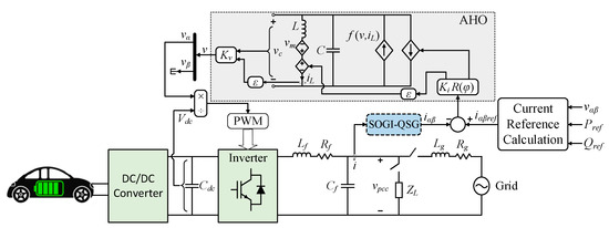
Figure 3.
Single-phase inverter with AHO [6].
As with other oscillators, droop functionality is inherently embedded within the AHO dynamics, with coefficients expressed as Equation (9) [6]:
The uVOC strategy, shown in Figure 4, extends the AHO framework to both single-phase and three-phase systems.
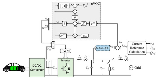
Figure 4.
Single-phase inverter with uVOC [8].
A uVOC-based inverter can operate in either GFM or grid-following mode and is equipped with fault ride-through (FRT) capability [8]. Furthermore, to maintain synchronisation during unbalanced grid faults, a double synchronous uVOC was proposed in [24]. The uVOC control law and its droop coefficients are described in Equations (10) and (11):
where μ denotes the convergence speed to the steady-state [8].
Recent developments have sought to incorporate virtual inertia into the AHO to enhance its suitability for renewable-rich power grids. Early implementations [27,28,29] achieved this by adjusting reference power in response to frequency variations. However, such approaches rely on derivative terms, which amplify noise. More recently, inertia has been realised by applying a low-pass filter (LPF) to the calculated active and reactive powers [9], or alternatively, through a resonant controller for the current error that provides comparable inertial behaviour [10]. Like other inertia-providing GFM methods, the AHO with virtual inertia can be modelled as a standard second-order dynamic system. Excessive inertia, however, can lead to high overshoot (OS) and power oscillations, potentially damaging power electronic devices. To address this, a feedforward damping strategy was proposed in [11], which reduces oscillations without compromising inertia or droop performance.
The transient stability of the uVOC has been analysed under both current-constrained and unconstrained operating conditions [30]. When compared with conventional droop control, the AHO exhibits superior transient stability during large grid disturbances [31]. Further improvements have been achieved either by modifying its control structure [32] or through optimisation of its control parameters [33].
Ongoing research has further advanced the capabilities of the AHO. An adaptive pre-synchronisation method was proposed in [34] to limit inrush currents during transitions caused by grid parameter variations. In [35], an optimisation algorithm for parameter selection of AHO has been proposed to reduce the initial response time of the inverter. For accurate active power tracking and effective reactive power regulation, [36] introduced an adaptive method that adjusts the nominal AHO voltage based on estimated grid impedance. Additionally, a dq-reference-frame control strategy was recently developed in [37], providing enhanced power tracking and improved dynamic response for VOC applications. A common limitation of conventional VOC strategies lies in their voltage-dependent APL droop coefficient. This dependency restricts grid support during disturbances and can result in power-sharing inaccuracies. To overcome this issue, the EAHO was proposed in [12]. In the EAHO, the APL droop coefficient is rendered completely independent of voltage, thereby improving active and reactive power support during frequency and voltage disturbances and significantly enhancing transient stability.
2.4. Comparison Between Different VOC Strategies
Table 1 summarises the main features of different VOC strategies. All VOC structures inherently provide droop functionality; however, their ancillary service capabilities differ. The DZO offers only basic droop control and lacks dispatchability, FRT, virtual inertia, and damping. Certain VDPO variants achieve limited dispatchability through auxiliary controllers, but they still do not provide FRT or virtual inertia. In contrast, AHO-based strategies enable dispatchability, FRT capability, and the incorporation of virtual inertia and damping, offering superior performance under grid disturbances. Moreover, the EAHO eliminates the voltage dependence of the APL droop coefficient, improving power-sharing accuracy and transient stability.

Table 1.
Comparison Between Different VOC Strategies.
3. Small-Signal Analysis
3.1. State-Space Model
This section presents a generalised small-signal model for single-phase VOC strategies in grid-connected mode through state-space formulation. In the following derivation, Δx denotes a small perturbation of the state vector from its equilibrium (Xeq), while xd and xq are the projections of x in the dq reference frame aligned with the grid voltage. Since some controllers include virtual inductance (Lvir) and virtual resistance (Rvir), the total inductance and resistance are defined as LT = Lf + Lg + Lvir and RT = Rf + Rg + Rvir, respectively. Within the low-frequency range of interest, the dynamic effects of the filter capacitor, digital delay, and PWM can be neglected [8].
By defining the oscillator’s voltage amplitude and phase as and θ = arctan(vβ/vα), the oscillator dynamic equations can be obtained from the general control law expressed in Equation (12):
where f1, f2, and f3 are nonlinear functions defined for different oscillators in Table 2 [5,6,8,13]. The parameter Tf represents the LPF time constant associated with virtual inertia, where Tf = 0 for VOCs without an inertial response.
Table 2.
Nonlinear Functions of VOC’s Dynamic Equation.
Since the dq frame is aligned with the grid voltage, the inverter output voltage can be decomposed as vd = Vcos(θ) and vq = Vsin(θ). The current dynamics and the output active and reactive powers are then described by Equations (13) and (14):
The system’s general state-space representation can therefore be written as Equation (15):
where Δx = [Δv, Δ, Δθ, Δꞷ, Δid, Δiq]T, Δu = Δvg, and A and B are Jacobian matrices. The stability of the system can be evaluated by computing the eigenvalues of matrix A, where the system is exponentially stable if all eigenvalues lie in the left half of the complex plane.
By linearising Equations (12)–(14) around the equilibrium point, the state-space representation can be obtained as Equation (15). Substituting the functions f1, f2, and f3 from Table 2 enables the formulation of the state equations for any specific VOC structure.
While some recent studies have investigated VOC small-signal stability, these analyses did not consider the impact of virtual inertia, which fundamentally alters the system dynamics into a second-order system and can significantly affect transient response. As one of the most recent and effective approaches, this study focuses on the AHO with virtual inertia (VI-AHO) proposed in [9,10]. For this configuration, the oscillator dynamics in Equation (12) can be reformulated as Equation (16):
To perform stability analysis, the equilibrium point Xeq = [Veq, 0, θeq, ωeq, Id, Iq]T is first determined by setting = = = = = 0 in Equations (12)–(14). These nonlinear equations are solved using the Newton–Raphson iteration method implemented in MATLAB (2024b) [7]. The nonlinear terms in Equation (16) are then linearised using a Taylor series expansion to obtain the Jacobian matrix A as shown in Equation (17):
Subsequently, the influence of various parameters on the dynamic behaviour of the VI-AHO is examined using the computed matrix A.
3.2. Effect of Parameters on Transient Performance
This section investigates the influence of key parameters on the transient performance of the VI-AHO system, including the virtual inertia (Tf), grid impedance (Lg and Rg), filter impedance (Lf), and control parameters (Ki and μ) for the experimental parameters listed in Table 3.
Table 3.
Experimental parameters.
The AHO control parameters are designed to sustain the nominal active (P0) and reactive power (Q0) under a 1% grid frequency deviation (Δꞷmax) and a 5% change in voltage amplitude [8,11]. As a result, the parameters μ and Ki are designed from the droop requirements as:
where Vp, max is the maximum allowable voltage amplitude [8]. Furthermore, Tf is tuned such that the maximum rate of change of frequency (RoCoF) remains below 3.5 Hz/s [11]. According to the automatic control theorem method, the relation between Tf and RoCoF can be obtained from Equation (19) [11]. Accordingly, by setting Tf = 1/(2π), RoCoF < 3.5 Hz/s is satisfied.
The grid impedance values are set as Lg = 1 mH and Rg = 1 Ω, yielding Rg/Xg = 3.2, which lies within the typical range for low- and medium-voltage networks [38]. Based on the parameters in Table 3, the resistance-to-reactance ratio is calculated as RT/XT = 0.39, confirming the suitability of inductive droop operation.
Figure 5 shows the eigenvalue map as Tf increases, thereby providing higher virtual inertia. A zoomed view of the dominant eigenvalues illustrates the detailed effect. It can be observed that the non-dominant eigenvalues (λ5,6) exhibit negligible variation with Tf, while the dominant eigenvalues (λ1,2) are significantly affected. As Tf increases, both the natural frequency (ꞷn) and damping ratio (ξ) of the dominant eigenvalues decrease, indicating that the system response becomes slower and more oscillatory due to the added inertia. For instance, Table 4 lists the calculated ξ and ꞷn for Tf = 1/(6π) s and Tf = 1/(2π) s. Approximating the system as a second-order model allows estimation of the OS and rise time (trise), which are also provided in Table 4.
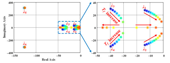
Figure 5.
Eigenvalue map when Tf changes from 1/(10π) to 1/π, where * denotes eigenvalues.
Table 4.
Transient response comparison of dominant eigenvalues for different Tf.
Figure 6 illustrates the eigenvalue map for Rg varying from 0.1 Ω to 1 Ω. The results show that λ5,6 shift leftward, moving further from the imaginary axis, while the dominant eigenvalues change only slightly, moving marginally closer to the imaginary axis. This indicates that Rg has a minimal effect on the dominant mode dynamics and thus only slightly influences the overall transient performance.
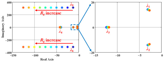
Figure 6.
Eigenvalue map when Rg changes from 0.1 Ω to 1 Ω, where * denotes eigenvalues.
Figure 7 presents the eigenvalue map as Lg increases from 1 mH to 10 mH. The results show that eigenvalues λ3 and λ5,6 move closer to the imaginary axis, indicating a slower dynamic response. Additionally, the ξ of the dominant eigenvalues (λ1,2) increases with higher Lg, implying a better-damped response. Consequently, increasing Lg leads to longer trise and reduced OS, thereby improving damping but reducing response speed.
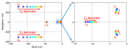
Figure 7.
Eigenvalue map when Lg changes from 1 mH to 10 mH, where * denotes eigenvalues.
The effect of varying Lf is shown in Figure 8. Similar to the effect of Lg, increasing Lf results in a slower but better-damped response, characterised by lower OS. However, instability is observed when Lf = 1 mH, as the system eigenvalues cross into the right half-plane. Therefore, a minimum 2 mH filter inductance is required to maintain stable operation.
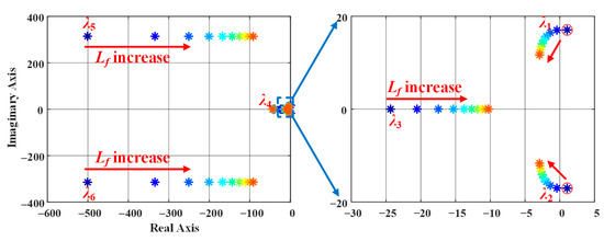
Figure 8.
Eigenvalue map when Lf changes from 1 mH to 10 mH, where * denotes eigenvalues.
The influence of the current gain (Ki) is depicted in Figure 9, where Ki varies from 0.5 Ki,set to 2 Ki,set and Ki,set = 83.82 is the designed value (from Table 3). The dominant eigenvalues demonstrate that increasing Ki enhances the system’s response speed but reduces ξ, leading to faster yet more oscillatory behaviour (i.e., higher OS).
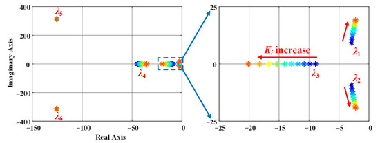
Figure 9.
Eigenvalue map when Ki changes from 0.5Ki,set to 2Ki,set, where * denotes eigenvalues.
Finally, Figure 10 shows the eigenvalue variation as μ changes from 0.5μset to 2μset, where μset = 2.38 × 10⁻⁴ is the designed value. The dominant eigenvalues (λ1,2) remain nearly constant, implying minimal impact on the transient response. However, λ3 moves further left with increasing μ, reducing its dominance in system dynamics, while λ4 initially shifts left and then changes slightly. These observations indicate that μ mainly affects non-dominant modes with a negligible influence on overall transient performance.
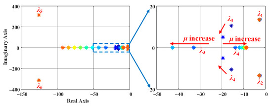
Figure 10.
Eigenvalue map when μ changes from 0.5μset to 2μset, where * denotes eigenvalues.
4. Experimental Validation
To validate the theoretical findings, the AHO-based strategies are experimentally implemented as shown in Figure 11, using the parameters listed in Table 3. The Cinergia 7.5 kVA grid emulator is employed to simulate the grid behaviour, while the control algorithm is implemented on a dSPACE DS1007 real-time system.
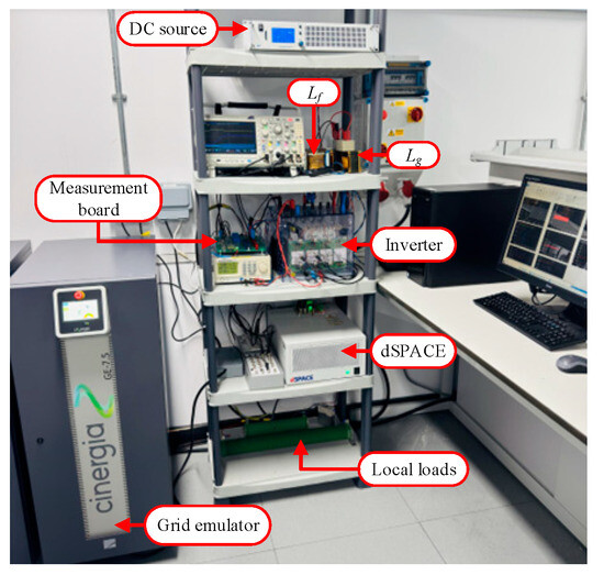
Figure 11.
Experimental test setup.
For simplicity, the DC side of the converter is modelled as a stiff voltage source, representing the short-term behaviour of EV’s onboard battery [2]. In practical applications, however, the battery’s state of charge (SoC) must be continuously monitored, and the provision of ancillary services should be coordinated with charging requirements. Similarly, operation in islanded mode must respect the allowable battery discharge limits and, in some cases, be coordinated with other distributed generation sources within the microgrid [2]. Since these supervisory functions typically operate on much slower timescales than the fast inner control loops considered in this study, they can be implemented within a higher-level hierarchical control layer for power and energy management, similar to the frameworks described in [39]. Therefore, such energy management aspects are beyond the scope of this paper and are not discussed further.
In the following, theoretical findings are validated through three test scenarios.
4.1. Test Scenario 1: Providing V2G Service
In this test, the active power support capability of the VI-AHO and Da-AHO, two of the most recent and successful VOC-based inverter strategies, is evaluated under a grid frequency disturbance. Both inverters operate with Pref = 500 W, delivering energy from the DC source to the grid. Subsequently, the grid frequency is reduced from 50 Hz to 49.7 Hz. As a GFM controller, both methods are expected to increase their output power in response to the frequency drop due to their embedded droop characteristics, thereby exhibiting V2G functionality.
Figure 12 presents the results, where Δf = f − 50 denotes the frequency deviation. Both control strategies successfully deliver an additional 1100 W of active power in response to the frequency reduction. However, as shown in Figure 12a, the VI-AHO exhibits significant oscillations with approximately 70% of power OS due to the absence of explicit damping enhancement. In contrast, the Da-AHO in Figure 12b demonstrates a well-damped response with negligible oscillations.
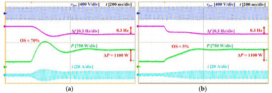
Figure 12.
Experimental results of Test Scenario 1: (a) VI-AHO and (b) Da-AHO.
4.2. Test Scenario 2: Providing V2H Service
This scenario evaluates the performance of VI-AHO and Da-AHO in stand-alone operation, representing V2H functionality. Initially, the inverters supply a 480 W resistive load (100 Ω). Subsequently, an additional 33 Ω load is connected in parallel, increasing the total load demand.
The experimental results in Figure 13 show that both controllers maintain stable operation in islanded mode, effectively supporting V2H operation during grid outages. Furthermore, both strategies achieve smooth frequency transitions with acceptable RoCoF following the load variation. This behaviour demonstrates the beneficial inertial response provided by both oscillators.
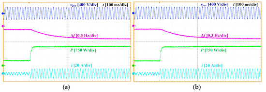
Figure 13.
Experimental results of Test Scenario 2: (a) VI-AHO and (b) Da-AHO.
4.3. Test Scenario 3: Validation of Small-Signal Analysis
In this scenario, the small-signal predictions from the state-space analysis in Section 3 are validated through experimental testing. To do so, the reference power Pref is jumped from 500 W to 2000 W under different parameter settings to investigate their influence on the transient response.
Figure 14 illustrates the results for the baseline case with the parameters listed in Table 3. The inverter output power tracks its reference with a 43% OS and a trise of 130 ms, closely matching the 53% OS and 131 ms trise predicted from the dominant eigenvalues in Table 4. The slight reduction in measured OS is attributed to damping introduced by parasitic resistances.
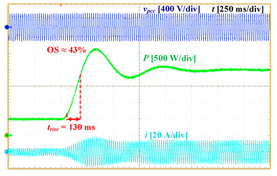
Figure 14.
Experimental results of Test Scenario 3: Baseline case.
Figure 15a shows the response when Tf decreases to 1/(6π) s, resulting in a faster and less oscillatory transient compared to the baseline Tf = 1/(2π) s case in Figure 14. This observation is consistent with the eigenvalue map in Figure 5, where smaller Tf increases both ξ and ꞷn.
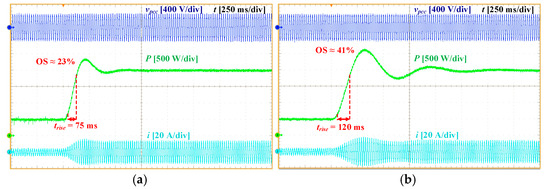
Figure 15.
Experimental results of Test Scenario 3: (a) Tf = 1/(6π) s and (b) Rg = 0.1 Ω.
The effect of grid resistance is illustrated in Figure 15b for Rg = 0.1 Ω. The step response shows only minor variations compared to the baseline case (Rg = 1 Ω in Figure 14), consistent with Figure 6, where changes in Rg had minimal influence on the dominant eigenvalues.
Figure 16a,b shows the results for Lg = 10 mH and Lf = 10 mH, respectively. In both cases, the response becomes slower with a lower OS compared to the baseline (Lg = 1 mH and Lf = 7 mH). These results align with Figure 7 and Figure 8, where increasing Lg and Lf enhanced damping of the dominant modes and shifted non-dominant eigenvalues closer to the imaginary axis.
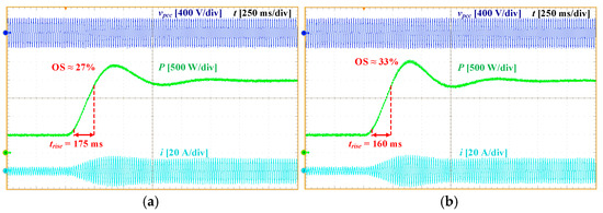
Figure 16.
Experimental results of Test Scenario 3: (a) Lg = 10 mH and (b) Lf = 10 mH.
The influence of control parameters is demonstrated in Figure 17. When Ki is doubled (Ki = 2Ki,set), the response becomes significantly faster (85 ms of trsie) but more oscillatory, with 60% OS. This agrees with Figure 9, where increasing Ki led to faster yet less damped dynamics. Conversely, when μ is doubled (μ = 2μset), Figure 17b shows almost identical behaviour to the baseline, confirming the small-signal result from Figure 10 that variations in μ had minimal impact on the dominant eigenvalues.
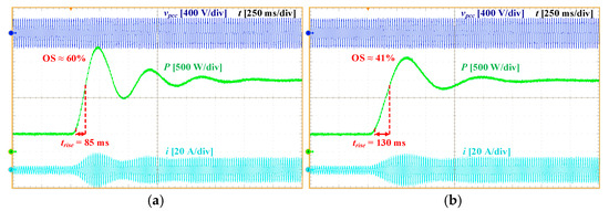
Figure 17.
Experimental results of Test Scenario 3: (a) Ki = 2Ki,set and (b) μ = 2μset.
Table 5 compares the measured OS and trise from the experiments with those calculated from the dominant eigenvalues in Section 3. For the calculation, the system is approximated as a second-order system. The measured results show strong agreement with the theoretical predictions, validating the accuracy of the state-space model. The experimental OS is approximately 10% lower, mainly due to parasitic damping, while the small difference in trise is mainly attributed to the effect of the neglected non-dominant eigenvalues.
Table 5.
Comparison between theoretical and experimental results.
5. Conclusions
This paper presented a comprehensive investigation of VOC strategies for GFM inverters, with particular emphasis on the AHO and its recent advancements. A comparative review demonstrated that although all VOC structures inherently provide droop functionality, AHO-based approaches offer superior ancillary services, including dispatchability, FRT capability, and the integration of virtual inertia and damping. Nevertheless, a unified control framework that simultaneously provides all these services has yet to be developed.
A generalised small-signal state-space model was developed to evaluate the dynamic performance of recent AHO-based inverters. Eigenvalue analysis revealed that virtual inertia enhances frequency stability at the cost of slower and more oscillatory dynamics, whereas increasing grid or filter inductance improves damping but reduces response speed. Experimental validation using a 2.5 kVA prototype confirmed the theoretical predictions, demonstrating close agreement between measured and calculated transient parameters. The results further demonstrated that damping-enhanced AHO strategies effectively balance stability and transient performance, providing a robust framework for future GFM control in EV-based and renewable-rich power systems.
Despite these advancements, further research is needed to accelerate the practical adoption of VOC-based inverters. In particular, there is a need for a unified control framework capable of delivering multiple ancillary services simultaneously. Future work will also address potential challenges in large-signal conditions and synchronisation performance to evaluate system stability under severe grid disturbances. Additionally, implementing VOC strategies in multi-inverter systems presents further research opportunities.
Author Contributions
Conceptualization, H.R., M.M., M.F. and S.G.; Methodology, H.R., M.M. and S.G.; Validation, H.R., M.M., M.F. and S.G.; Formal analysis, H.R., M.M., M.F. and S.G.; Investigation, H.R., M.M., M.F. and S.G.; Resources, M.M.; Writing—original draft, H.R., M.M., M.F. and S.G.; Writing—review & editing, H.R., M.M., M.F. and S.G.; Visualization, H.R., M.M., M.F. and S.G.; Supervision, M.M., M.F. and S.G.; Project administration, M.M. and M.F. All authors have read and agreed to the published version of the manuscript.
Funding
This research received no external funding.
Data Availability Statement
The original contributions presented in this study are included in the article. Further inquiries can be directed to the corresponding author.
Conflicts of Interest
The authors declare no conflict of interest.
References
- Muftau, B.; Fazeli, M. The Role of Virtual Synchronous Machines in Future Power Systems: A Review and Future Trends. Electr. Power Syst. Res. 2022, 206, 107775. [Google Scholar] [CrossRef]
- Suul, J.A.; DArco, S.; Guidi, G. Virtual Synchronous Machine-Based Control of a Single-Phase Bi-Directional Battery Charger for Providing Vehicle-to-Grid Services. IEEE Trans. Ind. Appl. 2016, 52, 3234–3244. [Google Scholar] [CrossRef]
- Rosas, D.S.Y.; Zarate, A. Single-Phase Grid-Forming Strategy with Power Decoupling Implementation for Electrolytic-Capacitor-Free EV Smart Battery Charger. Energies 2023, 16, 894. [Google Scholar] [CrossRef]
- Johnson, B.B.; Dhople, S.V.; Hamadeh, A.O.; Krein, P.T. Synchronization of parallel single-phase inverters with virtual oscillator control. IEEE Trans. Power Electron. 2014, 29, 6124–6138. [Google Scholar] [CrossRef]
- Johnson, B.B.; Sinha, M.; Ainsworth, N.G.; Dorfler, F.; Dhople, S.V. Synthesizing Virtual Oscillators to Control Islanded Inverters. IEEE Trans. Power Electron. 2016, 31, 6002–6015. [Google Scholar] [CrossRef]
- Lu, M.; Dutta, S.; Purba, V.; Dhople, S.; Johnson, B. A Grid-compatible Virtual Oscillator Controller: Analysis and Design. In Proceedings of the 2019 IEEE Energy Conversion Congress and Exposition (ECCE), Baltimore, MD, USA, 29 September–3 October 2019; pp. 2643–2649. [Google Scholar] [CrossRef]
- Lu, M. Virtual Oscillator Grid-Forming Inverters: State of the Art, Modeling, and Stability. IEEE Trans. Power Electron. 2022, 37, 11579–11591. [Google Scholar] [CrossRef]
- Awal, M.A.; Husain, I. Unified Virtual Oscillator Control for Grid-Forming and Grid-Following Converters. IEEE J. Emerg. Sel. Top. Power Electron. 2021, 9, 4573–4586. [Google Scholar] [CrossRef]
- Rezazadeh, H.; Monfared, M.; Fazeli, M.; Golestan, S. Providing Inertial Response with Unified VOC for Single-phase GFM Inverters. In Proceedings of the 2024 International Symposium on Electrical, Electronics and Information Engineering (ISEEIE), Leicester, UK, 26–28 September 2024; pp. 94–98. [Google Scholar] [CrossRef]
- Luo, S.; Chen, W.; Li, X.; Hao, Z. A New Virtual Inertial Strategy for Andronov–Hopf Oscillator Based Grid-Forming Inverters. IEEE J. Emerg. Sel. Top. Power Electron. 2024, 12, 1995–2005. [Google Scholar] [CrossRef]
- Rezazadeh, H.; Monfared, M.; Fazeli, M.; Golestan, S. Enhancing Damping in Single-Phase Grid-Forming Virtual Oscillator Control Inverters: A Feedforward Strategy. IEEE Open J. Ind. Electron. Soc. 2025, 6, 1101–1115. [Google Scholar] [CrossRef]
- Rezazadeh, H.; Monfared, M.; Fazeli, M.; Golestan, S. Voltage-Independent Active-Power Droop Coefficient for Enhanced Andronov–Hopf Oscillator Grid-Forming Inverters. arXiv 2025, arXiv:2511.05252. [Google Scholar]
- Aghdam, S.A.; Agamy, M. Virtual oscillator-based methods for grid-forming inverter control: A review. IET Renew. Power Gener. 2022, 16, 835–855. [Google Scholar] [CrossRef]
- Lu, M.; Dhople, S.; Johnson, B. Benchmarking Nonlinear Oscillators for Grid-Forming Inverter Control. IEEE Trans. Power Electron. 2022, 37, 10250–10266. [Google Scholar] [CrossRef]
- Rezazadeh, H.; Monfared, M.; Fazeli, M.; Golestan, S. Single-phase Grid-forming Inverters: A Review. In Proceedings of the 2023 International Conference on Computing, Electronics & Communications Engineering (iCCECE), Swansea, UK, 14–16 August 2023; pp. 7–10. [Google Scholar] [CrossRef]
- Lu, M.; Purba, V.; Dhople, S.; Johnson, B. Comparison of Droop Control and Virtual Oscillator Control Realized by Andronov-Hopf Dynamics. IECON Proc. (Ind. Electron. Conf.) 2020, 2020, 4051–4056. [Google Scholar] [CrossRef]
- Rezazadeh, H.; Monfared, M.; Fazeli, M.; Golestan, S. Virtual Oscillator Control for Grid-forming Inverters: An Overview of Recent Developments and Small-Signal Analysis. ECCE 2025, in press.
- Johnson, B.B.; Dhople, S.V.; Cale, J.L.; Hamadeh, A.O.; Krein, P.T. Oscillator-Based Inverter Control for Islanded Three-Phase Microgrids. IEEE J. Photovolt. 2014, 4, 387–395. [Google Scholar] [CrossRef]
- Leyba, E.R.M.; Opila, D.F.; Kintzley, C.K. Three Phase Dead-Zone Oscillator Control Under Unbalanced Load Conditions. In Proceedings of the 2019 IEEE Electric Ship Technologies Symposium (ESTS), Washington, DC, USA, 14–16 August 2019; pp. 134–140. [Google Scholar] [CrossRef]
- Sinha, M.; Dhople, S.; Johnson, B.; Ainsworth, N.; Dorfler, F. Nonlinear supersets to droop control. In Proceedings of the 2015 IEEE 16th Workshop on Control and Modeling for Power Electronics (COMPEL), Vancouver, BC, Canada, 12–15 July 2015; pp. 1–6. [Google Scholar] [CrossRef]
- Raisz, D.; Thai, T.T.; Monti, A. Power Control of Virtual Oscillator Controlled Inverters in Grid-Connected Mode. IEEE Trans. Power Electron. 2019, 34, 5916–5926. [Google Scholar] [CrossRef]
- Awal, M.A.; Yu, H.; Tu, H.; Lukic, S.M.; Husain, I. Hierarchical Control for Virtual Oscillator Based Grid-Connected and Islanded Microgrids. IEEE Trans. Power Electron. 2020, 35, 988–1001. [Google Scholar] [CrossRef]
- Awal, M.A.; Yu, H.; Husain, I.; Yu, W.; Lukic, S.M. Selective Harmonic Current Rejection for Virtual Oscillator Controlled Grid-Forming Voltage Source Converters. IEEE Trans Power Electron. 2020, 35, 8805–8818. [Google Scholar] [CrossRef]
- Awal, M.A.; Rachi, M.R.K.; Yu, H.; Husain, I.; Lukic, S. Double Synchronous Unified Virtual Oscillator Control for Asymmetrical Fault Ride-Through in Grid-Forming Voltage Source Converters. IEEE Trans. Power Electron. 2023, 38, 6759–6763. [Google Scholar] [CrossRef]
- Costa, D.A.; Tôrres, L.A.B.; Silva, S.M.; De Conti, A.; Brandão, D.I. Parameter Selection for the Virtual Oscillator Control Applied to Microgrids. Energies 2021, 14, 1818. [Google Scholar] [CrossRef]
- Shi, Z.; Li, J.; Nurdin, H.I.; Fletcher, J.E. Comparison of Virtual Oscillator and Droop Controlled Islanded Three-Phase Microgrids. IEEE Trans. Energy Convers. 2019, 34, 1769–1780. [Google Scholar] [CrossRef]
- Li, J.; Fletcher, J.E.; Holmes, D.G.; McGrath, B.P. Developing a machine equivalent inertial response for a Virtual Oscillator Controlled Inverter in a machine-inverter based microgrid. In Proceedings of the 2020 IEEE Energy Conversion Congress and Exposition (ECCE), Detroit, MI, USA, 11–15 October 2020; pp. 4314–4321. [Google Scholar] [CrossRef]
- Aghdam, S.A.; Agamy, M. Adaptive Virtual Inertia Synthesis via Enhanced Dispatchable Virtual Oscillator Controlled Grid-Tied Inverters. In Proceedings of the IECON 2021—47th Annual Conference of the IEEE Industrial Electronics Society, Toronto, ON, Canada, 13–16 October 2021; pp. 1–6. [Google Scholar] [CrossRef]
- Inverters, G. A Nonlinear MPC-Based Adaptive Inertia Strategy for Andronov-Hopf Oscillator Controlled. In Proceedings of the IEEE Energy Conversion Congress and Exposition, Phoenix, AZ, USA, 20–24 October 2024; pp. 1506–1511. [Google Scholar] [CrossRef]
- Awal, M.A.; Husain, I. Transient Stability Assessment for Current-Constrained and Current-Unconstrained Fault Ride through in Virtual Oscillator-Controlled Converters. IEEE J. Emerg. Sel. Top. Power Electron. 2021, 9, 6935–6946. [Google Scholar] [CrossRef]
- Yu, H.; Awal, M.A.; Tu, H.; Husain, I.; Lukic, S. Comparative Transient Stability Assessment of Droop and Dispatchable Virtual Oscillator Controlled Grid-Connected Inverters. IEEE Trans. Power Electron. 2021, 36, 2119–2130. [Google Scholar] [CrossRef]
- Luo, S.; Chen, W.; Hao, Z.; Wang, Y. A Transient Stability Enhanced Andronov-Hopf Oscillator for Grid-Forming Converters. IEEE Trans. Power Electron. 2024, 39, 10853–10864. [Google Scholar] [CrossRef]
- Li, L.; Song, H.; Wang, S.; Liu, M.; Gao, S.; Li, H. Transient Stability Analysis and Enhanced Control Strategy for Andronov-Hopf Oscillator Based Inverters. IEEE Trans. Energy Convers. 2025, 40, 995–1008. [Google Scholar] [CrossRef]
- Lu, M. An Inrush Current Limiting Strategy for Virtual-Oscillator-Controlled Grid-Forming Inverters. IEEE Trans. Energy Convers. 2023, 38, 1501–1510. [Google Scholar] [CrossRef]
- Gurugubelli, V.; Ghosh, A.; Panda, A.K. Improved Hopf Oscillator-Based VOC Method for Fast Synchronization of Parallel Inverters in Standalone Microgrid. IEEE J. Emerg. Sel. Top. Power Electron. 2024, 12, 3018–3025. [Google Scholar] [CrossRef]
- Tran, T.T.; Gurumurthy, S.K.; Tran, M.-Q.; Nguyen-Huu, T.-A.; Heins, T.; Ponci, F.; Monti, A.; Nguyen, P.H. Enhancing Performance of Andronov-Hopf Oscillator-Based Grid-Forming Converters in Microgrids with Non-Invasive Online Impedance Estimation. IEEE Trans. Smart Grid 2023, 14, 4479–4493. [Google Scholar] [CrossRef]
- Zeng, Z.; Fan, J.; Sun, Y.; Wang, S.; Yang, D. A Dispatchable Virtual Oscillator Controller in the dq Frame with Enhanced Grid-Forming Power Reference Tracking Capability. IEEE Trans. Power Electron. 2025, 40, 10973–10987. [Google Scholar] [CrossRef]
- Task Force C6.04.02. In Benchmark Systems for Network Integration of Renewable and Distributed Energy Resources; Brochure No. 575; CIGRE: Paris, France, 2014; ISBN 978-2-85873-270-8.
- Guerrero, J.M.; Vasquez, J.C.; Matas, J.; de Vicuna, L.G.; Castilla, M. Hierarchical Control of Droop-Controlled AC and DC Microgrids—A General Approach Toward Standardization. IEEE Trans. Ind. Electron. 2011, 58, 158–172. [Google Scholar] [CrossRef]
Disclaimer/Publisher’s Note: The statements, opinions and data contained in all publications are solely those of the individual author(s) and contributor(s) and not of MDPI and/or the editor(s). MDPI and/or the editor(s) disclaim responsibility for any injury to people or property resulting from any ideas, methods, instructions or products referred to in the content. |
© 2025 by the authors. Licensee MDPI, Basel, Switzerland. This article is an open access article distributed under the terms and conditions of the Creative Commons Attribution (CC BY) license (https://creativecommons.org/licenses/by/4.0/).