Abstract
This study investigates a Solar Air Heating Façade (SAHF), architecturally enhanced through the integration of granular translucent Silica-Aerogel into multi-wall polycarbonate (PC) panels and the implementation of coated timber lamellas. The novelty of this work lies in the combined evaluation of thermal resistance and solar transmission properties of façade-integrated components, aiming to improve both energy efficiency and architectural integration. Two experimental campaigns were conducted: (i) thermal transmittance tests to determine the U-value of PC panels with and without Silica-Aerogel infill, and (ii) solar transmission measurements under controlled artificial solar radiation to evaluate the optical performance of various lamella configurations and coatings. Results show that the incorporation of Silica-Aerogel reduced the U-value by 41.8%, achieving a minimum of 1.19 W/m2 K with the 20 mm thick PC panel, while decreasing the solar transmission of 43–53% depending on the incidence angle. The integration of reflective aluminum-coated timber lamella demonstrated promising results, enabling effective management of solar radiation. These findings highlight the potential of façade systems that combine high-performance insulation with visually integrated shading elements.
1. Introduction
Energy consumption has driven the development and adoption of sustainable technologies for various practical applications. Today, the building sector accounts for approximately 40% of the total global energy consumption, thus making it a critical area for improvement [1]. The integration of solar energy systems into buildings is one of the most promising solutions that has been developed. These systems play an increasingly important role in reducing energy demand by producing renewable energy and enhancing energy efficiency [2]. The Trombe wall, which consists of an outer glazed layer, an air gap, and a thermally massive inner wall with two vents positioned at the top and bottom, is a well-known example of passive solar systems [3]. This system, when included as part of a Solar Air Heating Façade (SAHF), functions as a passive mechanism for both heating and cooling. A Trombe wall, which harnesses solar radiation and ambient temperature variations, stores energy and releases it into the indoor environment at optimal times and rates. Since architectural integration is one of the most relevant market barriers to this kind of system, this study has explored different strategies to enhance the architectural integration of Trombe wall-based SAHF, while simultaneously improving their thermal performance. One of the most effective ways of minimizing heat losses in buildings is to enhance the thermal resistance of the envelope using either opaque or transparent insulation materials. Therefore, the first strategy we considered, which involved filling the gap with translucent material, was aimed at increasing the thermal resistance of the glazed element to enhance its insulating properties. This approach significantly reduces the energy required to maintain indoor thermal comfort [4,5]. Several well-established solutions exist for transparent elements, including double glazing with inert gas, where argon or krypton is used between two glass panes to reduce heat [6]. Triple glazing with low-emissivity (Low-E) coatings, which is used to obtain improved insulation, involves adding a third pane with a special coating that reflects infrared radiation, while allowing visible light to pass through. Selective-tint, double glazing further controls solar heat gains, due to the use of tinted glass, whereby a balance is achieved between thermal insulation and daylighting. Polycarbonate (PC), multiwall panels have also gained popularity in building applications, because of their lightweight nature, durability, and their resistance to fire, weather, and UV radiation. These panels are versatile and can be used in fenestration systems, continuous windows, skylights, roofs, and walls, and they offer a variety of cell geometries, colours, and thicknesses. In addition to being more cost-effective than traditional glazing, PC panels can significantly improve the thermal performance of a building, if they have been properly designed, and they can result in substantial energy savings, particularly for commercial and industrial buildings [7]. Recent research into façade systems has involved investigating both silica-aerogel-based insulation and reflective coatings to enhance thermal performances. Buratti and Moretti [7] investigated the integration of a granular silica-aerogel into polycarbonate (PC) multiwall panels of various thicknesses (16, 25, and 40 mm) to enhance the thermal performance of non-residential buildings. Experimental and numerical analyses have revealed that aerogel-filled PC panels can achieve a reduction of 46–68% of the U-values, compared to air-filled systems, with values ranging from 1.4 W/m2 K for 16 mm panels to 0.6 W/m2 K for 40 mm panels. Although light transmittance decreases as the thickness increases, the reduction is acceptable for 16 mm panels, but it is even more significant for 40 mm panels. Another advanced solution is the use of silica-aerogel, a highly insulating, translucent material that can be incorporated into glazing systems to further reduce heat losses [8]. It in fact offers high thermal resistance, but it also requires significantly thinner layers than traditional insulation materials, and it enables a reduction in the overall thickness of a building structure. Silica-Aerogel is an ultra-lightweight, nanostructured porous material that has a three-dimensional network. Its skeletal density is approximately 2200 kg/m3 [9]. Because of its high porosity (it has pores ranging from 5 to 100 nm, which occupy over 90% of the total volume), the bulk density typically falls between 80 and 200 kg/m3 [10], although, in some cases, it can be as low as 3 kg/m3 [11]. This material boasts an exceptionally high specific surface area, which can reach up to 1000 m2/g [12]. Silica-aerogel, known to be one of the lightest and most effective insulating solid materials, exhibits a remarkably low thermal conductivity, that is, as low as 0.013 W/(m·K). This low conductivity is achieved through a combination of reduced solid and gaseous thermal conductivity, along with minimal infrared radiation transmission [13]. The most notable advantage of silica-aerogel is that it can function as an optical filter, as it is opaque to infrared radiation but remains transparent to sunlight. The spectral and physical properties of silica-Aerogel make it highly effective in suppressing heat losses. Additionally, silica-aerogel is characterized by its non-toxicity, durability, low flammability, lightweight nature, and air permeability. Transparent silica-aerogel has recently garnered significant attention from researchers due to its exceptional insulation capabilities. It effectively prevents heat losses while allowing high solar transmission, a performance feature that has been attributed to its transparency to sunlight, opacity to infrared radiation, and extremely low thermal conductivity.
Architectural integration poses significant challenges, because it requires the balancing of technical functionality with aesthetic considerations. Indeed, integrating SAHF systems into building façades often involves trade-offs between maintaining structural integrity and achieving a visually appealing design. Additionally, there are certain material and technical constraints, such as the use of coatings and configurations that provide both high thermal efficiency and a seamless integration with diverse architectural styles. Overcoming these challenges necessitates innovative strategies that can harmonize energy efficiency with design flexibility. Therefore, the second strategy we adopted involved applying wooden lamellas with improved solar reflectance properties.
The use of lamellas as a shading device in solar façades provides both solar regulation and enhanced architectural aesthetics. Their lightweight structure, ease of installation, and natural visual appeal make them attractive design elements. When integrated into SAHF systems, lamellas introduce innovative ways of merging architecture with passive heating and cooling systems. Trombe walls, which are traditionally black to obtain an optimal heat absorption, often lack aesthetic appeal, and this can limit their market adoption. However, to address this issue, architects can explore a variety of design strategies, such as incorporating lamellas to add depth and texture, selecting advanced coatings to modify the appearance without compromising efficiency, and/or integrating materials that blend with the overall aesthetics of a building. A thoughtful orientation and choice of the materials and of the spacing of the lamella will ensure not only an improved energy performance but also durability, airflow regulation, and seamless architectural integration, which, in turn, will make SAHF systems more appealing and adaptable to diverse architectural styles.
However, to enhance their thermal performance, these lamellas require advanced surface modifications to improve their solar reflectance, mitigate overheating, and optimize the use of solar energy. Coatings or surface treatments are important to increase the ability of lamellas to reflect incident solar radiation. These coatings, which are an important innovation in building materials, offer such benefits as better energy efficiency, sustainability, improved thermal comfort, and support in managing urban microclimates [14]. Reflective materials make use of a wide range of substances that utilize the principle of reflection for various applications across industries. Spectrally selective (SS) materials, retroreflective (RR) materials, thermochromic materials, and other specialized reflective substances are some of the most frequently used materials. As far as the coupling of silica aerogel and solar management is concerned, Zhao et al. [15] developed a system that achieved temperatures above 473 K under real-world, weather conditions, without relying on an optical concentrator, by integrating silica-aerogel with a flat-plate solar receiver.
Qiu et al. [16] designed an innovative parabolic trough receiver insulated with silica-aerogel, which demonstrated an efficiency improvement of 0.32–5.04%. Zhao et al. [17] achieved a silica-aerogel with an exceptionally high solar transmittance (95%) by optimizing its microstructure to minimize scattering. Building on this advancement and utilizing aerogel, they developed a solar thermal device that could generate steam at 100 °C, and which had an efficiency of 56% under a solar irradiation of 700 W/m2. Lv et al. [18] examined the performance of 12 aerogel-filled glazing samples, with different average particle sizes and filling thicknesses, using a spectrophotometer. Although aerogels are commonly utilized in solar thermal absorbers, their potential applications in solar systems are still an area of ongoing exploration to address existing knowledge gaps. Furthermore, many studies have investigated various alternative reflective materials. W. Guo et al. [19] investigated the energy-saving effects of a heat-reflective, insulating coating on exterior walls in Hangzhou, China. They conducted experimental tests in test rooms with and without the coating, and they found that the coating reduced the exterior wall surface temperatures by 8–10 °C, which resulted in an annual reduction of approximately 5.8 kWh/m2 per month in the electricity consumption for air-conditioning. R. Levinson et al. [20] developed methods to create non-white, solar-reflective surfaces by combining NIR-scattering pigments with reflective basecoats. These materials led to an enhancement of the reflectance of such roofing materials as metal, clay tiles, concrete, wood, and asphalt shingles.
A. Charikleia et al. [21] evaluated the impact of advanced coatings on building façades, considering their thermal and optical properties, such as low thermal conductivity, high solar reflectance, and high emissivity. Their results revealed that the cooling loads in Athens, Greece, reduced by as much as 48.4%, and they reduced by 76.2% in Warsaw, Poland, while the heating loads decreased by 17.2% and 11.8%, respectively. S. Malz et al. [22] explored the use of infrared, reflective, wall paint combined with heat insulation for historic brick masonry. Their results demonstrated that energy savings of 18% to 22% could be achieved under thermal comfort conditions.
Spoke 4 “Digital and Sustainable Mountains”, Research Module Interface [23], in the framework of the NODES project, is aimed at developing novel envelope solutions that are suitable for both the energy retrofitting of existing buildings and for new buildings in mountainous areas. This study is aimed at enhancing the architectural integration of (SAHF) systems, while maintaining their thermal and solar performances (Figure 1). Two strategies have been explored: (1) the use of a silica-aerogel infill in polycarbonate panels to increase thermal resistance, and (2) the application of coated lamellas to control solar transmission and improve visual integration. The experimental analysis involved evaluating various material configurations and lamella geometries under controlled conditions to assess their effectiveness in optimizing their energy performance and the façade aesthetics. The present research, by combining advanced insulation materials with reflective shading elements, proposes integrated solutions as a response to modern architectural demands, and it aims to contribute toward providing energy-efficient and climatically responsive building envelopes.
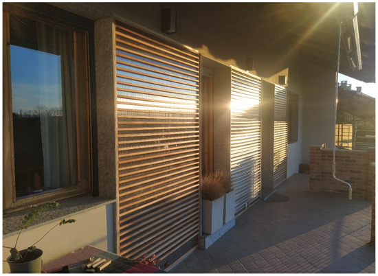
Figure 1.
Photograph of full-scale demonstrator of architecturally integrated solar façades developed within the framework of the NODES project.
2. Methodology
This study has focused on assessing the energy performance of an SAHF system through an experimental investigation of its main sub-components. Two key elements were examined: polycarbonate panels filled with silica aerogel to obtain enhanced thermal insulation, and timber lamellas coated with white paint and reflective aluminium for solar radiation control purposes. A dedicated experimental setup was developed to evaluate the thermal transmittance (U-value) and solar transmission of these façade configurations. Thermal transmittance measurements were performed using a Heat Flow Meter (HFM), in accordance with standardized procedures. An artificial sun was employed within a climatic chamber (BET-cell) to simulate solar radiation, while consistent irradiance and ambient conditions were ensured. The lamella configurations, which were designed to be integrated into large-scale Trombe wall systems, consisted of lightweight horizontal elements optimized to enhance their thermal performance, while preserving structural stability and visual quality.
2.1. Heat Balance of the External Glazed Element
The interactions between reflection, absorption, and transmission within the SAHF are illustrated in Figure 2. When solar radiation reaches the glazed element, it is partly transmitted into the cavity and partly reflected toward the exterior environment. First, a part of this absorbed energy is re-emitted as long-wave infrared radiation from the inner surfaces of the glazed element. In addition, a considerable portion of the absorbed heat is transferred to the air by means of natural convection, thereby increasing the air temperature within the cavity and promoting a buoyancy-driven flow. This heated air creates a thermal gradient that cause continuous circulation inside the channel. Furthermore, the stored heat is also conducted toward the massive wall, thereby contributing to the overall heat balance. This conductive transfer, combined with convective and radiative exchanges, defines the net heat gain that was available to be transferred to the indoor space.
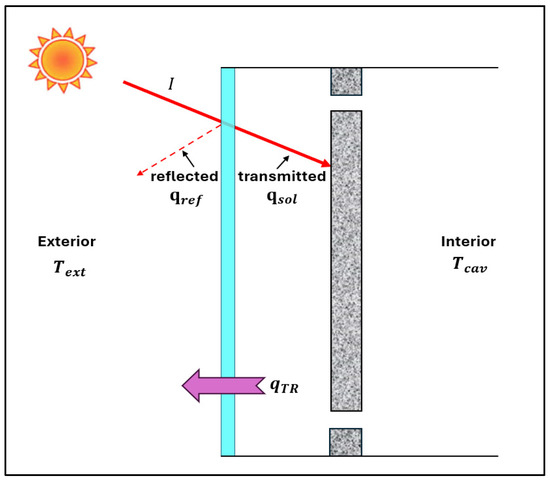
Figure 2.
Heat balance of the external glazed element.
The primary objective of this configuration was to maximize the solar gains that entered the cavity of the SAHF system. When solar radiation reached the surface of the lamellas, the material properties of the coating were responsible for how the radiation was transmitted. A part of the incident solar radiation was reflected by the coated lamella surface toward the polycarbonate panel. This controlled reflection effectively redirected a portion of the solar energy that would otherwise have been lost, and it thus enhanced the solar irradiation received by the polycarbonate layer. The polycarbonate panel, in turn, transmitted a portion of this redirected radiation into the cavity. Therefore, the use of reflective top coatings, in this context, reduced the rejected solar radiation, as is typical in passive cooling strategies, and redirected and concentrated the solar energy toward the transparent façade surface, thereby improving the solar collection efficiency. This approach supported the thermal performance of the SAHF system by amplifying the movement of direct and reflected solar gains into the cavity.
A comprehensive heat balance analysis is essential to understand the energy transfer processes that occurred in the system, including the solar gains and the heat losses to the ambient environment.
Mathematically, the total heat flux Qnet that entered the cavity space was governed by the following relationship (1):
Mathematically, the total heat flux Qnet entering the cavity space is governed by the following relationship (1):
where qsol is the heat flux that was transmitted into the interior due to solar radiation which is calculated by Equation (2) and qTR is the heat flux that was lost to the exterior which is calculated by Equation (3).
The transmitted solar heat flux qsol is defined as:
where g represents the solar heat gain coefficient or solar factor and I is the incident solar irradiance (W/m2).
The heat flux lost to the exterior is expressed as:
where U represents the convective and radiative heat transfer coefficient in the interior of the SAHF, Tcav is the SAHF cavity temperature (K) and Text is the exterior temperature (K).
The total heat flux Qnet, can be expressed under steady state conditions, according to Equation (4):
where qi represents the secondary heat flux that is absorbed and re-emitted.
Since it was not possible to determine the g-value of the translucent materials with low thermal conductivity due to the impossibility of shading a part of the surface of a heat flux meter sensor without locally perturbating the surface temperature the solar transmission (τ) component was used to estimate the heat balance, while the secondary flux absorbed and re-emitted into the SAHF was neglected in this analysis. This procedure can lead to an underestimation of the solar heat gains and can be only considered reliable only when the solar absorption part is marginal compared with the solar transmission part and for comparative purposes when considering different solutions.
2.2. Performance Metrics
This section presents the performance metrics and the experimental assessment methodology, focusing on the thermal performance and solar transmission characteristics of various configurations. The analysis was structured around three key performance indicators:
- The Thermal Transmittance (U)
The Thermal Transmittance was calculated in accordance with EN ISO 6946:2017 [24], following the simplified Formula (5):
The interior surface resistance (Rsi), equivalent to 0.13 (m2 K)/W and an exterior surface resistance (Rse), equivalent to 0,04 (m2 K)/W, were considered.
- The Solar Transmission factor (τ %)
The solar transmission factor τ which indicates the percentage of solar energy transmitted through the SAHF, was calculated as (6):
where Isample is the solar irradiation measured behind the sample and Iinc is the incident solar irradiation without sample.
- The Reduction Factor (RF%)
The Reduction Factor was used to measures how different configurations reduce the solar transmission in comparison with a reference baseline component, defined in Equation (7):
where τanalysed component is the solar transmission factor in the tested component and τbaseline is the solar transmission factor in the baseline component (PC without aerogel and without lamellas).
2.3. Analysed Samples
Four different multiwall polycarbonate panels were first tested and then employed to manufacture a small-scale prototype. The samples had to have a minimum measurable area of 300 × 300 mm to be tested with the HFM. Thus, 400 × 400 mm panels, with thicknesses of 20 mm, 16 mm and 10 mm, were fabricated to fulfil this requirement, (as shown in Figure 3a).
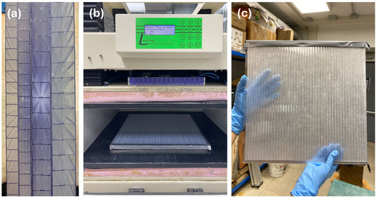
Figure 3.
(a) Details of the tested panels. From left to right: 20 mm thick panel with four cavities; 16 mm thick panel with 4 cavities; 10 mm thick panel with 4 cavities and 10 mm thick panel with 1 cavity; (b) Heat Flux Meter test setup; and (c) Hollow polycarbonate panel filled with Silica-aerogel.
The three panel thicknesses were selected to reproduce the typical U-values of Double-Glazing Units (DGUs), ranging from simple uncoated DGUs to argon-filled and Low-E coated systems. This allows the tested SAHF configurations to represent a realistic range of façade insulation levels, facilitating comparison with standard glazing technologies.
The prototype utilized for the solar transmission analysis consisted of a timber frame, which was used to hold the polycarbonate panels, as shown in Figure 4 and Figure 5. Additionally, the frame incorporated horizontal lamellas, and it enabled different coatings, widths, and orientations to be tested. The lamella box measured 40 × 40 cm, the lamella was positioned equidistantly, with an average spacing of 3.6 cm between them, and the overall assembly thickness was kept constant at 18 cm for all tested configurations. The polycarbonate panels were positioned behind the lamellas. Furthermore, the polycarbonate layer was tested under two different conditions: unfilled polycarbonate and silica-Aerogel filled polycarbonate to evaluate the impact of aerogel in the thermal insulation and solar transmission capabilities. Moreover, three different conditions of the top faces of the lamellas were considered to obtain three design options: wood on its own (uncoated), painted in white, and coated in reflective aluminium. In addition to the coatings, the influence of the lamella width was investigated using 2 cm and 3 cm configurations, as illustrated in Table 1, and they were evaluated in two orientations: a vertical baseline at 0° and inclined positions at 20° and 45°, to emulate the effect of different incident solar angles. Two pyranometers were placed behind the polycarbonate layer to measure the intensity of solar irradiation. At the same time, a data acquisition system recorded real-time solar transmission data.
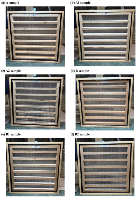
Figure 4.
Front views of the lamella configurations: (a) A—wood (3 cm); (b) A1—coated in white (3 cm); (c) A2—coated in aluminium (3 cm); (d) B—wood (2 cm); (e) B1—coated in white (2 cm); (f) B2—coated in aluminium (2 cm).
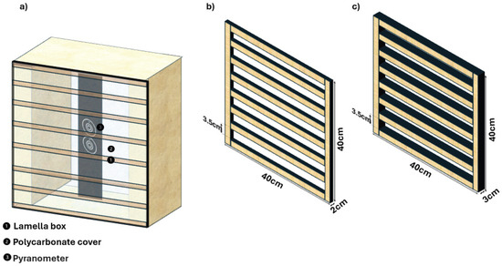
Figure 5.
Experimental setup components s: (a) Full setup with the lamella box, (b) Lamellas with (20–20) and (c) Lamellas with (20–30).

Table 1.
Material and dimensional specifications of Lamella samples.
2.4. Thermal Transmittance Measurements
The different alveolar polycarbonate samples with a multiple number of cavities and void fractions were tested in both an empty state (air cavities) and filled with aerogel. It should be mentioned that it was not possible to fill the 10 mm-thick panel (with four internal cavities) due to the limited size of the cavity; therefore, it was only tested in its empty configuration. The equivalent thermal conductivity with air cavities and the equivalent thermal conductivity with the aerogel infill were measured a Heat Flow Meter apparatus (LaserComp, Inc. © 2001-2005 Fox 600-20 Spring Street, Saugus, MA 01906, USA) illustrated in Figure 3b, according to ASTM C518 standard [25]. A granular CABOT aerogel (LUMIRA® Aerogel LA1000—Frankfurt, Germany) was employed, with a thermal conductivity of 0.017–0.022 W/mK, depending on the density.
The boundary conditions considered to perform the experiments and calculations are reported in Table 2. The repeatability of the test was proved by taking four different measures for each configuration of panels with both air cavities and aerogel infill. The test was performed twice with upwards flux direction and twice downwards. Laboratory room conditions were monitored by a Testo 175-H2 datalogger, resulting in an ambient temperature (Ta) of around 26 ± 1.5 °C and relative humidity (RH), around 34 ± 3.5%.
Table 2.
Heat Flow Meter temperature settings.
2.5. Solar Transmission Measurements
The prototype, which consisted of a lamella box and polycarbonate layer, as described in the previous section, was placed in front of the artificial sun solar radiation source during all the tests (Figure 6a). A fixed distance of 1 m was maintained between the light source and the prototype to ensure a uniform radiation intensity over the entire surface, thereby minimizing any potential irradiance gradients.
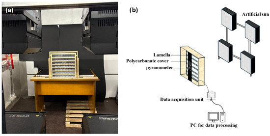
Figure 6.
(a) Experimental setup in BET-cell and (b) Schematic representation of the experimental setup for solar transmission analysis.
Three tilt angles (0°, 20°, and 45°) were selected to illustrate the effect of the angular positioning on solar transmission (Figure 7). These configurations were not intended to replicate specific real-world conditions but rather to provide a controlled framework in order to understand how different inclinations influenced the light modulation, irradiance distribution, and potential thermal gains. The study, by analysing different angles, aimed to highlight the impact of angular deviations on the performance of the system, and to offer insights into how tilt adjustments could affect energy efficiency.
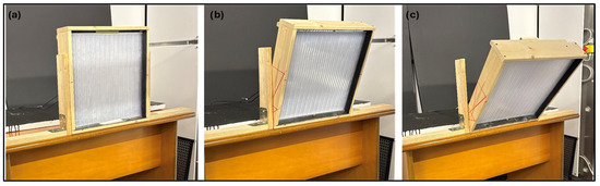
Figure 7.
Experimental set-up of the lamella box at three tilt angles: (a) 0°, (b) 20°, and (c) 45°.
The experimental set-up included an artificial sun, which was designed to replicate solar radiation under the standardized conditions shown in Figure 8a. The lighting system was made up of lamps with a correlated colour temperature (CCT) of 6500 K, in compliance with DIN 75220:1992 [26] and CEI EN IEC 60904-3:2020 [27], to ensure an accurate spectral distribution for solar simulation. These lamps were coupled with symmetric parabolic reflectors to produce a high proportion of parallel light beams to promote uniform irradiance over the test surface.
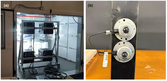
Figure 8.
(a) Artificial sun set-up and (b) Pyranometers.
The irradiated area measured at least 1200 mm × 1600 mm (height), and the irradiance intensity ranged from 1000 to 1200 W/m2 at its peak. The system was also dimmable to allow controlled adjustments of the irradiance to be made within a minimum range of 80–600 W/m2 and a maximum one of 600–1200 W/m2, depending on the test requirements.
The solar simulator satisfied the IEC 60904-9:2020 [28] classification requirements, that is, at least Class B for a spectral match (AM1.5 spectrum), Class C for non-uniformity (±10%), and Class A for temporal instability, thereby ensuring a short-term instability (STI) of ±0.5% and long-term instability (LTI) of ±2%. These parameters confirm the suitability of the simulator for accurate and repeatable thermal and optical performance evaluations of building components under controlled conditions.
Two second class Pyranometers (Hukseflux LP02 [29], as illustrated in Figure 8b) were installed behind the polycarbonate layer to monitor any localized variations of the irradiance intensity with an accuracy of ±5%.
The transmitted solar intensity was continuously recorded for each configuration, with data being sampled at a frequency of 10 s. Each test was conducted over a period of approximately 15 min to allow the system to reach thermal stability. However, only the data collected during the stabilized phase, that is, in the final 5 min, were considered for the analysis to ensure accurate and consistent results. The data recorded from this period were averaged to quantify the effective solar transmission for each tilt configuration. Additionally, spatial variations in the transmitted intensity were examined to evaluate the influence of the angular positioning on the uniformity and distribution of irradiance over the surface.
All the experiments were conducted under identical lighting and environmental conditions to isolate the effects of angular variation on solar transmission. All the inclination angle configurations were experimentally tested with the PC16 polycarbonate samples. Table 3 presents the measured global incident irradiance values and the corresponding transmitted irradiance for the different tested configurations.
Table 3.
Measured global incident and transmitted irradiance for different SAHF configurations (mean ± Standard Deviation).
The table reports the mean transmitted and incident solar irradiance values measured under stable artificial solar conditions for each configuration. The standard deviation (±SD) represents the repeatability of the measurements. The incident irradiance, monitored by a calibrated pyranometer, remained approximately constant at 982 ± 5 W/m2 during the tests.
3. Results and Discussion
3.1. Thermal Transmittance
Figure 9 illustrates the thermal transmittance (U-value) of the tested alveolar polycarbonate panels with air cavities and with an aerogel infill, along with the reference values provided by the manufacturer [30]. Each panel is labelled according to the thickness, followed by the number of cavities, e.g., the 20 mm panel with 4 cavities is “20 mm_4C”. The average U-values obtained from the laboratory HFM test confirms the values provided by the manufacturer. The U-value of the air-filled configurations increased as the panel thickness decreased. Standard Deviation (SD) was included in the plot whiskers to show the repeatability of the test, since all the measurements were done four different times, obtaining a SD of around 1% for all the different configurations.
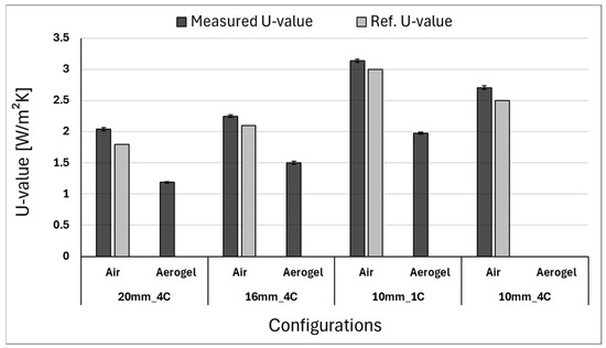
Figure 9.
Thermal transmittance (U-value) for all the alveolar polycarbonate panels with air cavities and aerogel infill. The reference U-value corresponds to the one provided by the company [30].
The 20 mm panel with four cavities exhibited a U-value of 2.03 W/m2 K, while the 16 mm panel with the same number of divisions recorded 2.25 W/m2 K. As expected, the 10 mm panel with one cavity presented the highest U-value of all the tested configurations and reached 3.09 W/m2 K. When aerogel was introduced as an infill, a substantial improvement in the thermal performance was observed for all the panels. The U-value of the 20 mm panel decreased from 2.03 W/m2 K (air) to 1.19 W/m2 K (aerogel), which corresponds to a reduction of 41.8%. Similarly, the 16 mm panel dropped from 2.25 W/m2 K to 1.51 W/m2 K (a reduction of 32.9%), while the 10 mm panel with two internal divisions showed a decrease from 3.09 W/m2 K to 1.97 W/m2 K (a reduction of 36.2%).The 10 mm panel with four cavities could not be filled with aerogel due to the small size of its cavities; thus, only the air-filled configuration (2.67 W/m2 K) was evaluated. Despite this limitation, the results clearly demonstrate that the aerogel significantly enhanced the thermal insulation properties of the alveolar polycarbonate panels. The U-value reduction achieved by the aerogel infill was on approximately 33–42%, thus confirming its effectiveness as a thermal insulator for building envelope applications.
3.2. Solar Transmission
An overview of the solar transmission factor for all the tested samples and configurations is summarized in Figure 10. However, a more detailed analysis and discussion related to the impact of the Silica-Aerogel implementation, the lamellas coating and size, and the solar incidence angle are reported in the following sections.
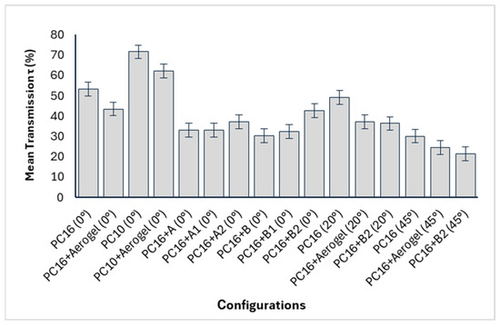
Figure 10.
Mean solar transmission (τ) for all tested SAHF configurations. Error bars represent the standard deviation (±SD) of five repeated measurements for each configuration.
3.2.1. Effect of Silica-Aerogel on PC16 and PC10 Configurations
Figure 11 illustrates the impact of Silica-Aerogel integration on the solar transmission performance of PC10 and PC16 polycarbonate panels. The PC16 configuration without aerogel shows a solar transmission factor (τ) of approximately 53.4%, in this case the reduction factor (RF) is not indicated since this configuration serves as the reference. The PC10 polycarbonate without aerogel shows a higher transmission factor of about 74.0%, due to its thinner and more transparent structure. While this configuration offers improved optical transmittance, its small thickness resulted in limited thermal resistance compared to the PC16. When Silica-Aerogel is added, an improvement in insulation is observed. For PC16 + Aerogel, the RF is about 18.5%, and the solar transmission drops to approximately 44.0%, indicating a reduction in the solar transmission due to the higher solar absorptance determined by the presence of aerogel. This behaviour was clearly documented in [8]. Similarly, the PC10 + Aerogel configuration achieves an RF of 12.7% and a τ of about 63.5%. These results confirm that Silica-Aerogel slightly reduces solar gain in both configurations. However, the observed increase in thermal resistance, reaching up to 33% for the aerogel-filled PC16, highlights its potential as an effective solution to avoid the dissipation of the solar heat gains.
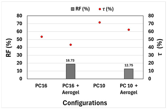
Figure 11.
Reduction factor (RF) and solar transmission (τ) of PC16 and PC10 Configurations with and without Silica-Aerogel.
3.2.2. Effect of Lamellas Coating and Size
In this analysis, each lamella configuration exhibited distinct solar transmission and thermal performance characteristics, according to the lamella coating and width. The Reduction Factor (RF) quantifies the ability of the lamellas to reduce solar transmission, compared to the unshaded polycarbonate layer (PC16), while the solar transmission ratio (τ) indicates the portion of sunlight transmitted through each configuration. As shown in Figure 12, the aluminium-coated lamella (A2 and B2) demonstrates the lowest RF values, thus making it the most favourable for applications that prioritize solar energy gains. The RF of the narrower (2 cm) aluminium-coated lamella (B2) is 19.86%, and there is a high solar transmission ratio of 42.82%, thus highlighting its efficient balance between solar gain and minimal shading. The wider (3 cm) version (A2) shows an RF of 30.44% and a τ of approximately 31.5%, thus indicating increased shading and lower transmission than the B2 configuration.
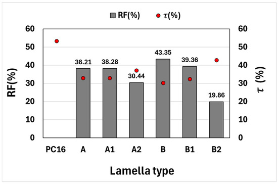
Figure 12.
Reduction factor (RF) and solar transmission (τ) of the different lamella types.
The white-coated lamella (A1 and B1) presents an intermediate performance. The 2 cm variant (B1) achieved an RF of 39.36% and a transmission ratio of 32.40%, while the 3 cm version (A1) shows a similar RF of 38.28%, with a lower τ of around 27.0%. These results indicate that the white coating exhibits moderate reflectivity that is predominantly diffuse rather than specular, while wider configurations show reduced transmission because of the increased shading effect.
The uncoated wooden lamella (A and B) produced the highest RF values, thus suggesting a strong solar blocking capacity. As can be seen in the figure, the 2 cm lamella (B) has an RF of 43.35% and a τ of 30.27%, while the 3 cm version (A) exhibits an RF of 38.21% and a τ of around 26.5%.
These findings confirm that the aluminium-coated lamellas, particularly B2, were the most effective in maximizing solar transmission while minimizing shading, due to their capability of specularly redirecting the solar beams to the translucent surface of the solar façade. The uncoated wooden and white-coated lamellas instead provided enhanced shading and reduced transmission.
3.2.3. Effect of Solar Angle Variations
The effect of Silica-Aerogel integration on the solar transmission ratio (τ) and reduction factor (RF) is shown in Figure 13a. PC16 exhibits the highest solar transmission ratio, that is, of 53.43% at an incidence angle of 0°, which highlights its ability to allow a substantial solar transmission. When Silica-Aerogel is incorporated, the solar transmission decreases to 43.42%, which reflects the impact of Silica-Aerogel on reducing solar transmission while enhancing insulation. In terms of RF, the PC16 + Aerogel configuration achieves a value of 18.73%, thus revealing its reduction in solar transmission, compared to the baseline PC16. The solar transmission ratios decline at 20°, due to the incidence angle. The PC16 configuration exhibits a solar transmission of 48.68%, while the addition of Silica-Aerogel reduces the solar transmission to 37.42%. The reduction factor for PC16 + Aerogel increases to 23.13%, thus indicating its transmission decay at this intermediate angle. Solar transmission at 45° experiences the most significant drop. The PC16 configuration achieves a ratio of 30.12%, while the ratio of the PC16 + Aerogel configuration reduces to 24.37%. The reduction factor for PC16 + Aerogel is 19%. Therefore, it can be concluded that the effect of the aerogel on reducing solar transmission is greater for lower incidence angles. From the practical standpoint, this could lead to a performance penalty during the mid-winter season, when the solar height is lower.
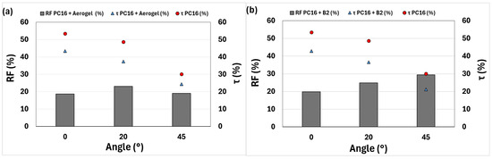
Figure 13.
Impact of the solar incidence angle (0°, 20°, 45°) on the reduction factor (RF) and solar transmission (τ) for (a) PC16, compared with PC16 + Aerogel, and (b) PC16, compared with the PC16 + B2 lamella.
The influence of the reflective aluminum lamella (B2) on τ and RF is presented in Figure 13b. PC16 exhibits the highest solar transmission ratio, that is, of 53.43% at an incidence angle of 0°. The PC16 + B2 configuration achieves a comparable solar transmission value of 42.82%, thus indicating the reflective capability of the aluminum coating to specularly redirect solar beams while maintaining a reasonable transmission value. In terms of RF, the PC16 + B2 configuration achieves a value of 19.86% and shows a reduction, compared to the baseline PC16. The PC16 configuration exhibits a transmission of 48.68% at 20°, while the PC16 + B2 configuration achieves 36.54%. The reduction factor for PC16 + B2 increases to 24.94%. The PC16 configuration achieves a ratio of 30.12% at 45°, while the PC16 + B2 configuration reduces its transmission to 21.25%. The reduction factor for PC16 + B2 rises to 29.43%, which is slightly lower than the ~33.3% surface coverage of the lamella.
In addition, the combined configuration integrating both lamella (A) and Silica-Aerogel (PC16 + A + Aerogel) was preliminarily tested at 0°, corresponding to the most favorable solar incidence angle. The results revealed a solar transmission ratio of 27.99% and a reduction factor of 47.61%, confirming that the combination leads to a substantial attenuation of transmitted solar radiation. This significant reduction at normal incidence suggests that the combined system would exhibit even higher reduction factors at tilted angles, further limiting its solar heat gain potential during winter conditions. Therefore, the configuration was not further investigated experimentally, as its optical penalties can potentially outweigh the expected benefits of the additional thermal insulation.
4. Heat Balance Estimation and Performance Evaluation of SAHF
A simplified steady-state heat balance model was used to estimate the net thermal performance of the different SAHF configurations (Equation (4)). The model is intended to capture the main energy exchanges within the façade, while neglecting solar absorption and heat emission inside the cavity. Thermal inertia and non-uniform solar distribution are also not considered, consistent with the simplified steady-state assumption.
We referred to a full-scale monitoring campaign carried out on an SAHF Trombe wall during the 2023–2024 heating season in Turin (Italy) to ensure that the assessment reflected realistic operating conditions [31]. We estimated Qnet, which is the net heat gain of the SAHF cavity, using these reference values for each tested configuration, thereby accounting for the absorbed solar radiation and the thermal losses to the exterior. This approach allowed us to evaluate whether the configuration that had been validated at a small-scale could maintain sufficiently good performance under real-scale conditions. Although these estimations do not fully replicate conditions or long-term measurements, they provide a reliable framework that can be used to verify the thermal suitability of each configuration for building integration purposes, and they are intended as an initial criteria to select the most promising solutions for future integrations at a larger scale.
The first graph (Figure 14a) illustrates the cumulative frequency distribution of the air temperature differences (ΔT) between the solar façade cavity and the outdoor environment. It shows that ΔT remained below 6 °C, which corresponds to nocturnal or low solar radiation conditions, during approximately 30% of the monitoring period. The median ΔT value is around 11 °C. Moreover, 90% of the values are below 20 °C.
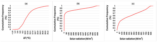
Figure 14.
Cumulative frequency distribution of the real scale SAHF: (a) temperature difference (ΔT), (b) solar radiation (W/m2), considering a period of 24 h, and (c) solar radiation (W/m2), considering only daytime hours.
The second graph (Figure 14b) presents the cumulative frequency distribution of the incident solar radiation measured over the same period. About 30% of the radiation values are below 100 W/m2, thereby reflecting frequent low-radiation conditions. The median value is approximately 250 W/m2, while 90% of the irradiance values remain below 500 W/m2.
Finally, Figure 14c refers to the cumulative distribution of solar radiation during daytime hours and reveals that 60% of the data correspond to irradiance levels below 600 W/m 2, thereby highlighting the stronger impact of solar gains during daytime.
A representative range of environmental conditions was defined, on the basis of these cumulative distributions, to support the heat balance estimation. Specifically, solar radiation values of 150 W/m2, 250 W/m2, and 400 W/m2 were selected to reflect the low, medium, and high irradiance scenarios that were observed during the winter monitoring campaign. Similarly, air temperature differences (ΔT) of 5 °C, 15 °C, and 25 °C were chosen to represent a gradient from minimal to substantial thermal differentials between the façade cavity and the outdoor environment.
- At (0°) incidence angle (Figure 15): At 150 W/m2, PC16 showed 69 W/m2 of average heat gains for ΔT = 5 °C, but dropped to 24 W/m2 for ΔT = 25 °C. The PC16 + Aerogel reached 28 W/m2 for ΔT = 25 °C, thereby slightly improving the performance. The lamellas significantly reduced the performance, with B1 at –8 W/m2 and B2 at 8 W/m2, thus confirming the dominance of heat losses for low irradiance. At 250 W/m2, PC16 recorded 100 W/m2 for ΔT = 15 °C, while PC10 + Aerogel achieved the highest value (127 W/m2), thus underlining the benefit of Aerogel in reducing losses. The lamella configurations remained lower, with B2 at 73 W/m2, and they outperform B1 (25 W/m2). The gains were at a maximum of a 400 W/m2: PC10 + Aerogel reached 240 W/m2 for ΔT = 5 °C, a result that was significantly above that of PC16 (202 W/m2). B2 maintained its reliable performance (138 W/m2 for ΔT = 15 °C), while B1 remained less effective (96 W/m2).
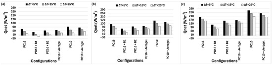 Figure 15. Comparison of (Qnet) for the 0° incidence angle for all the SAHF configurations considering three solar radiation intensities: (a) 150 W/m2, (b) 250 W/m2, and (c) 400 W/m2.
 - At (20°) incidence angle (Figure 16): At 150 W/m2, PC16 reached 17 W/m2 of average heat gains for ΔT = 25 °C, while PC16 + Aerogel recorded 19 W/m2 and B2 fell to –1 W/m2. At 250 W/m2, PC16 achieved 139 W/m2 for ΔT = 25 °C, while Aerogel improved by about 112 W/m2. B2 remained competitive at 90 W/m2 and was once again more performant than B1 (65 W/m2). At 400 W/m2, PC16 showed 183 W/m2 for ΔT = 5 °C, but PC16 + Aerogel demonstrated a higher efficiency at 112 W/m2 for ΔT = 25 °C. B2 show slightly lower performance with 90 W/m2 of average heat gains, whereas B1 underperformed
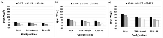 Figure 16. Comparison of (Qnet) for the 20° incidence angle for all the SAHF configurations considering three solar radiation intensities: (a) 150 W/m2, (b) 250 W/m2, and (c) 400 W/m2.
 - At (45°) incidence angle (Figure 17): At 150 W/m2, PC16 provided 34 W/m2 of average heat gains for ΔT = 5 °C, but dropped to –11 W/m2 for ΔT = 25 °C. Aerogel mitigated the loss (−1 W/m2), while B2 showed the lowest value (−24 W/m2). At 250 W/m2, PC16 showed 139 W/m2 for ΔT = 25 °C, while it reached 112 W/m2 with Aerogel. B2 remained lower (90 W/m2), although it was still more performant than B1. At 400 W/m2, PC16 reached 183 W/m2 for ΔT = 5 °C and 139 W/m2 for ΔT = 25 °C. Aerogel performed in a similar manner, that is, from 142 to 112 W/m2, while B2 indicated from 135 to 90 W/m2, thereby showing the strongest shading effect for the high tilt angles.
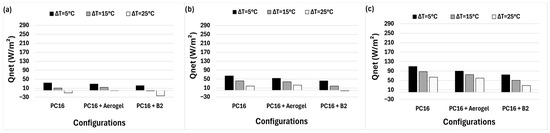 Figure 17. Comparison of (Qnet) for the 45° incidence angle for all the SAHF configurations considering three solar radiation intensities: (a) 150 W/m2, (b) 250 W/m2, and (c) 400 W/m2.
A consistent trade-off emerged for all the incidence angles between thermal insulation and solar transmission. The Silica-Aerogel configurations demonstrated clear advantages at higher temperature differences. The lamella component, that is, the white-coated lamella (B1), provided limited benefits, whereas the aluminium-coated lamella (B2) performed always better than B1, as it redirected part of the incident radiation into the cavity, especially for intermediate ΔT values. The solar gains were maximized for normal incidence (0°), while the differences between materials were more pronounced, with PC10 + Aerogel showing the best performance under high irradiance. Overall, Qnet decreased for realistic tilted angles (20° and 45°), due to a reduced solar penetration, but the relative benefits of Silica-Aerogel insulation and the reflective lamellas became more evident, thereby underlining their role in enhancing energy efficiency.
To complement the analysis of solar heat gains, a simplified steady-state approach was applied to quantify the conductive heat losses during daytime and nighttime periods. The method assumes constant temperature differences between the cavity and the exterior of 15 °C for daytime and 9 °C for nighttime, which correspond to the monitored average temperature gradients in Turin during the winter season of [31]. The durations of 8.5 h and 15.5 h were selected based on the average seasonal daylight hours and nighttime hours, respectively. The energy balance was calculated considering a 20° solar incidence angle, which represents the average winter solar altitude in Turin, ensuring a more realistic assessment of the system’s performance. This calculation isolates the conductive component of thermal exchange to enable a 24 h energy balance, combining both solar gains and heat losses. As shown in Table 4, the Aerogel-filled panels exhibit the lowest energy losses throughout the day and night.
Table 4.
Average daily daytime and nighttime conductive heat losses (Wh m−2 day−1), daytime solar heat gains, and net daily heat balance for SAHF configurations at 20° solar incidence. (Positive (+) values indicate heat gains, while negative (–) values represent heat losses from the system.
It should be noted that this simplified heat balance model presents some limitations, as detailed in Section 4. However, despite these simplifications, this approach provides a reliable framework that can be used to compare different SAHF configurations under realistic climatic conditions.
5. Conclusions
The integration of Silica-Aerogel and lamella elements in façade systems enhances both the thermal insulation and solar control of a building, and it offers a strategic balance between energy conservation and solar harvesting performance. On the thermal side, the obtained results show that filling polycarbonate panels with aerogel led to a substantial reduction in the U-value, and a minimum of 1.19 W/m2 K was reached for the 20 mm-thick panel, which corresponds to a 41.8% reduction, compared to the same panel filled with air. This outcome highlights the effectiveness of the nanoporous structure of aerogel in suppressing the transfer of conductive and convective heat. In parallel, the solar performance evaluations of the various lamella and Silica-Aerogel configurations revealed important trade-offs between the solar transmission ratio (τ) and the reduction factor (RF). The base PC16 configuration showed a high solar transmission value (τ ≈ 53.43%), while the addition of Silica-Aerogel reduced it to approximately 43.42%, thus offering improved thermal insulation and making it more suitable for cold climates. The aluminium-coated lamellas (B2) provided the best solar control, with a transmission of 42.82% for normal incidence and an RF of 29.43% at 45°, thus demonstrating an excellent ability to redirect solar radiation toward the transparent façade element. The heat balance between the cavity and the external environment (Qnet) was estimated to assess the possibility of real-world applications using data from a full-scale SAHF monitoring campaign conducted during the 2023–2024 winter season. The results confirmed that the Silica-Aerogel configurations offered measurable thermal benefits in low irradiance and high ΔT conditions (cold climates), while the B2 lamella systems performed best in sunny conditions with moderate temperature differentials (temperate mediterranean climates). Moreover, it should be noted that the application of aluminium top coated lamellas to solar façades represents an interesting way of increasing architectural integration, while maintaining acceptable solar harvesting performances.
Further studies, focused on assessing the performance of different SAHF solutions through full-scale seasonal monitoring, are currently underway to validate the findings obtained from the small-scale prototype experiments.
Author Contributions
Conceptualization, K.F., V.V.C., S.F., V.S. and A.B.; methodology, K.F., V.V.C. and S.F.; investigation, K.F., V.V.C. and S.F.; writing—original draft preparation, K.F. and V.V.C.; writing—review and editing, K.F., V.V.C., S.F., V.S. and A.B.; project administration, V.S., S.F. and A.B.; funding acquisition, V.S. All authors have read and agreed to the published version of the manuscript.
Funding
This research was funded by the European Union—NextGenerationEU under the NODES project, Mission 4 Component 2—ECS00000036, CUP E13B22000020001. Additional funding was provided by the Italian Ministry of University and Research (MUR) through the PRIN project “CHOISIS—Characterization of Innovative and Sustainable Insulating Solutions”, Mission 4—Education and Research, Measure M4C2—Investment 1.1, project code 2022372TM9, CUP F53D23001540006.The APC was funded by the same projects.
Data Availability Statement
The original contributions presented in the study are included in the article, further inquiries can be directed to the corresponding author.
Acknowledgments
The authors gratefully acknowledge the support provided by the NODES and PRIN-CHOISIS research projects, which served as the framework for the experimental activities presented in this work. The authors also thank Pierpaolo Nuzzo for his valuable technical assistance during the preparation and assembly of the samples.
Conflicts of Interest
The authors declare no conflicts of interest. The funders played no role in the design of the study; in the collection, analyses, or interpretation of the data; in the writing of the manuscript; or in the decision to publish the results.
Abbreviations
| Symbol/Term | Description | Unit |
| g | Solar transmittance of the glazing material | – |
| I | Incident solar irradiance | W/m2 |
| Iaverage | Average solar irradiance during the measurement | W/m2 |
| Iinc | Reference solar irradiance without sample | W/m2 |
| Isample | Solar irradiance for the tested configuration | W/m2 |
| qi | Secondary absorbed/re-emitted heat flux | W/m2 |
| qref | Solar heat flux reflected to the exterior | W/m2 |
| qsol | Solar heat flux transmitted into the interior | W/m2 |
| qTR | Heat flux lost to the exterior | W/m2 |
| Qnet | Total solar heat flux entering the interior space | W/m2 |
| R | Thermal resistance | m2·K/W |
| R_si | Thermal resistance of the air layer (interior surface) | m2·K/W |
| R_ase | Thermal resistance of the air layer (exterior surface) | m2·K/W |
| RF | Reduction factor | % |
| Tcav | Cavity air temperature | K |
| Text | Exterior air temperature | K |
| U | Heat transfer coefficient | W/m2·K |
| U-val | Thermal transmittance | W/m2·K |
| τ | Solar transmission ratio | % |
References
- Cao, X.; Dai, X.; Liu, J. Building energy-consumption status worldwide and the state-of-the-art technologies for zero-energy buildings during the past decade. Energy Build. 2016, 128, 198–213. [Google Scholar] [CrossRef]
- Kalogirou, S.A. Building integration of solar renewable energy systems towards zero or nearly zero energy buildings. Int. J. Low-Carbon Technol. 2015, 10, 379–385. [Google Scholar] [CrossRef]
- Isaia, F.; Fantucci, S.; Serra, V.; Longo, V. The effect of airflow rate control on the performance of a fan-assisted solar air heating façade. IOP Conf. Ser. Mater. Sci. Eng. 2019, 609, 032008. [Google Scholar] [CrossRef]
- Sun, Y.; Wu, Y.; Wilson, R. A review of thermal and optical characterisation of complex window systems and their building performance prediction. Appl. Energy 2018, 222, 729–747. [Google Scholar] [CrossRef]
- Harish, V.; Kumar, A. A review on modeling and simulation of building energy systems. Renew. Sustain. Energy Rev. 2016, 56, 1272–1292. [Google Scholar] [CrossRef]
- Cuce, P.M.; Şen, H. Numerical analysis of thermal insulation performance of double glazing products using air, argon and krypton. In Proceedings of the II-International Conference on Global Practice of Multidisciplinary Scientific Studies, Batumi, Georgia, 26–28 July 2022; Available online: https://www.researchgate.net/publication/366953270 (accessed on 1 October 2025).
- Moretti, E.; Zinzi, M.; Merli, F.; Buratti, C. Optical, thermal, and energy performance of advanced polycarbonate systems with granular aerogel. Energy Build. 2018, 166, 407–417. [Google Scholar] [CrossRef]
- Jia, G.; Li, Z.; Liu, P.; Jing, Q. Preparation and characterization of aerogel/expanded perlite composite as building thermal insulation material. J. Non-Crystalline Solids 2018, 482, 192–202. [Google Scholar] [CrossRef]
- Buratti, C.; Merli, F.; Moretti, E. Aerogel-based materials for building applications: Influence of granule size on thermal and acoustic performance. Energy Build. 2017, 152, 472–482. [Google Scholar] [CrossRef]
- Dorcheh, A.S.; Abbasi, M. Silica aerogel; synthesis, properties and characterization. J. Mech. Work. Technol. 2008, 199, 10–26. [Google Scholar] [CrossRef]
- Cuce, E.; Cuce, P.M.; Wood, C.J.; Riffat, S.B. Toward aerogel based thermal superinsulation in buildings: A comprehensive review. Renew. Sustain. Energy Rev. 2014, 34, 273–299. [Google Scholar] [CrossRef]
- Berardi, U. The development of a monolithic aerogel glazed window for an energy retrofitting project. Appl. Energy 2015, 154, 603–615. [Google Scholar] [CrossRef]
- Wu, L.; Zhao, B.; Gao, D.; Jiao, D.; Hu, M.; Pei, G. Solar transparent and thermally insulated silica aerogel for efficiency improvement of photovoltaic/thermal collectors. Carbon Neutrality 2023, 2, 6. [Google Scholar] [CrossRef]
- Yuan, J.; Jiao, Z.; Chai, J.; Farnham, C.; Emura, K. Reflective coatings: Enhancing building performance and sustainability. Nano-Struct. Nano-Objects 2024, 39, 101296. [Google Scholar] [CrossRef]
- Zhao, L.; Bhatia, B.; Yang, S.; Strobach, E.; Weinstein, L.A.; Cooper, T.A.; Chen, G.; Wang, E.N. Harnessing Heat Beyond 200 °C from Unconcentrated Sunlight with Nonevacuated Transparent Aerogels. ACS Nano 2019, 13, 7508–7516. [Google Scholar] [CrossRef]
- Qiu, Y.; Zhang, Y.; Li, Q.; Xu, Y.; Wen, Z.-X. A novel parabolic trough receiver enhanced by integrating a transparent aerogel and wing-like mirrors. Appl. Energy 2020, 279, 115810. [Google Scholar] [CrossRef]
- Zhao, L.; Bhatia, B.; Zhang, L.; Strobach, E.; Leroy, A.; Yadav, M.K.; Yang, S.; Cooper, T.A.; Weinstein, L.A.; Modi, A.; et al. A Passive High-Temperature High-Pressure Solar Steam Generator for Medical Sterilization. Joule 2020, 4, 2733–2745. [Google Scholar] [CrossRef]
- Lv, Y.; Wu, H.; Liu, Y.; Huang, Y.; Xu, T.; Zhou, X.; Huang, R. Quantitative research on the influence of particle size and filling thickness on aerogel glazing performance. Energy Build. 2018, 174, 190–198. [Google Scholar] [CrossRef]
- Guo, W.; Qiao, X.; Huang, Y.; Fang, M.; Han, X. Study on energy saving effect of heat-reflective insulation coating on envelopes in the hot summer and cold winter zone. Energy Build. 2012, 50, 196–203. [Google Scholar] [CrossRef]
- Levinson, R.; Berdahl, P.; Akbari, H.; Miller, W.; Joedicke, I.; Reilly, J.; Suzuki, Y.; Vondran, M. Methods of creating solar-reflective nonwhite surfaces and their application to residential roofing materials. Sol. Energy Mater. Sol. Cells 2007, 91, 304–314. [Google Scholar] [CrossRef]
- Anestopoulou, C.; Efthymiou, C.; Kokkonis, D.; Santamouris, M. On the development, testing and performance evaluation of energy efficient coatings for buildings. Int. J. Low-Carbon Technol. 2016, 12, 310–322. [Google Scholar] [CrossRef][Green Version]
- Malz, S.; Krenkel, W.; Steffens, O. Infrared reflective wall paint in buildings: Energy saving potentials and thermal comfort. Energy Build. 2020, 224, 110212. [Google Scholar] [CrossRef]
- 4. Digital and Sustainable Mountain|Nord Ovest Digitale e Sostenibile. Available online: https://ecs-nodes.eu/en/4-digital-and-sustainable-mountain (accessed on 10 October 2025).
- BS EN ISO 6946; Building Components and Building Elements. Thermal Resistance and Thermal Transmittance. Calculation Methods. BSI British Standards: London, UK, 2017. [CrossRef]
- C16 Committee; Test Method for Steady-State Thermal Transmission Properties by Means of the Heat Flow Meter Apparatus. ASTM International: West Conshohocken, PA, USA, 2021. [CrossRef]
- DIN 75220:1992-11; Ageing of Automotive Components in Solar Simulation Units. German Institute for Standardisation: Berlin, Germany, 1992.
- CEI EN IEC 60904-3:2020; Photovoltaic Devices—Part 3: Measurement Principles for Terrestrial Photovoltaic (PV) Solar Devices with Reference Spectral Irradiance Data. CEI: Milano, Italy, 2020.
- IEC 60904-9:2020; Photovoltaic Devices—Part 9: Classification of Solar Simulator Characteristics. International Electrotechnical Commission (IEC): Geneva, Switzerland, 2020.
- LP02_manual_v2008_DISCONTINUED.pdf. Available online: https://www.hukseflux.com/uploads/inline/LP02_manual_v2008_DISCONTINUED.pdf (accessed on 11 September 2025).
- Catalogue of the Alveolar Polycarbonate Panels Offered by the Company “Dott. Gallina–Polycarbonate Systems and Sheets”. Available online: https://gallina.it/_files/uploads/download/schede_prodotto/PoliCarb_ita.pdf (accessed on 28 January 2025).
- Karanafti, A.; Badino, E.; Serra, V.; Fantucci, S. Experimental study on the effect of the ventilation and operation mode on the thermal efficiency of a full-scale Trombe wall under real operating conditions. Sol. Energy 2025, 302, 114039. [Google Scholar] [CrossRef]
Disclaimer/Publisher’s Note: The statements, opinions and data contained in all publications are solely those of the individual author(s) and contributor(s) and not of MDPI and/or the editor(s). MDPI and/or the editor(s) disclaim responsibility for any injury to people or property resulting from any ideas, methods, instructions or products referred to in the content. |
© 2025 by the authors. Licensee MDPI, Basel, Switzerland. This article is an open access article distributed under the terms and conditions of the Creative Commons Attribution (CC BY) license (https://creativecommons.org/licenses/by/4.0/).