Abstract
A clearance necessarily exists between the blade tip and the casing in turbines. A leakage flow, formed by the accelerated gas through the tip clearance, is a major cause of turbine stage efficiency loss. Severe heat loads on the blade tip surface also result from a leakage flow, a primary cause of blade damage. Although the understanding of leakage flow mechanisms is mature after years of research, the continuous rise in turbine inlet temperature, pursuing higher engine thrust, requires more effective cooling methods for the blade tip region. This paper presents a review of research on three fundamental tip structures (flat tip, squealer tip, and winglet tip) to explain their design concepts, analyze their respective flow mechanisms as well as heat transfer characteristics, and introduce various modified designs. Various film cooling arrangements applied to these tip structures are examined to identify effective strategies that strengthen the advantages of structural optimization. In view of engineering applications, this paper reviews research on unsteady wake interactions as the aforementioned framework, hoping to provide readers a more comprehensive understanding.
1. Introduction
Gas turbines play a critical role in advanced turbine engines to generate thrust. Modern turbines mainly adopt the axial-flow configuration with multiple stages. Each stage includes a stator mounted on the casing and a rotor mounted on a shaft. The gas, under the guidance of the stator, impinges on the rotor at an incidence angle, forcing the rotor to rotate to generate mechanical energy, which is used to drive the compressor and other components to process the next working cycle. The rotating shaft may experience radial displacement, and the blade exposed to the high-temperature gas will experience spanwise deformation. This leads to an increased possibility of rubbing between blade tips and casing. Maintaining an adequate clearance between them is essential to ensure the safety of these moving and static components. However, partial gas flows through the gap because of the pressure difference between two sides of the blade, which is the leakage flow. The leakage flow contributes to significant efficiency loss, approximately one-third [1,2].
Quantities of research were conducted to clarify the leakage flow mechanism and the associated loss. Not only were experiments conducted using advanced facilities and technologies, but numerical simulation generally became a widely used method as computational codes and commercial software made significant progress. Studies [3,4,5] comparing computational data with experimental results verified the reliability of the numerical simulation. The combined studies based on experimental and numerical approaches helped researchers better understand the flow pattern and heat transfer characteristics, significantly contributing to the development of the cooling system design for turbine blades.
The efficiency penalty of tip loss measured by Booth et al. [6] showed that a 1% additional tip clearance gives 1.5% additional loss. Moore and Tilton [7] further validated the flow patterns involving a vena contracta and described them using a simple two-dimensional model at the foundation of Rains’ research [8]. Based on the above model, a modified equation between the contraction coefficient and the discharge coefficient theory was derived by Heyes et al. [9]. Measurements on velocity field and pressure distribution of leakage flow in clearance were conducted by Sjolande et al. [10] and Yaras et al. [11], and the detail structures were obtained. Bindon [12] explained the formation of leakage flow loss dominated by separation bubbles. Dishart and Moore [13] and Yaras and Sjolander [14] investigated the leakage loss under different clearance conditions, and the aforementioned theories about discharge coefficient and separation bubble were referenced, providing a more accurate method for loss prediction.
Achieving higher efficiency must be established on the foundation that the turbine blade can operate normally. The main reason for blade damage, even failure, is the severe heat load. The temperature of the leakage flow significantly exceeds the material limit, and the turbine inlet temperature increases with the engine development to obtain more powerful thrust. As a consequence, a thorough understanding of heat transfer characteristics and the development of an effective cooling system are the essential parts of the turbine blade design. Given the complex three-dimensional flow field within the tip gap that creates nonuniform heat transfer coefficient distributions with localized peak magnitudes on the tip, the acquisition of detailed heat transfer coefficient profiles becomes not only a prerequisite for blade tip cooling design but also a critical criterion for solution effectiveness validation. Historically, modification of tip geometry to mitigate leakage flow or alter flow field distribution has always been a normal strategy for reducing heat transfer coefficients in tip region. A detailed review of structure design will be presented in a later section. Film cooling is one of the common cooling methods to protect blades from extremely high heat load. Coolant flow generated within the compressor and transferred through the blade’s internal cooling channel is ejected from the film cooling hole to protect the local surface from high temperature gas over-tip leakage, effectively reducing the localized heat transfer coefficient. Research focusing on enhancing film cooling effectiveness has been widely conducted and will be reviewed in detail in the subsequent section.
This paper provides a review based on different tip geometries to explain their design concepts, analyze their respective flow field characteristics as well as heat transfer characteristics, and introduce various optimized designs. Different combinations of film cooling configurations and various blade tip structures are systematically reviewed, with the aim of exploring efficient solutions where structural optimization and cooling strategies mutually enhance advantages of each other. Not only steady conditions but unsteady conditions are also taken into consideration to gain deeper insights into the effects of wake interaction.
2. Flat Tip
A flat tip is the simplest and most basic of all the blade tip structures. It acts as both the primary research subject and the essential comparison standard for subsequent investigations. Figure 1 shows the basic flow pattern of over-tip leakage for an unshrouded flat tip. The leakage flow is driven by the pressure gradient through the tip clearance. After exiting the clearance, the leakage flow mixes with the mainstream flow, forming a leakage vortex and generating significant mixing losses. Figure 1b illustrates the simple model of tip clearance flow on the plane normal to the camber line of a flat tip. After the leakage flow accelerates into the gap from the pressure side, the abrupt narrowing of the passage induces a vena contracta phenomenon. Additionally, a separation bubble exists near the pressure side on the tip. Depending on the blade thickness (accurately the ratio of clearance height to blade thickness), the leakage flow exhibits differences in flow attachment or not, downstream of the separation bubble. Yaras et al. [11] found that the separation bubble occupied a larger proportion as the tip clearance increased, while the discharge coefficient showed a decreasing trend with increasing tip clearance, indicating that the effective flow area was reduced by the separation bubble. The experimental results of Heyes et al. [9] were in agreement with the conclusion of Yaras et al. [11] and indicated that the discharge coefficient should be decreased to achieve a reduction in the all over losses. Moore et al. and Bindon et al. [15,16] concluded that the vena contracta significantly contributed to the localized high heat transfer coefficients and the burnout of the blade pressure side.

Figure 1.
Schematic diagram of leakage flow for a subsonic flat tip. (a) Schematic diagram of the basic form of over tip leakage; (b) schematic diagram of the gap flow [1,17].
Research by Mayle and Metzger [18] on simulated two-dimensional heat transfer revealed that the leakage flow and the relative blade-to-endwall motion were the primary factors influencing blade tip heat transfer. Local heat fluxes on the flat tip from leading edge to approximately thirty percent chords were obtained by Metzger et al. [19] at two different clearances. Nearly the entirety of heat transfer coefficients on a flat tip were measured by Bunker and Ameri [20]. In the study combining the experimental and numerical methods of Ameri and Bunker [21], an accurate model was built for computation according to the details of the experimental rig. Good agreement was achieved in the comparison of the experimental results and the numerical data. The combined research not only obtained detailed heat transfer coefficients on part of the flat tip but also validated the reliability of the numerical method and the k-ω turbulence model.
Azad et al. [22] measured detailed heat transfer coefficients and static pressure distributions on a blade tip with the GE-E3 profile in a five-bladed stationary liner cascade through the transient liquid crystal technique. They also considered the influence of the tip clearance and the turbulence intensity. The high heat transfer region exhibited a high degree of consistency with the leakage flow path, and the flow path of the leakage flow was changed towards the leading-edge suction side by the decreased tip gap. The decreased tip gap reduced both the leakage flow rate and the associated heat transfer coefficient, while the increased turbulence intensity enhanced the heat transfer where the leakage flow passed through. Yang et al. [23] performed a numerical simulation of the flow and heat transfer in the GE-E3 tip region to validate their model against the experimental data of Azad et al. [22], with good agreement achieved. Calculation results from several different turbulence models were compared to evaluate the effect of different turbulence models. These turbulence models all showed qualitatively consistent results and were quantitatively different from those of the experiment, while the RNG k-ε yielded the best consistency. Effect of tip clearance for the flat tip was included in many studies [24,25], and the general conclusion was that higher clearances compared to lower ones resulted in a higher heat transfer coefficient when other variables were controlled.
Sealing geometries such as ribs, trip strips, pins, and so on were set on a flat tip surface in order to block leakage flow in tip clearance. Rational sealing configuration arrangements can optimize the flow field and reduce the leakage flow rate. On the contrary, improper arrangements may induce more severe flow separation and increase loss. Therefore, investigations on such sealing configuration arrangements were conducted to verify the value of the designs. Saxena et al. [26] investigated the effect on reduction of the leakage flow and heat transfer by several configurations like trip strips and pin fins, as shown in Figure 2. The trip strips perpendicular to the leakage flow direction exhibited the lowest leakage flow rate and the highest overall heat transfer coefficient reduction.

Figure 2.
Schematic diagram of tips from research of Saxna et al. [26].
Kwak et al. [27] studied the film cooling effectiveness on the first-stage blade tip of an aircraft engine turbine (GE-E3). There were 13 film cooling holes along the camber and on the pressure side. Two arrangements were studied (ejection only from the tip and from both the tip as well as the pressure side). Three tip gap clearances and three blowing ratios were the controlled variables. Higher film cooling effectiveness was obtained with the larger tip gap. The increasing blowing ratio resulted in an increase in film cooling effectiveness. Compared with injection from the tip hole only, injection from both the tip and pressure side holes provided lower heat transfer coefficients and better film cooling effectiveness.
Under typical engine operating conditions, the blade tip flow is primarily transonic. The transonic flow is accompanied by complex phenomena such as shock wave generation, flow separation, and reattachment variations, which significantly influence heat transfer on a blade tip. Following extensive exploration of characteristics of blade tip heat transfer under subsonic conditions, researchers began to pay increased attention to investigating heat transfer performance on transonic blade tips. A primary issue was whether the conventional pressure-driven wisdom still maintained its applicability under transonic conditions, serving as the basis for research as it did in subsonic conditions. Zhang and He [28] carried out a study for conditions ranging from subsonic to transonic. Different flow patterns were observed between subsonic and transonic conditions. The contour of the Mach number along a plane for subsonic and transonic tip flow is shown in Figure 3. From the results, a large portion of the tip region experiencing transonic flow was observed to be choked, which was also reported by Shyam et al. [29]. The choking limited the overall leakage flow rate. The influence from the suction side was also mitigated, which resulted in the pressure difference between the pressure and suction sides not being the dominant influence of the leakage flow rate. The choking was believed to be advantageous for designing a high-load blade due to its suppression of leakage flow. Wheeler et al. [30] used a CFD code to compare the nature of heat transfer on the blade tip in subsonic and transonic conditions; significant differences were observed. These transonic flow features included the form of the shock wave and the halving of the length of the separation bubble, which were in agreement with the study of Zhang and He [28]. The shortening of the separation bubble was due to the supersonic acceleration of the mainstream flow passing over the separation zone, which generated a stronger pressure gradient that forced the separated flow to reattach. These phenomena resulted in lower turbulence production. The weakened turbulent mixing in the transonic tip region was responsible for the reduction in heat load, in contrast to the low-speed condition. High-speed flow was less dominated by turbulent dissipation compared with low-speed flow, leading to less differences in the choice of turbulence model. Zhang et al. [31] accurately described the high-speed nature of the blade tip. The flow over the first 30% of the axial chord was subsonic and the leading-edge region exhibited higher heat transfer compared to the downstream transonic area. The multiple and repeated heat transfer variations in the form of stripes were first observed in the supersonic part of the tip. The inner link between these stripes and the patterns of shock wave initiation and reflection was explained. Additionally, the influence of clearances on heat transfer of a transonic blade tip was studied by Zhang et al. and Anto et al. [32,33], among others.

Figure 3.
Mach number contours along an axial cut plane from research by Zhang and He. (a) Subsonic tip flow, exit Mach number of 1.01; (b) transonic tip flow, exit Mach number of 0.37 [28].
After reviewing the preceding article, we can find that the understanding of the flat tip demonstrates a spiral progression. The principles of driven pressure difference, vena contracta, and pressure bubble theory have guided the design for reducing blade loss. Recognizing the need to ensure blade protection while enhancing efficiency, research on blade cooling has gained significant attention. After substantial advancements in subsonic blade studies, subsequent research into transonic blades has further filled the knowledge gaps. The flat tip, as the most conventional blade tip profile, frequently serves as a contrast for evaluating the performance of more complex tip designs. Consequently, its characteristics will be discussed further in the subsequent sections where relevant comparative studies are presented.
3. Squealer Tip
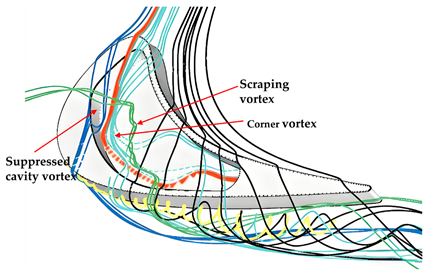
It is known that a smaller tip clearance brings lower losses and lower heat load, but it will increase the risk of the blade tip rubbing into the casing, accordingly. The contradiction can be effectively solved by using a squealer tip. The squealer tip is characterized by a recessed cavity on a flat tip. The thin wall surrounding the cavity is the squealer rim that serves as a sacrificial feature. Even if rubbing occurs, only part of the rim will be damaged without compromising the integrity of the main blade body. Therefore, the effective tip clearance is decreased by decreasing the gap between the rim top and the casing. In addition, the cavity functions as a labyrinth seal to resist leakage flow [34]. From the oil flow visualization shown in Figure 4, the flow in the flat tip gap maintains a predominantly axial flow direction, while the flow within the cavity exhibits a component of streamwise velocity [35], demonstrating a lower velocity in the cavity. The leakage flow rate was verified to be reduced by using squealer tips [9]. Mischo et al. [36] predicted three-dimensional flow through a squealer tip, as shown in Figure 5. The complex flow in the cavity of a squealer was characterized by three dominant vortices. The cavity vortex, formed by the separation and roll-up of the rim boundary layers along the cavity bottom corners, extended across both the pressure side and the front suction side. The scraping vortex was generated by the casing boundary layer fluid interacting with leakage flow. The corner vortex developed when jets from the leading edge of pressure side impinged on the suction-side corner.

Figure 4.
Flow visualization of flat and squealer tip [35].

Figure 5.
Three-dimensional CFD predicted flow field in a squealer tip [36].
Numerous studies conducted with different methods have demonstrated a reduced overall heat transfer coefficient relative to flat tips [4,37,38,39,40]. Metzger et al. [37] and Chyu et al. [4] used two-dimensional tip models to study the heat transfer on squealer tips with varying cavity depth-to-width and tip gap-to-width ratios, and an optimal ratio was obtained. Azad et al. [38] and Kwak et al. [39] measured the all-coverage heat transfer coefficient distribution on the three-dimensional squealer tip, as shown in Figure 6. Yang et al. [40] performed a numerical simulation with boundary conditions consistent with reference [38]. The location of the high heat transfer coefficient on the cavity floor compared with that on the flat tip was found to shift toward the suction side and axially toward the leading edge. However, the rim surface showed higher heat transfer coefficients than the cavity floor, particularly at the trailing edge and the suction side, where the values exceeded those of the corresponding flat tip, while the pressure-side rim was observed to have comparable heat transfer to the flat tip [4,37,38]. Although the numerical predictions by Ameri et al. [41] indicated that the cavity bottom showed higher heat transfer than the flat tip, the predictions for the rim region maintained qualitative consistency with experimental results. In addition, the leading edge at the cavity floor was observed to exhibit a heat transfer peak because of the flow impingement [39,41]. The flow impingement can be recognized clearly in Figure 4, where the dots appear smeared. The squealer tip provided a pronounced reduction in heat transfer coefficients on the shroud compared to the flat tip. However, the reductions for the tip region of two blade sides were comparably not remarkable [39].

Figure 6.
Heat transfer coefficient on squealer tip and flat tip measured by Azad et al. [38].
The width and depth (equivalent to cavity depth) of the squealer rim, typical characteristics of the squealer tip, are fundamental design parameters whose effects should be well understood. Yang et al. [42] and Lee et al. [43] both separately studied five cavity depths. The similar conclusion they reached was that as the cavity depth increased, there existed an optimum value for reducing leakage flow. When the cavity depth exceeded the value, no additional reduction could be obtained. (Especially, Yang et al. [42] identified a 3% cavity depth-to-blade span ratio, while Lee et al. [43] found a 2.75% rim height-to-axial chord length ratio.) On the other hand, heat transfer coefficients exhibited a monotonically decreasing trend as the groove depth increased. Wang et al. [44] and Li et al. [45] investigated different rim widths under subsonic and transonic conditions, respectively. An increased rim width led to a reduction in the heat load on the cavity floor. Each of their smallest widths (0.58% of axial chord in reference [44] and 0.8% of blade height in reference [45]) presented maximum aerodynamic efficiency and the lowest heat transfer coefficient, respectively. The tip clearance influence on the squealer tip was similar to that on the flat tip. Three different tip clearances were studied by Azad et al. [38], and five different tip clearances were taken into consideration by Yang et al. [42]. A larger gap yielded a higher overall heat transfer coefficient, which was attributed to the increased leakage flow rate.
As most of the studies mentioned above were conducted under the condition that the blades were stationary relative to the casing, the validity requires further validation. Experiments by Metzger et al. [37] and Chyu et al. [4] introduced a moving shroud surface aimed at investigating the influence of relative motion and verified the effectiveness of a stationary model in the tip heat transfer investigation. The influence of rotation on the blade tip leakage flow and heat transfer was numerically simulated by Yang et al. [46]. The three simulated rotation conditions included the rotating blade with a stationary shroud, the stationary blade with a rotating shroud, and the stationary blade with a stationary shroud. The main influencing factor of the rotation was the relative motion of the endwall, while the influence of the Coriolis and centrifugal forces played a limited role.
The film cooling effectiveness distribution on the squealer tip was measured by Kwak et al. [47], as shown in Figure 7. The higher blowing ratio could lead to a decreased average heat transfer coefficient. The overall film cooling effectiveness could be enhanced with the increasing blowing ratio but showed no consistent trend across tip gap clearance. Notice should be focused on the fact that, compared with the flat tip, the squealer tip presented higher film cooling effectiveness. He et al. [48] conducted a numerical study on film cooling and heat transfer on the squealer tip investigated in reference [47], with the validation agreeing well with the experimental results. The computational results regarding the effect of tip clearance and blowing ratio remain qualitatively consistent with experimental results. Higher film cooling effectiveness was obtained with coolant injection from both the tip and pressure side holes instead of only injecting from the tip holes. These could be attributed to the blockage of the leakage flow, combined with an expanded region of coolant coverage on the suction side resulting from pressure-side injection. Li et al. [49] studied the effect of tip clearance and cavity depth on pressure loss and cooling effectiveness under a staged environment. They reported that when the cavity depth was increased, the decrease in the leakage flow rate and the enlargement of the cavity vortex occurred simultaneously, resulting in an improvement at first and then deterioration of aerodynamic performance. As the depth increased at a fixed tip clearance, the separation line shifted from the pressure side toward the suction side, altering its position relative to the holes. They suggested that positioning holes on separation lines could enhance cooling effectiveness. Ma et al. [50,51] revealed the interaction between the coolant and leakage flow. The critical flow structure was a counter-rotating vortex pair (CRVP). The CRVP, characterized by its asymmetric strength with a dominant left leg, resulted from the impingement of the coolant on the casing. Strips of high heat transfer coefficient were identified at the upstream subsonic part in the cavity, as shown in Figure 8, because the strength difference induced the leakage flow to move to the cavity floor. At the trailing-edge transonic region, the leakage flow with relatively high momentum was less affected by the cooling flow. An interesting finding was that a reduction in heat flux was observed in regions unreached by injected coolant, confirming that the upstream propagation of the interaction between the coolant and the leakage flow resulted in a reduction in the local heat transfer coefficient.

Figure 7.
The detailed film cooling effectiveness on the squealer tip by Kwak et al. [47].

Figure 8.
Contour of HTC for nine cooling holes by Ma et al. [50].
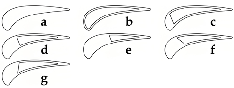
Adjusting the location and quantity of squealer rims was a common approach to modify the squealer tip structure. Azad et al. [52] and Kwak et al. [53,54] studied squealer tips with different rim arrangements. Measurements were conducted on the tip, shroud, and the near-tip regions. The high heat transfer region was related to the reattachment of the leakage flow downstream from the squealer rim. Therefore, different rim arrangements altered the leakage flow path, resulting in significant differences in heat transfer distribution, as shown in Figure 9. The suction-side squealer tip showed the best performance in reducing the heat transfer coefficient. Additionally, the high heat transfer region observed along the suction side corresponded to the leakage vortices developing from the tip or the squealer rim.

Figure 9.
Heat transfer coefficient on squealer tips with different arrangements by Kwak et al. (a) The camber line; (b): the pressure side; (c) the suction side; (d) the pressure and suction sides; (e) the camber line and the pressure side; (f) the camber line and the suction side [53].
Mischo et al. [36] designed an improved squealer tip with nonuniform rim width; the three-dimensional schematic diagram with a cavity flow is shown in Figure 10. Comparing it with the cavity flow of the conventional squealer tip, which is shown in Figure 5, the new design eliminated the suction-side leading edge recirculation zone by optimized profiling, suppressing the cavity vortex. The jet from the pressure-side leading edge was able to spread to the entire cavity floor without localized impingement on the suction-side corner, eliminating the extreme heat region. The scraping vortex broke away from the constraint of the casing and mixed with the pressure-side jet, reducing aerodynamic losses. The improved design simultaneously enhanced total efficiency by 0.38% and reduced the Nusselt number by 7% compared with the conventional squealer tip.

Figure 10.
Schematic diagram of flow field for an improved squealer tip [36].
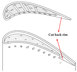
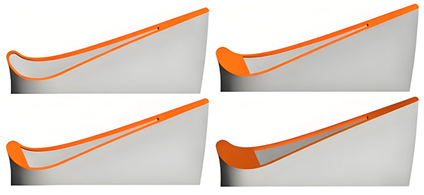
The influence of the partial loss of squealer rim material on turbine blade heat transfer was studied by Bunker and Bailey [55]. Their findings were out of expectation that material loss of the pressure-side rim in the mid-chord region could reduce tip heat transfer, which could be considered an inspiration for the design of partial squealer rims. Camci et al. [56,57] selected an optimal tip structure from several partial squealer tips according to their aerodynamic characteristics. The schematic diagram of these partial squealer rims is shown in Figure 11. The performance of leakage flow reduction and stage efficiency enhancement by suction-side partial squealers performed better than pressure-side partial squealers. Mhetras et al. [58] and Gao et al. [59] investigated the film cooling effectiveness of a partial squealer tip with the pressure side trailing-edge cut. The effects of varying squealer cavity depth, blowing ratios, and coolant injection arrangements were also considered. They concluded that the pressure-side cutback squealer tip provided enhanced cooling effectiveness in the trailing edge compared to the conventional full squealer. Naik et al. [60] compared film cooling effectiveness between a full and a partial squealer tip. The partial squealer tip provided enhanced film cooling at the trailing edge but reduced effectiveness near the leading edge. Lu et al. [61] evaluated two partial squealer tip configurations, featuring a cutback on the pressure-side rim and suction-side rim, respectively. The pressure-side cutback squealer tip suffered a strong impinging leakage flow, leading to an increased heat transfer coefficient near the trailing edge compared with the suction-side cutback design. Due to wiping effect of the high-pressure leakage flow which swept the coolant away from the tip surface, the intended cooling areas could not be covered effectively. Thus, the pressure-side cutback played an inefficient role. In contrast, the suction side cutback effectively enhanced film cooling effectiveness because of the sheltering effect of the pressure-side rim, as the coolant maintains sustained coverage above the cavity floor to the trailing edge.

Figure 11.
Schematic diagram of partial squealer tips designed by Camci et al. [56].
Jeong et al. [62] designed partial cavity tips. In previous studies, a “sweet point” was observed at the flat tip leading edge, and a low heat transfer coefficient could be found at the cavity trailing edge at the squealer tip. Therefore, the partial cavity tips were designed to combine their respective advantages. As shown in Figure 12, these tips featured a flat surface near the leading edge and a cavity extending from mid-chord to the trailing edge. The lowest heat transfer coefficient was achieved by the partial cavity with the cavity extending from the 10% chord, while the highest film cooling effectiveness was yielded by the conventional squealer tip for its uniform coolant distribution and recirculation. Li et al. [63] further studied the influence of a partial cavity on squealer tips with the PW-E3 turbine blade profile. Computational models were obtained by filling the front partial areas of the cavity tip geometry. The size of the pressure-side corner vortex showed a trend of initially increasing and then decreasing as the filling areas increased, and the heat transfer coefficient showed a consistent trend. They suggested that the weakening pressure-side corner vortex correlated with reduced blade tip heat transfer. Enhancing the scraping vortex and suppressing the suction-side corner vortex contributed to a decrease in leakage flow. Du et al. [64] added ribs on the foundation of the partial cavity tip to investigate whether the designs could optimize the heat transfer characteristics. The suction-side rib configuration and the lateral ribs configuration did enhance the aerothermal performance compared to the flat tip. A 27.4% reduction in averaged Nusselt number on the tip surface and a 16.3% decrease in leakage flow were achieved by the suction-side ribbed configuration. The lateral ribs configuration showed an averaged Nusselt number reduction of 27.2% on the tip surface and a 17.3% decrease in leakage flow.

Figure 12.
Schematic diagram of partial cavity tips designed by Jeong et al. [62].
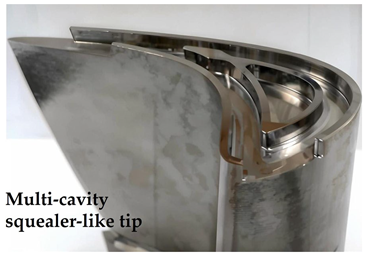
Cernat al. [65] designed a multi-cavity squealer-like tip, with its geometry presented in Figure 13. The multi-cavity squealer-like tip took the partial squealer design with an island closed rim presented in the middle of the outer squealer cavity. The multi-cavity squealer-like tip could limit mid-chord leakage by dual sealing and improve efficiency by 3% over the flat tip. However, a higher heat flux in the casing region was observed due to frequent impacts between the multi-cavity and the casing.

Figure 13.
Geometry of the multi-cavity squealer like tip by Cernat et al. [65].
Park et al. [66] performed experimental and numerical studies into multi-cavity blade tips, which were obtained by separating the cavity with ribs. Du et al. [67] investigated the aerothermal performance of multi-cavity squealer tips. Four ribs were specified as perpendicular to the camber line with equal spacing, dividing the cavity into five small cavities. In addition, according to the number of ribs arranged in the cavity, four cases were distinguished and studied. The rib design was intended to weaken the high heat at the cavity floor due to the reattachment flow. They concluded that the multi-cavity squealer tip showed a lower heat transfer because the reattachment flow was truncated by the ribs. However, regions near the ribs worked more similar to a flat tip, especially the trailing edge. The multi-cavity tip exhibited a higher total pressure loss than the single cavity. Consequently, the five-cavity tip demonstrated the lowest overall heat transfer coefficient but the highest total pressure loss among all configurations. Jiang et al. [68] further optimized the multi-cavity squealer tips. They replaced ribs in five cavity tips with half-ribs of different numbers and locations. The four-rib tip, with half-ribs connected to the pressure side, not only could truncate the reattachment line but also could prevent the deficiency of the trailing-edge aerothermal characteristics from being similar to the flat tip. Therefore, the four-rib tip obtained optimal comprehensive aerothermal performance. Studies on such squealers with ribs in the cavity were also conducted by Park et al. [69], Huang et al. [70], and Bi et al. [71]. Typically, film cooling on similar multi-cavity tips was investigated by Bi et al. [71]. They concluded that although ribs placed mid-chord downstream hindered coolant coverage by altering leakage flow paths, those ribs placed upstream effectively blocked the separation region at the cavity bottom, thereby improving coolant coverage. The multi-cavity tip with two ribs positioned at 10% and 25% chord exhibited optimum performance, demonstrating a superior balance of reducing the leakage flow and heat transfer coefficient while enhancing film cooling effectiveness. Specifically, compared to the uncooled ribless one, this configuration achieved a 24.96% reduction in the averaged heat transfer coefficient and an 18.82% decrease in the leakage flow mass rate.
In summary, the traditional squealer tip configuration demonstrated significant advantages compared to flat tips, including reducing the leakage flow rate, reducing the heat transfer coefficient, and enhancing the film cooling effectiveness. Building on this foundation, researchers have further explored structural modifications on squealer tips to achieve improved aerothermal performance. Initial broad parametric studies investigated critical squealer rim geometry parameters, such as width and height. Subsequent efforts focused on targeted structural designs based on detailed analysis of flow field and heat transfer characteristics, followed by experimental validation. Through advancing design methodologies and increasingly mature research approaches, researchers have made substantial achievements in enhancing tip cooling performance through optimized squealer tip structures. Table 1 summarizes the features and advantages of the squealer tip and its modified designs.

Table 1.
Features and advantages of the squealer tip and its modified designs.
4. Winglet Tip
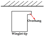
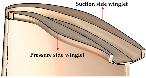
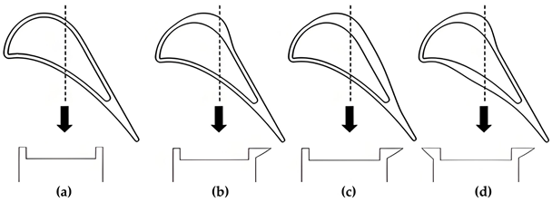
A “winglet” is originally designed for installation at the tips of airplane wings to weaken wingtip vortices and decrease induced drag. The concept of the winglet used in turbine blade tips is a very short extension by extending a tip platform in a tangential direction, as Dey and Camci [72] explained. The concept of the winglet was involved in research by Booth et al. [6]. They intended it to reduce the inlet pressure drop, thus decreasing the pressure difference. The use of the winglet reduced the discharge coefficient by 9% compared to a flat tip, which demonstrated the effect of winglet design in leakage suppression and improving turbine efficiency. Willinger et al. [73] used a simplified model to simulate and predict the discharge coefficient of the winglet tip. Despite a 5% discrepancy from the experimental data of Booth et al. [6], the prediction still demonstrated the effect of reducing leakage flow by the winglet tip. Dey and Camci [72] investigated the use of the pressure-side winglet and suction-side winglet on an axial flow turbine blade tip to reduce the leakage flow with comparison to the flat tip. The pressure-side winglet tip was demonstrated to be an effective design to reduce the jet leaking into the suction side, while the suction-side winglet did not present its effectiveness. Kang and Seo [74,75] studied a flat tip with a full-coverage overhang with the influence of different tip clearances. Mass/heat transfer on the tip and bottom surface of the overhang were analyzed. The mass/heat transfer rate on the bottom surface of the winglet showed a liner negative correlation trend with the tip clearance. The original surface region of the flat tip on the winglet tip was verified to suffer less thermal load than the flat tip, while the overhang region showed higher heat load than the flat tip surface.
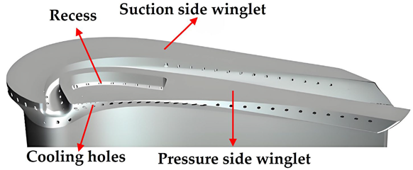
Harvey et al. [76] validated the effectiveness of reducing leakage flow on the unshrouded tip by a new winglet tip design. As shown in Figure 14, there are two winglets with an aerofoil shape at the blade tip, forming a channel and indirectly doubling the number of rotor tips. The prediction indicated that the turbine stage efficiency was improved by 1.2–1.8 percent and the tip loss exchange rate was reduced by 30 percent. Harvey et al. [17] and Willer et al. [77] conducted further investigations on the winglet tip described in reference [76] to consider its partial application value. They proposed that the unshrouded blades with winglets could not replace current full shroud blades in aircraft engines at that time, although the significant effectiveness in reducing leakage flow loss by the winglet was equivalent to a two-fin shrouded tip. For a replacement to be viable, the winglet tip would not only need to perform better than the current design (which has two fins and two fences) but also undergo further improvement. O’Dowd et al. [78] and Zhou et al. [79] investigated the aerothermal performance of a transonic winglet tip. The geometry resembled the winglet design presented by Harvey [76], as seen in Figure 15. The average heat load on the winglet tip was nearly 2.7 times higher than that on a flat tip. This was not a surprising result because the primary design purpose of the winglet was to reduce leakage flow, with cooling achieved through introducing cooling holes on the surface. Zhou et al. [80] and O’Dowd et al. [81] further studied the aerothermal performance of the cooled winglet tip at low-speed and transonic conditions, respectively. The combined effects of relative endwall motion and reduced tip clearance were investigated. Endwall motion reduced the leakage mass flow but increased scraping vortex loss, contributing to a net 15% decrease in tip leakage loss and a 31% reduction in winglet tip heat flux, driven by a 14% lower Nusselt number and 9% higher cooling effectiveness. Smaller tip clearances improved film cooling effectiveness through superior coolant coverage. The winglet tip was also used in a study on wall thermal conditions conducted by Zhang and He [82]. They proposed a challenge to the conventional assumption that the leakage flow characteristics were not influenced by the wall thermal boundary conditions at transonic conditions. The computational results demonstrated that there was a strong two-way interaction between aerodynamics and heat transfer under transonic conditions, and the newly proposed nonlinear correction method obtained a simulation accuracy close to the conjugate heat transfer, improving significantly over the traditional linear method.

Figure 14.
Geometry of the winglet presented by Harvey et al. [76].

Figure 15.
Geometry of the winglet tip studied by O’Dowd et al. [78].
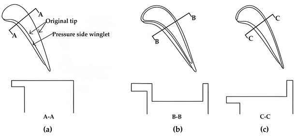
Applying the design concept of winglet to the suction-side squealer tip, research on the winglet–squealer tip configuration was initiated by Papa et al. [83], as shown in Figure 16. They found that the cavity of the winglet–squealer tip yielded a lower mass transfer coefficient compared to the conventional squealer tip. Saha et al. [84] studied the winglet–squealer tip with the winglets extending from the pressure side not only at a suction-side squealer tip but also at a full squealer tip, as shown in Figure 17. Adding a winglet to the flat tip led to a weaker leakage flow and a 7% decrease in the average heat transfer coefficient. For the full squealer tip, however, the winglet had a minimal effect on both leakage and heat transfer. The most significant improvement was observed on the suction-side squealer tip, where the winglet proved most effective, reducing heat transfer by 5.5% and the pressure loss coefficient by 27%. Joo and Lee [85,86] studied winglets extending from the circumferential edge of the squealer tip. The mass/heat transfer rate on the cavity floor of the winglet–squealer tip was lower than that on the winglet surface, and the discrepancy between them decreased as tip clearance increased. The cavity floor provided a lower mass/heat transfer rate by using the winglet at two lower tested tip clearances, but the contrary phenomenon was observed at two higher clearances. Yan et al. [87] studied the suction-side squealer tip with a pressure side winglet of different leading-edge angles and different coverage percentages. The conventional squealer, suction-side squealer tip, and the winglet–squealer tip were compared through numerical methods. They concluded that the removal of the pressure-side rim could weaken the heat transfer on the leading-edge cavity floor. Furthermore, replacing the pressure-side rim with a winglet could further reduce heat transfer while also reducing total pressure loss. The winglet leading-edge angle had little influence on the total pressure loss as well as the heat transfer distribution, although it could optimize localized high heat transfer. There was an optimal coverage percentage of the winglet that could significantly reduce the total pressure loss (13.8% reduction by 80% winglet coverage) and the heat transfer coefficient (15.8% reduction by 60% winglet coverage) in contrast to a conventional squealer tip. Yan et al. [88] conducted a numerical investigation into film cooling characteristics on a winglet–squealer tip based on studies of Kwak et al. [39,47]. The distributions of the heat transfer coefficient and film cooling effectiveness of the squealer tip were consistent with the experimental results. The suction-side squealer tip and the pressure-side winglet tip showed better performance in reducing total pressure loss, heat transfer characteristics, and film cooling effect compared with the conventional squealer tip, especially the pressure-side winglet, yielding the lowest heat transfer. The pressure-side winglet showed a higher film cooling effectiveness than the suction squealer tip under small tip clearance conditions. The authors also proposed that the pressure-side winglet tip was more sensitive to the blowing ratio and coolant ejection angle, which should be further investigated in the geometry optimization study.

Figure 16.
Schematics of winglet–squealer tip by Papa et al. [83].

Figure 17.
Schematics of (a) flat tip with winglet, (b) squealer tip with winglet, and (c) suction-side squealer with winglet [84].
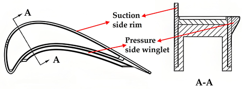
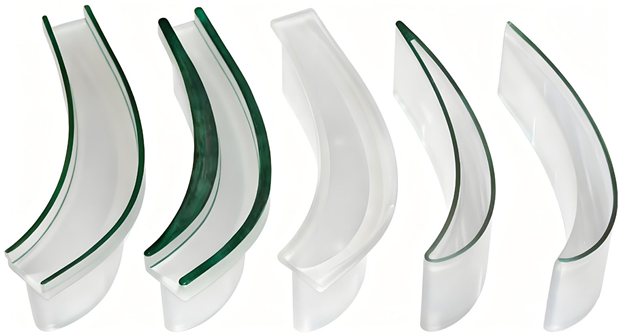
Schabowski and Hodson [89] also studied a kind of winglet–squealer tip, as shown in Figure 18. These winglet–squealer tips were designed by adding squealer rims on the edges of the winglet platforms and were different from the winglet–squealer tips previously referred to, where the winglets extended from the squealer tip. The optimal design was the winglet with thin squealer rims because it had the combined effect of reducing driving pressure by the winglet and leakage flow blockage by the squealer rims. Schabowski et al. [90] then studied the optimization of a winglet–squealer tip. The optimized tip with the suction-side winglet and thin squealers significantly weakened the leakage loss related to the flat tip at all tested exit speed conditions. Jiang et al. [91] designed three squealer winglet structures that extended winglets from the cavity floors of the squealer tips and were equipped with rims at the edge of the winglets, presenting multi-cavity structures. Both reduced the average heat transfer coefficient and reduced leakage flow mass, and both sides of the squealer winglet tip showed the best performance, followed by the suction-side winglet tip. However, concerning the reduction in the total pressure loss coefficient, the suction-side winglet tip was superior to both sides of the squealer winglet tip, but the pressure-side winglet tip demonstrated adverse effects.

Figure 18.
Squealer and winglet geometries in the study of Schabowski and Hodson [89].
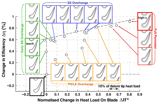
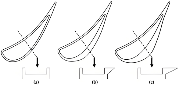
Coull et al. [92] used a novel parameterization method to design the geometry of the winglet tip. Figure 19 shows the change in efficiency and heat load for all designed winglets. It indicated that winglets extending from only the early suction side can significantly improve efficiency without increasing the overall heat transfer. Zhou et al. [93] introduced a novel philosophy to design suction-side winglet tips, driven by an analysis of the near-tip flow field, as shown in Figure 20. The driving pressure difference in the leakage flow was reduced by using the suction-side winglets. The leakage flow loss was also reduced by 18.1% for winglet-2 compared to the cavity tip. However, winglet designs suffered more severe heat load than the cavity tip. Zhong et al. [94,95] designed similar suction-side winglet tips based on the loss mechanism described in reference [93], as shown in Figure 21. A two-sided winglet tip and a small suction-side winglet tip, whose winglet only extended from the leading edge, were considered. The small suction-side winglet tip showed the best aerothermal performance. The design of the winglet not extending to the trailing edge could prevent additional leakage driving forces and high heat load.

Figure 19.
Changes in efficiency and heat load for winglet designs [92].

Figure 20.
Tip geometries of cavity tip (a), winglet 1 (b), and winglet 2 (c) [93].

Figure 21.
Tip geometries of cavity tip (a), winglet 1 (b), winglet 2 (c), and winglet 3 (d) [94].
A winglet on a turbine blade tip is an extending platform extending from the tip surface. Initially proposed with the same objective as the early research of turbine blades, the winglet tip aimed to reduce the leakage flow by decreasing the driven pressure difference across the tip, thereby enhancing the turbine efficiency. By reducing the driven pressure difference across the tip, winglets enhance turbine efficiency. However, their relatively complex geometry and larger surface area necessitate efficient cooling design. Extensive research has not only advanced the understanding of inherent winglet characteristics but also found the excellent performance of the combined design with squealer tips. Furthermore, multi-parameter shape optimization, guided by flow field and heat transfer characteristics, has significantly improved design specificity and effectiveness. Table 2 summarizes the features and advantages of the winglet tip and its modified designs.

Table 2.
Features and advantages of the winglet tip and its modified designs.
5. Unsteady Wake
The studies mentioned above were primarily conducted with steady uniform incoming conditions. This steady-state assumption remains rational and effective for blade design, as it presents performance averaged over extended operational periods. However, such an approach actually neglects some unsteady flow phenomena, particularly the interference caused by stator wakes. Consequently, advancing the understanding of unsteady characteristics is of great importance for gaining deeper insights into blade tip heat transfer mechanisms and further optimizing cooling structure design. In a gas turbine stage, the boundary layer shedding from the trailing edge of the upstream blades forms a wake that influences downstream flow. This wake critically affects turbine performance, influencing efficiency, loss generation, and noise emission. The heat transfer on the blade tip becomes particularly complex because of the interactions between wake and leakage flow boundary layer.
Hodson et al. [96] and Chaluvadi et al. [97] directly measured the unsteady flow field within rotors using pressure probes and a five-hole probe. Unlike measuring stationary a stationary blade, it is difficult to measure the flow field with rotating vanes and rotors. Laser technology measurements were taken by Binder [98], Zaccaria [99], and Göttlich [100] to obtain an unsteady flow field. Simplified experiments were conducted by Doorly [101], Ashworth [102], and Dullenkopf [103]. They used a rotating bar to simulate the motion of an upstream vane, generating an unsteady wake on the stationary blades. In the study of Guenette et al. [104], the effectiveness of this simulation approach was verified. Computational methods for unsteady prediction were developed by Rai et al. [105], Giles et al. [106], and Abhari et al. [107].
Sharma et al. [108] studied the three-dimensional unsteady wake downstream of the vane in a large-scale 1.5 stage turbine rig. They found that although the position of the rotor relative to the wake of the upstream guide vanes continuously changed, the tip leakage vortex itself behaved relatively stable. Zeschky et al. [109], Gallus et al. [110], and Volino et al. [111] also proposed that leakage flow was only slightly influenced by wake, while the leakage vortex had more interaction with the passage secondary vortex, as presented by Payne et al. [112] and Zhou et al. [113].
Ameri et al. [114] conducted a numerical study on the influence of unsteady wake on tip heat transfer. They proposed that the blade tip flow was dominated by the tip leakage flow, whose intensity was strong enough to diminish the effect of the unsteady wake. Therefore, the obtained results showed that the difference between the time-averaged Nusselt number from unsteady calculations and the steady values was small. In fact, the time-averaged results would hide the instantaneous high heat transfer regions, which suffered the most severe damage on the blade tips. This highlighted the necessity of capturing such instantaneous variations depending on unsteady research conditions. In transonic conditions, blade tip heat transfer was investigated by Thorpe et al. [115]. Although the influence of the wake interaction was limited, the interference effect of the vane trailing-edge shock is significant. When the blade’s leading edge approaches the vane, a shock wave generated at the throat between the blade’s leading edge and the vane suction side directly interacted with the tip surface, triggering an instantaneous increase in the heat transfer coefficient. Molter et al. [116], Rahman et al. [117], and Atkins et al. [118] studied the unsteady heat transfer at transonic turbine conditions. Significant pressure fluctuations induced by vane trailing-edge shocks were observed, along with localized severe heat transfer regions driven by unsteady shock–leakage flow interaction, particularly in squealer tips. These studies revealed that time-accurate results could be more representative of the actual gas turbine conditions.
Squealer tip geometries could weaken the influence of unsteady interactions, compared with the flat tip. Saxena et al. [26] found that the wake injecting into the tip gap brought higher turbulence strength, thus enhancing the overall heat transfer, especially at the sweet spot. The full squealer tip demonstrated the lowest heat transfer coefficients under the wake influence among different rim arrangements. An increase in cavity depth [119] or an increase in tip clearance [120] enhanced the influence of unsteadiness on heat transfer. This was because the vortex in the cavity provided a dampening effect on the wakes, preventing the immediate breakdown of the boundary layer that occurred on the flat tip. Furthermore, adding wake interaction with larger tip clearance resulted in higher time-averaged heat transfer. Polanka et al. [121] attributed the variations in flux fluctuations to the pressure fluctuations. In the study of Jiang et al. [122], as the blade tip approached or moved away from the vane wake, the pressure difference correspondingly increased or decreased, subsequently causing fluctuations in the heat transfer coefficient. The use of a multi-cavity tip resulted in elevated fluctuations only within the third and fourth cavities [68]. While the localized heat transfer increased, the overall heat transfer on the multi-cavity remained lower than that of a squealer tip. Zhou et al. [123] investigated vane–blade interaction and tip leakage flow with a winglet–squealer tip. Compared with a flat tip, the winglet–squealer tip significantly reduced the time-averaged leakage flow and increased the time-averaged efficiency. These could be attributed to the weakening of the unsteady interaction by the winglet guiding and stabilizing the leakage flow.
Mehendale et al. and Ou et al. [124,125] studied the influence of wake flow on blade heat transfer and film cooling. Under the interaction of the unsteady wake, the heat transfer coefficient significantly increased, while the film cooling effectiveness decreased with the disruption of film coverage. However, the relative increase in the heat flux without film cooling was higher than that which was cooled, contributing to a decrease in the heat flux ratio. This demonstrated the benefit of film cooling in the unsteady environment of actual turbines. Gao et al. [126,127] also found that the film cooling effectiveness decreased significantly because of the turbulent mixing of coolant and mainstream enhanced by the upstream wake. The compound angle-shaped holes shown in Figure 22 could maintain wider coolant coverage compared to axial-shaped holes under unsteady conditions, providing better cooling performance. Rallabandi et al. [128] found that coolant ejected from the pressure side reattached downstream on the surface, exhibiting higher cooling effectiveness than that from the suction side. They advised using compound angle-shaped holes arranged along the pressure side with high density ratio coolant ejection to reduce the influence of the wake interaction. Zhang et al. [129] investigated the axial arrangement of film cooling holes under unsteady conditions. They proposed that the film cooling holes were not recommended to be arranged at the leading edge. Because the cooling efficiency fluctuated the most at the leading edge due to wake effects, film holes may also disrupt the sweet spot. Jiang et al. [130] and You et al. [131,132] conducted unsteady investigations of film cooling on squealer tips, as shown in Figure 23. A finding reached from their studies was that when the wake interaction was strong, the coolant failed to provide adequate coverage, whereas when the wake interaction weakened, the cooling efficiency significantly improved. This revealed a severe challenge of the temporal mismatch between high cooling efficiency and high heat load. This showed that the key challenge of the temporal mismatch between high cooling effectiveness and high heat loads remained. To mitigate the localized transient overheating, further efforts should be devoted to cooling system improvement.

Figure 22.
The compound angle-shaped holes [127].

Figure 23.
The vorticity contour on a middle plane of the tip clearance at different times [130].
6. Concluding Remarks
Thanks to decades of persistent efforts by researchers, significant progress has been made in fundamental theories, experimental techniques, and CFD technology. Acquiring accurate flow field data and detailed heat transfer distributions has become an advanced capability, and the research focus has shifted from understanding to optimization. To meet the demands of rapidly developing modern gas turbine engines, blade cooling design must keep pace accordingly.
Effective structure design can weaken the leakage flow and reduce the heat transfer coefficient on the tip surface. For the squealer tip, decreasing tip clearance and reducing leakage flow velocity through a sealing effect are the primary functions. While the design philosophy of the winglet tip is to weaken the leakage flow by reducing the driving pressure difference, adjusting these basal tip structures in detail can further weaken the high heat transfer region. Traditional optimization methods, whether through experiments or numerical simulations, demand substantial costs and long time cycles. Depending on machine learning to develop predictive models to assist in design has become an effective way to improve optimization efficiency. The establishment of a predictive model generally involves the following steps. The blade profile is parameterized to generate a certain amount of parameter data sets, which are then simulated. The obtained result files are used to build and train the network, followed by optimizing and validating the predictive model [133]. In this way, as long as the design parameters are input, the machine can provide prediction results. Once this technology matures, it will provide significant support for blade design.
Combining cooling injections with these inherent structure advantages can achieve excellent aerothermal performance. However, complex interactions exist between coolant and leakage flow, and their manifestation varies across different tip geometries. Interactions on the targeted tip are suggested to be studied further. Although substantial research has enhanced our understanding of these effects on normal tips, studies on targeted tip configuration under unsteady interactions are rare. It is worth it to further optimize cooling design for advanced tip configurations under unsteady conditions. This optimization specifically addresses the temporal mismatch between high cooling efficiency and high heat load.
Funding
The authors gratefully acknowledge the support of the National Natural Science Foundation of China (Grant No. 12202192), the Fundamental Research Funds for the Central Universities: Key Laboratory of Aircraft Environment Control and Life Support, MIIT, Nanjing University of Aeronautics and Astronautics (Grant No. KLAECLS-E-202206), and Key Laboratory of Civil Aviation Emergency Science and Technology CAAC (Grant No. XCA2402202).
Conflicts of Interest
The authors declare no conflicts of interest.
References
- Denton, J.D. Loss Mechanisms in Turbomachines; American Society of Mechanical Engineers: New York, NY, USA, 1993. [Google Scholar] [CrossRef]
- Schaub, U.W.; Vlasic, E.; Moustapha, S.H. Effect of tip clearance on the performance of a highly loaded turbine stage. In AGARD, Technology Requirements for Small Gas Turbines; TIB: Hannover, Germany, 1994; 11p, SEEN 94-34431 10-07. [Google Scholar]
- Wadia, A.R. Numerical solution of two-and three-dimensional rotor tip leakage models. AIAA J. 1985, 23, 1061–1069. [Google Scholar] [CrossRef]
- Chyu, M.K.; Moon, H.K.; Metzger, D.E. Heat transfer in the tip region of grooved turbine blades. ASME J. Turbomach. 1989, 111, 131–138. [Google Scholar] [CrossRef]
- Ameri, A.A.; Steinthorsson, E. Prediction of Unshrouded Rotor Blade Tip Heat Transfer. In Proceedings of the ASME 1995 International Gas Turbine and Aeroengine Congress and Exposition, Houston, TX, USA, 5–8 June 1995; Heat Transfer, Electric Power, Industrial and Cogeneration. ASME: New York, NY, USA; Volume 4, p. V004T09A037. [Google Scholar] [CrossRef]
- Booth, T.C.; Dodge, P.R.; Hepworth, H.K. Rotor-Tip Leakage: Part I—Basic Methodology. ASME Eng. Power. 1982, 104, 154–161. [Google Scholar] [CrossRef]
- Moore, J.; Tilton, J.S. Tip Leakage Flow in a Linear Turbine Cascade. ASME Turbomach. 1988, 110, 18–26. [Google Scholar] [CrossRef]
- Rains, D.A. Tip Clearance Flows in Axial Flow Compressors and Pumps. Ph.D. Thesis, California Institute of Technology, Pasadena, CA, USA, 1954. [Google Scholar]
- Heyes, F.J.G.; Hodson, H.P.; Dailey, G.M. The Effect of Blade Tip Geometry on the Tip Leakage Flow in Axial Turbine Cascades. ASME Turbomach. 1992, 114, 643–651. [Google Scholar] [CrossRef]
- Sjolander, S.A.; Amrud, K.K. Effects of Tip Clearance on Blade Loading in a Planar Cascade of Turbine Blades. ASME Turbomach. 1987, 109, 237–244. [Google Scholar] [CrossRef]
- Yaras, M.; Zhu, Y.; Sjolander, S.A. Flow Field in the Tip Gap of a Planar Cascade of Turbine Blades. ASME Turbomach. 1989, 111, 276–283. [Google Scholar] [CrossRef]
- Bindon, J.P. The Measurement and Formation of Tip Clearance Loss. ASME Turbomach. 1989, 111, 257–263. [Google Scholar] [CrossRef]
- Dishart, P.T.; Moore, J. Tip Leakage Losses in a Linear Turbine Cascade. ASME Turbomach. 1990, 112, 599–608. [Google Scholar] [CrossRef]
- Yaras, M.I.; Sjolander, S.A. Prediction of Tip-Leakage Losses in Axial Turbines. ASME Turbomach. 1992, 114, 204–210. [Google Scholar] [CrossRef]
- Moore, J.; Moore, J.G.; Henry, G.S.; Chaudhry, U. Flow and Heat Transfer in Turbine Tip Gaps. ASME Turbomach. 1989, 111, 301–309. [Google Scholar] [CrossRef]
- Bindon, J.P. Pressure Distributions in the Tip Clearance Region of an Unshrouded Axial Turbine as Affecting the Problem of Tip Burnout. In Proceedings of the ASME 1987 International Gas Turbine Conference and Exhibition, Turbomachinery, Anaheim, CA, USA, 31 May–4 June 1987; ASME: New York, NY, USA; p. V001T01A085. [Google Scholar] [CrossRef]
- Harvey, N.W.; Newman, D.A.; Haselbach, F.; Willer, L. An Investigation Into a Novel Turbine Rotor Winglet: Part I—Design and Model Rig Test Results. In Proceedings of the ASME Turbo Expo 2006: Power for Land, Sea, and Air, Turbomachinery, Parts A and B, Barcelona, Spain, 8–11 May 2006; ASME: New York, NY, USA; Volume 6, pp. 585–596. [Google Scholar] [CrossRef]
- Mayle, R.E.; Metzger, D.E. Heat transfer at the tip of an unshrouded turbine blade. In International Heat Transfer Conference Digital Library; Begel House Inc: Danbury, CT, USA, 1982. [Google Scholar] [CrossRef]
- Metzger, D.E.; Dunn, M.G.; Hah, C. Turbine Tip and Shroud Heat Transfer. ASME Turbomach. 1991, 113, 502–507. [Google Scholar] [CrossRef]
- Bunker, R.S.; Bailey, J.C.; Ameri, A.A. Heat Transfer and Flow on the First-Stage Blade Tip of a Power Generation Gas Turbine: Part 1—Experimental Results. ASME Turbomach. 2000, 122, 263–271. [Google Scholar] [CrossRef]
- Ameri, A.A.; Bunker, R.S. Heat transfer and flow on the first-stage blade tip of a power generation gas turbine: Part 2—Simulation results. J. Turbomach. 2000, 122, 272–277. [Google Scholar] [CrossRef]
- Azad, G.S.; Han, J.C.; Teng, S.; Boyle, R.J. Heat transfer and pressure distributions on a gas turbine blade tip. J. Turbomach. 2000, 122, 717–724. [Google Scholar] [CrossRef]
- Yang, H.; Acharya, S.; Ekkad, S.V.; Prakash, C.; Bunker, R. Flow and heat transfer predictions for a flat-tip turbine blade. Turbo Expo Power Land Sea Air 2002, 36088, 271–283. [Google Scholar] [CrossRef]
- Ameri, A.A.; Steinthorsson, E.; Rigby, D.L. Effects of Tip Clearance and Casing Recess on Heat Transfer and Stage Efficency in Axial Turbines. ASME Turbomach. 1999, 121, 683–693. [Google Scholar] [CrossRef]
- Nasir, H.; Ekkad, S.V.; Kontrovitz, D.M.; Bunker, R.S.; Prakash, C. Effect of tip gap and squealer geometry on detailed heat transfer measurements over a high pressure turbine rotor blade tip. J. Turbomach. 2004, 126, 221–228. [Google Scholar] [CrossRef]
- Saxena, V.; Nasir, H.; Ekkad, S.V. Effect of blade tip geometry on tip flow and heat transfer for a blade in a low-speed cascade. Turbomachinery 2004, 126, 130–138. [Google Scholar] [CrossRef]
- Kwak, J.S.; Han, J.C. Heat transfer coefficients and film-cooling effectiveness on a gas turbine blade tip. Heat Transf. 2003, 125, 494–502. [Google Scholar] [CrossRef]
- Zhang, Q.; He, L. Overtip choking and its implications on turbine blade-tip aerodynamic performance. J. Propuls. Power 2011, 27, 1008–1014. [Google Scholar] [CrossRef][Green Version]
- Shyam, V.; Ameri, A.; Chen, J. Analysis of Unsteady Tip and Endwall Heat Transfer in a Highly Loaded Transonic Turbine Stage. ASME Turbomach. 2012, 134, 041022. [Google Scholar] [CrossRef]
- Wheeler, A.P.S.; Atkins, N.R.; He, L. Turbine Blade Tip Heat Transfer in Low Speed and High Speed Flows. ASME Turbomach. 2011, 133, 041025. [Google Scholar] [CrossRef]
- Zhang, Q.; O’Dowd, D.O.; He, L.; Wheeler, A.P.S.; Ligrani, P.M.; Cheong, B.C.Y. Overtip Shock Wave Structure and Its Impact on Turbine Blade Tip Heat Transfer. ASME Turbomach. 2011, 133, 041001. [Google Scholar] [CrossRef]
- Zhang, Q.; O’Dowd, D.O.; He, L.; Oldfield, M.L.G.; Ligrani, P.M. Transonic Turbine Blade Tip Aerothermal Performance With Different Tip Gaps—Part I: Tip Heat Transfer. ASME Turbomach. 2011, 133, 041027. [Google Scholar] [CrossRef]
- Anto, K.; Xue, S.; Ng, W.F.; Zhang, L.J.; Moon, H.K. Effects of tip clearance gap and exit Mach number on turbine blade tip and near-tip heat transfer. Turbo Expo Power Land Sea Air Am. Soc. Mech. Eng. 2013, 55164, V03CT14A005. [Google Scholar] [CrossRef]
- Sunden, B.; Xie, G. Gas turbine blade tip heat transfer and cooling: A literature survey. Heat Transf. Eng. 2010, 31, 527–554. [Google Scholar] [CrossRef]
- Key, N.L.; Arts, T. Comparison of Turbine Tip Leakage Flow for Flat Tip and Squealer Tip Geometries at High-Speed Conditions. ASME Turbomach. 2006, 128, 213–220. [Google Scholar] [CrossRef]
- Mischo, B.; Behr, T.; Abhari, R.S. Flow Physics and Profiling of Recessed Blade Tips: Impact on Performance and Heat Load. ASME Turbomach. 2008, 130, 021008. [Google Scholar] [CrossRef]
- Metzger, D.E.; Bunker, R.S.; Chyu, M.K. Cavity Heat Transfer on a Transverse Grooved Wall in a Narrow Flow Channel. ASME Heat Transf. 1989, 111, 73–79. [Google Scholar] [CrossRef]
- Azad, G.S.; Han, J.C.; Boyle, R.J. Heat transfer and flow on the squealer tip of a gas turbine blade. J. Turbomach. 2000, 122, 725–732. [Google Scholar] [CrossRef]
- Kwak, J.S.; Han, J.C. Heat transfer coefficients on the squealer tip and near squealer tip regions of a gas turbine blade. Heat Transf. 2003, 125, 669–677. [Google Scholar] [CrossRef]
- Yang, H.; Acharya, S.; Ekkad, S.V.; Prakash, C.; Bunker, R. Numerical simulation of flow and heat transfer past a turbine blade with a squealer-tip. Turbo Expo Power Land Sea Air 2002, 36088, 295–307. [Google Scholar] [CrossRef]
- Ameri, A.A.; Steinthorsson, E.; Rigby, D.L. Effect of Squealer Tip on Rotor Heat Transfer and Efficiency. ASME Turbomach. 1998, 120, 753–759. [Google Scholar] [CrossRef]
- Yang, D.; Feng, Z. Tip leakage flow and heat transfer predictions for turbine blades. Turbo Expo Power Land Sea Air. 2007, 47934, 589–596. [Google Scholar] [CrossRef]
- Lee, S.W.; Chae, B.J. Effects of squealer rim height on aerodynamic losses downstream of a high-turning turbine rotor blade. Exp. Therm. Fluid Sci. 2008, 32, 1440–1447. [Google Scholar] [CrossRef]
- Wang, J.; Sundén, B.; Zeng, M.; Wang, Q. Influence of Different Rim Widths and Blowing Ratios on Film Cooling Characteristics for a Blade Tip. ASME Heat Transf. 2012, 134, 061701. [Google Scholar] [CrossRef]
- Li, J.; Du, K.; Song, L. Effects of tip cavity geometries on the aerothermal performance of the transonic turbine blade with cavity tip. Inst. Mech. Eng. Part A J. Power Energy 2016, 230, 319–331. [Google Scholar] [CrossRef]
- Yang, D.; Yu, X.; Feng, Z. Investigation of Leakage Flow and Heat Transfer in a Gas Turbine Blade Tip With Emphasis on the Effect of Rotation. ASME Turbomach. 2010, 132, 041010. [Google Scholar] [CrossRef]
- Kwak, J.S.; Han, J.C. Heat transfer coefficients and film cooling effectiveness on the squealer tip of a gas turbine blade. J. Turbomach. 2003, 125, 648–657. [Google Scholar] [CrossRef]
- He, K. Investigations of film cooling and heat transfer on a turbine blade squealer tip. Appl. Therm. Eng. 2017, 110, 630–647. [Google Scholar] [CrossRef]
- Li, C.; Xiang, J.; Song, L.; Li, J. An aerothermal analysis of the effects of tip gap height and cavity depth of a gas turbine blade. Int. J. Therm. Sci. 2020, 158, 106521. [Google Scholar] [CrossRef]
- Ma, H.; Zhang, Q.; He, L.; Wang, L. Cooling injection effect on a transonic squealer tip—Part I: Experimental heat transfer results and CFD validation. J. Eng. Gas Turbines Power 2017, 139, 052506. [Google Scholar] [CrossRef]
- Ma, H.; Zhang, Q.; He, L.; Wang, L. Cooling injection effect on a transonic squealer tip—Part II: Analysis of aerothermal interaction physics. J. Eng. Gas Turbines Power 2017, 139, 052507. [Google Scholar] [CrossRef]
- Azad, G.S.; Han, J.C.; Bunker, R.S.; Lee, C.P. Effect of squealer geometry arrangement on a gas turbine blade tip heat transfer. Heat Transf. 2002, 124, 452–459. [Google Scholar] [CrossRef]
- Kwak, J.S.; Ahn, J.; Han, J.C.; Lee, C.P.; Bunker, R.S.; Boyle, R.; Gaugler, R. Heat transfer coefficients on the squealer tip and near-tip regions of a gas turbine blade with single or double squealer. J. Turbomach. 2003, 125, 778–787. [Google Scholar] [CrossRef]
- Kwak, J.S.; Ahn, J.; Han, J.C. Effects of rim location, rim height, and tip clearance on the tip and near tip region heat transfer of a gas turbine blade. Int. J. Heat Mass Transf. 2004, 47, 5651–5663. [Google Scholar] [CrossRef]
- Bunker, R.S.; Bailey, J.C. Effect of squealer cavity depth and oxidation on turbine blade tip heat transfer. Turbo Expo Power Land Sea Air Am. Soc. Mech. Eng. 2001, 78521, V003T01A038. [Google Scholar] [CrossRef]
- Camci, C.; Dey, D.; Kavurmacioglu, L. Tip leakage flows near partial squealer rims in an axial flow turbine stage. Turbo Expo Power Land Sea Air 2003, 36894, 79–90. [Google Scholar] [CrossRef]
- Camci, C.; Dey, D.; Kavurmacioglu, L. Aerodynamics of tip leakage flows near partial squealer rims in an axial flow turbine stage. Turbomachinery 2005, 127, 14–24. [Google Scholar] [CrossRef]
- Mhetras, S.; Narzary, D.; Gao, Z.; Han, J.C. Effect of a cutback squealer and cavity depth on film-cooling effectiveness on a gas turbine blade tip. ASME Turbomach. 2008, 130, 021002. [Google Scholar] [CrossRef]
- Gao, Z.; Narzary, D.; Mhetras, S.; Han, J. Effect of Inlet Flow Angle on Gas Turbine Blade Tip Film Cooling. ASME Turbomach. 2009, 131, 031005. [Google Scholar] [CrossRef]
- Naik, S.; Georgakis, C.; Hofer, T.; Lengani, D. Heat Transfer and Film Cooling of Blade Tips and Endwalls. ASME Turbomach. 2012, 134, 041004. [Google Scholar] [CrossRef]
- Lu, S.; Ma, H.; Zhang, Q.; Teng, J. Cutback squealer tip trailing edge cooling performance. Int. J. Heat Mass Transf. 2020, 154, 119632. [Google Scholar] [CrossRef]
- Jeong, J.Y.; Kim, W.; Kwak, J.S.; Park, J.S. Heat transfer coefficient and film cooling effectiveness on the partial cavity tip of a gas turbine blade. J. Turbomach. 2019, 141, 071007. [Google Scholar] [CrossRef]
- Li, L.; Tu, C.; Wang, C.; Sun, Y.; Zou, J.; Zhang, J. Control of the leakage flow and heat transfer characteristics at the blade tip by cavity filling. Results Eng. 2023, 20, 101446. [Google Scholar] [CrossRef]
- Du, K.; Wang, X.; Huang, X.; Liu, C.; Sunden, B. Turbine blade tip aerothermal characteristics considering the influences of cavity tip shaping. Int. J. Therm. Sci. 2024, 204, 109234. [Google Scholar] [CrossRef]
- Cernat, B.C.; Pátý, M.; De Maesschalck, C.; Lavagnoli, S. Experimental and numerical investigation of optimized blade tip shapes—Part I: Turbine rainbow rotor testing and numerical methods. J. Turbomach. 2019, 141, 011006. [Google Scholar] [CrossRef]
- Park, J.S.; Lee, S.H.; Kwak, J.S.; Lee, W.S.; Chung, J.T. Measurement of blade tip heat transfer and leakage flow in a turbine cascade with a multi-cavity squealer tip. ASME Turbine Blade Tip Symposium. Am. Soc. Mech. Eng. 2013, 56079, V001T02A006. [Google Scholar] [CrossRef]
- Du, K.; Li, Z.; Li, J.; Sunden, B. Influences of a multi-cavity tip on the blade tip and the over tip casing aerothermal performance in a high pressure turbine cascade. Appl. Therm. Eng. 2019, 147, 347–360. [Google Scholar] [CrossRef]
- Jiang, S.; Li, Z.; Li, J.; Song, L. Effects of the novel rib layouts on the tip leakage flow pattern and heat transfer performance of turbine blade. Proc. Inst. Mech. Eng. Part G J. Aerosp. Eng. 2020, 234, 1446–1459. [Google Scholar] [CrossRef]
- Park, J.S.; Lee, S.H.; Lee, W.S.; Chung, J.T.; Kwak, J.S. Heat transfer and secondary flow with a multicavity gas turbine blade tip. J. Thermophys. Heat Transf. 2016, 30, 120–129. [Google Scholar] [CrossRef]
- Huang, M.; Zhang, K.; Li, Z.; Li, J. Effect of multi-cavity on the aerothermal performance robustness of the squealer tip under geometric and operational uncertainties. Energy 2024, 287, 129691. [Google Scholar] [CrossRef]
- Bi, S.; Mao, J.; Chen, P.; Han, F.; Wang, L. Effect of multiple cavities and tip injection on the aerothermal characteristics of the squealer tip in turbine stage. Appl. Therm. Eng. 2023, 220, 119631. [Google Scholar] [CrossRef]
- Dey, D.; Camci, C. Aerodynamic tip desensitization of an axial turbine rotor using tip platform extensions. Turbo Expo Power Land Sea Air. Am. Soc. Mech. Eng. 2001, 78507, V001T03A069. [Google Scholar] [CrossRef]
- Willinger, R.; Haselbacher, H. On the Modeling of Tip Leakage Flow in Axial Turbine Blade Rows; American Society of Mechanical Engineers: New York, NY, USA, 2000. [Google Scholar] [CrossRef]
- Kang, D.B.; Lee, S.W. Heat/mass transfer over the plane tip equipped with a full coverage winglet in a turbine cascade: Part 1–winglet bottom surface data. Int. J. Heat Mass Transf. 2015, 88, 965–973. [Google Scholar] [CrossRef]
- Seo, Y.C.; Lee, S.W. Heat/mass transfer over the plane tip equipped with a full coverage winglet in a turbine cascade: Part 2–tip surface data. Int. J. Heat Mass Transf. 2015, 88, 974–981. [Google Scholar] [CrossRef]
- Harvey, N.W.; Ramsden, K. A computational study of a novel turbine rotor partial shroud. J. Turbomach. 2001, 123, 534–543. [Google Scholar] [CrossRef]
- Willer, L.; Haselbach, F.; Newman, D.A.; Harvey, N.W. An Investigation Into a Novel Turbine Rotor Winglet: Part 2—Numerical Simulation and Experimental Results. Turbo Expo Power Land Sea Air 2006, 4241, 597–605. [Google Scholar] [CrossRef]
- O’Dowd, D.O.; Zhang, Q.; He, L.; Oldfield, M.L.G.; Ligrani, P.M.; Cheong, B.C.Y.; Tibbott, I. Aerothermal performance of a winglet at engine representative Mach and Reynolds numbers. J. Turbomach. 2011, 133, 041026. [Google Scholar] [CrossRef]
- Zhou, C.; Hodson, H.; Tibbott, I.; Stokes, M. Effects of winglet geometry on the aerodynamic performance of tip leakage flow in a turbine cascade. J. Turbomach. 2013, 135, 051009. [Google Scholar] [CrossRef]
- Zhou, C.; Hodson, H.; Tibbott, I.; Stokes, M. Effects of Endwall Motion on the Aero-Thermal Performance of a Winglet Tip in a HP Turbine. ASME Turbomach. 2012, 134, 061036. [Google Scholar] [CrossRef]
- O’Dowd, D.O.; Zhang, Q.; He, L.; Cheong, B.C.Y.; Tibbott, I. Aerothermal performance of a cooled winglet at engine representative Mach and Reynolds numbers. J. Turbomach. 2013, 135, 011041. [Google Scholar] [CrossRef]
- Zhang, Q.; He, L. Impact of wall temperature on turbine blade tip aerothermal performance. J. Eng. Gas Turbines Power 2014, 136, 052602. [Google Scholar] [CrossRef]
- Papa, M.; Goldstein, R.J.; Gori, F. Effects of tip geometry and tip clearance on the mass/heat transfer from a large-scale gas turbine blade. J. Turbomach. 2003, 125, 90–96. [Google Scholar] [CrossRef]
- Saha, A.K.; Acharya, S.; Prakash, C.; Bunker, R. Blade tip leakage flow and heat transfer with pressure-side winglet. Turbo Expo Power Land Sea Air 2003, 36886, 497–507. [Google Scholar] [CrossRef]
- Joo, J.S.; Lee, S.W. Heat/mass transfer over the cavity squealer tip equipped with a full coverage winglet in a turbine cascade: Part 1–data on the winglet top surface. Int. J. Heat Mass Transf. 2017, 108, 1255–1263. [Google Scholar] [CrossRef]
- Lee, S.W.; Joo, J.S. Heat/mass transfer over the cavity squealer tip equipped with a full coverage winglet in a turbine cascade: Part 2–data on the cavity floor. Int. J. Heat Mass Transf. 2017, 108, 1264–1272. [Google Scholar] [CrossRef]
- Yan, X.; Huang, Y.; He, K.; Li, J.; Feng, Z. Numerical investigations into the effect of squealer–winglet blade tip modifications on aerodynamic and heat transfer performance. Int. J. Heat Mass Transf. 2016, 103, 242–253. [Google Scholar] [CrossRef]
- Yan, X.; Huang, Y.; He, K. Investigations into heat transfer and film cooling effect on a squealer-winglet blade tip. Int. J. Heat Mass Transf. 2017, 115, 955–978. [Google Scholar] [CrossRef]
- Schabowski, Z.; Hodson, H. The reduction of over tip leakage loss in unshrouded axial turbines using winglets and squealers. J. Turbomach. 2014, 136, 041001. [Google Scholar] [CrossRef]
- Schabowski, Z.; Hodson, H.; Giacche, D.; Power, B.; Stokes, M.R. Aeromechanical optimization of a winglet-squealer tip for an axial turbine. J. Turbomach. 2014, 136, 071004. [Google Scholar] [CrossRef]
- Jiang, S.; Li, Z.; Li, J. Effects of the squealer winglet structures on the heat transfer characteristics and aerodynamic performance of turbine blade tip. Int. J. Heat Mass Transf. 2019, 139, 860–872. [Google Scholar] [CrossRef]
- Coull, J.D.; Atkins, N.R.; Hodson, H.P. Winglets for improved aerothermal performance of high pressure turbines. J. Turbomach. 2014, 136, 091007. [Google Scholar] [CrossRef]
- Zhou, C.; Zhong, F. A novel suction-side winglet design philosophy for high-pressure turbine rotor tips. J. Turbomach. 2017, 139, 111002. [Google Scholar] [CrossRef]
- Zhong, F.; Zhou, C.; Ma, H.; Zhang, Q. Heat transfer of winglet tips in a transonic turbine cascade. J. Eng. Gas Turbines Power 2017, 139, 012605. [Google Scholar] [CrossRef]
- Zhong, F.; Zhou, C. Effects of tip gap size on the aerodynamic performance of a cavity-winglet tip in a turbine cascade. J. Turbomach. 2017, 139, 101009. [Google Scholar] [CrossRef]
- Hodson, H.P. Measurements of Wake-Generated Unsteadiness in the Rotor Passages of Axial Flow Turbines. ASME Eng. Gas Turbines Power 1985, 107, 467–475. [Google Scholar] [CrossRef]
- Chaluvadi, V.S.P.; Kalfas, A.I.; Hodson, H.P. Vortex transport and blade interactions in high pressure turbines. J. Turbomach. 2004, 126, 395–405. [Google Scholar] [CrossRef]
- Binder, A.; Forster, W.; Mach, K.; Rogge, H. Unsteady Flow Interaction Caused by Stator Secondary Vortices in a Turbine Rotor. ASME Turbomach. 1987, 109, 251–256. [Google Scholar] [CrossRef]
- Zaccaria, M.A.; Lakshminarayana, B. Unsteady Flow Field Due to Nozzle Wake Interaction With the Rotor in an Axial Flow Turbine: Part I—Rotor Passage Flow Field. ASME Turbomach. 1997, 119, 201–213. [Google Scholar] [CrossRef][Green Version]
- Göttlich, E.; Woisetschläger, J.; Pieringer, P.; Hampel, B.; Heitmeir, F. Investigation of Vortex Shedding and Wake-Wake Interaction in a Transonic Turbine Stage Using Laser-Doppler-Velocimetry and Particle-Image-Velocimetry. ASME Turbomach. 2006, 128, 178–187. [Google Scholar] [CrossRef]
- Doorly, D.J.; Oldfield, M.L.G. Simulation of the Effects of Shock Wave Passing on a Turbine Rotor Blade. ASME Eng. Gas Turbines Power 1985, 107, 998–1006. [Google Scholar] [CrossRef]
- Ashworth, D.A.; LaGraff, J.E.; Schultz, D.L.; Grindrod, K.J. Unsteady Aerodynamic and Heat Transfer Processes in a Transonic Turbine Stage. ASME Eng. Gas Turbines Power 1985, 107, 1022–1030. [Google Scholar] [CrossRef]
- Dullenkopf, K.; Schulz, A.; Wittig, S. The Effect of Incident Wake Conditions on the Mean Heat Transfer of an Airfoil. ASME Turbomach. 1991, 113, 412–418. [Google Scholar] [CrossRef][Green Version]
- Guenette, G.R.; Epstein, A.H.; Giles, M.B.; Haimes, R.; Norton, R.J.G. Fully Scaled Transonic Turbine Rotor Heat Transfer Measurements. ASME Turbomach. 1989, 111, 1–7. [Google Scholar] [CrossRef]
- Rai, M.A.N. Unsteady three-dimensional Navier-Stokes simulations of turbine rotor-stator interaction. In Proceedings of the 23rd Joint Propulsion Conference, San Diego, CA, USA, 29 June–2 July 1987; p. 2058. [Google Scholar] [CrossRef]
- Giles, M.B. Stator/rotor interaction in a transonic turbine. J. Propuls. Power 1990, 6, 621–627. [Google Scholar] [CrossRef]
- Abhari, R.S.; Guenette, G.R.; Epstein, A.H.; Giles, M.B. Comparison of Time-Resolved Turbine Rotor Blade Heat Transfer Measurements and Numerical Calculations. ASME Turbomach. 1992, 114, 818–827. [Google Scholar] [CrossRef]
- Sharma, O.P.; Butler, T.L.; Joslyn, H.D.; Dring, R.P. Three-dimensional unsteady flow in an axial flow turbine. J. Propuls. Power 1985, 1, 29–38. [Google Scholar] [CrossRef]
- Gallus, H.E.; Zeschky, J.; Hah, C. Endwall and Unsteady Flow Phenomena in an Axial Turbine Stage. ASME Turbomach. 1995, 117, 562–570. [Google Scholar] [CrossRef]
- Zeschky, J.; Gallus, H.E. Effects of Stator Wakes and Spanwise Nonuniform Inlet Conditions on the Rotor Flow of an Axial Turbine Stage. ASME Turbomach. 1993, 115, 128–136. [Google Scholar] [CrossRef]
- Volino, R.J.; Galvin, C.D.; Brownell, C.J. Effects of Unsteady Wakes on Flow Through High Pressure Turbine Passages With and Without Tip Gaps. In Proceedings of the ASME Turbo Expo 2014: Turbine Technical Conference and Exposition, Turbomachinery, Düsseldorf, Germany, 16–20 June 2014; ASME: New York, NY, USA; Volume 2C, p. V02CT38A056. [Google Scholar] [CrossRef]
- Payne, S.J.; Ainsworth, R.W.; Miller, R.J.; Moss, R.; Harvey, N. Unsteady loss in a high pressure turbine stage. Int. J. Heat Fluid Flow 2003, 24, 698–708. [Google Scholar] [CrossRef]
- Zhou, K.; Zhou, C. Aerodynamic interaction between an incoming vortex and tip leakage flow in a turbine cascade. J. Turbomach. 2018, 140, 111004. [Google Scholar] [CrossRef]
- Ameri, A.A.; Rigby, D.L.; Steinthorsson, E.; Heidmann, J.; Fabian, J.C. Unsteady Analysis of Blade and Tip Heat Transfer as Influenced by the Upstream Momentum and Thermal Wakes. In Proceedings of the ASME Turbo Expo 2008: Power for Land, Sea, and Air. Heat Transfer, Parts A and B, Berlin, Germany, 9–13 June 2008; ASME: New York, NY, USA; Volume 4, pp. 1095–1103. [Google Scholar] [CrossRef]
- Thorpe, S.J.; Yoshino, S.; Thomas, G.A.; Ainsworth, R.W.; Harvey, N.W. Blade-tip heat transfer in a transonic turbine. Proc. Inst. Mech. Eng. Part A J. Power Energy 2005, 219, 421–430. [Google Scholar] [CrossRef]
- Molter, S.M.; Dunn, M.G.; Haldeman, C.W.; Bergholz, R.F.; Vitt, P. Heat-flux measurements and predictions for the blade tip region of a high-pressure turbine. Turbo Expo Power Land Sea Air 2006, 4238, 49–60. [Google Scholar] [CrossRef]
- Rahman, H.; Kim, S.I.; Hassan, I.; El Ayoubi, C. Unsteady tip leakage flow characteristics and heat transfer on turbine blade tip and casing. Turbo Expo Power Land Sea Air 2010, 44021, 2353–2362. [Google Scholar] [CrossRef]
- Atkins, N.R.; Thorpe, S.J.; Ainsworth, R.W. Unsteady Effects on Transonic Turbine Blade-Tip Heat Transfer. ASME Turbomach. 2012, 134, 061002. [Google Scholar] [CrossRef]
- Du, K.; Li, Z.; Li, J. Numerical investigation of the blade tip and overtip casing aerothermal performance in a high pressure turbine stage. Turbo Expo Power Land Sea Air Am. Soc. Mech. Eng. 2016, 49781, V05AT13A011. [Google Scholar] [CrossRef]
- Teng, S.; Han, J.C.; Azad, G.M.S. Detailed heat transfer coefficient distributions on a large-scale gas turbine blade tip. Heat Transf. 2001, 123, 803–809. [Google Scholar] [CrossRef]
- Polanka, M.D.; Clark, J.P.; White, A.L.; Meininger, M.; Praisner, T.J. Turbine Tip and Shroud Heat Transfer and Loading: Part B—Comparisons Between Prediction and Experiment Including Unsteady Effects. Turbo Expo Power Land Sea Air 2003, 36886, 691–702. [Google Scholar] [CrossRef]
- Jiang, S.; Li, Z.; Li, J. Effects of rib design on the unsteady tip heat transfer amplitude for a turbine rotor blade. J. Therm. Sci. Eng. Appl. 2022, 14, 101011. [Google Scholar] [CrossRef]
- Zhou, Z.; Chen, S.; Wang, S. Unsteady winglet-cavity tip on leakage flow in a high-pressure turbine stage of low-aspect ratio. Proc. Inst. Mech. Engineers. Part C J. Mech. Eng. Sci. 2018, 232, 3708–3721. [Google Scholar] [CrossRef]
- Mehendale, A.B.; Han, J.; Ou, S.; Lee, C.P. Unsteady Wake Over a Linear Turbine Blade Cascade With Air and CO2 Film Injection: Part II—Effect on Film Effectiveness and Heat Transfer Distributions. ASME Turbomach. 1994, 116, 730–737. [Google Scholar] [CrossRef]
- Ou, S.; Han, J.; Mehendale, A.B.; Lee, C.P. Unsteady Wake Over a Linear Turbine Blade Cascade With Air and CO2 Film Injection: Part I—Effect on Heat Transfer Coefficients. ASME Turbomach. 1994, 116, 721–729. [Google Scholar] [CrossRef]
- Gao, Z.; Narzary, D.P.; Han, J.C. Film cooling on a gas turbine blade pressure side or suction side with axial shaped holes. Int. J. Heat Mass Transf. 2008, 51, 2139–2152. [Google Scholar] [CrossRef]
- Gao, Z.; Narzary, D.P.; Han, J. Film-Cooling on a Gas Turbine Blade Pressure Side or Suction Side With Compound Angle Shaped Holes. ASME Turbomach. 2009, 131, 011019. [Google Scholar] [CrossRef]
- Rallabandi, A.P.; Li, S.; Han, J. Unsteady Wake and Coolant Density Effects on Turbine Blade Film Cooling Using Pressure Sensitive Paint Technique. ASME Heat Transf. 2012, 134, 081701. [Google Scholar] [CrossRef]
- Zhang, B.; Qiang, X.; Teng, J.; Lu, S. Unsteady passing wake effects on turbine blade tip aerodynamic and aerothermal performance with film cooling. Turbo Expo Power Land Sea Air Am. Soc. Mech. Eng. 2019, 58653, V05BT22A002. [Google Scholar] [CrossRef]
- Jiang, S.; Li, Z.; Li, J.; Song, L. Numerical investigations on the unsteady leakage flow and heat transfer characteristics of the turbine blade squealer tip. J. Glob. Power Propuls. Soc. 2023, 7, 1–12. [Google Scholar] [CrossRef] [PubMed]
- You, Y.; Ding, L. Numerical investigation of unsteady film cooling on turbine blade squealer tip with pressure side coolant. Int. Commun. Heat Mass Transf. 2023, 143, 106720. [Google Scholar] [CrossRef]
- You, Y.; Ding, L. Unsteady numerical study of film cooling and heat transfer on turbine blade squealer tip with coolant jet. Numer. Heat Transf. Part A Appl. 2025, 86, 2734–2761. [Google Scholar] [CrossRef]
- Du, Q.; Li, Y.; Yang, L.; Liu, T.; Zhang, D.; Xie, Y. Performance prediction and design optimization of turbine blade profile with deep learning method. Energy 2022, 254, 124351. [Google Scholar] [CrossRef]
Disclaimer/Publisher’s Note: The statements, opinions and data contained in all publications are solely those of the individual author(s) and contributor(s) and not of MDPI and/or the editor(s). MDPI and/or the editor(s) disclaim responsibility for any injury to people or property resulting from any ideas, methods, instructions or products referred to in the content. |
© 2025 by the authors. Licensee MDPI, Basel, Switzerland. This article is an open access article distributed under the terms and conditions of the Creative Commons Attribution (CC BY) license (https://creativecommons.org/licenses/by/4.0/).

