Abstract
Accurate modeling of Brushless DC (BLDC) motors is crucial for the multi-domain simulation of complex electromechanical systems like electric torque tools, especially when high fidelity is required for Model-Based Design (MBD) and controller validation. Standard BLDC models often employ simplifications that may not capture critical operational details. This paper presents a comparative analysis of four distinct BLDC motor simulation models: two based on ready-to-use MATLAB/Simulink/Simscape Electrical library blocks (Specialized Power Systems/Electrical Machines/Permanent Magnet Synchronous Machine and Electromechanical/Permanent Magnet/BLDC) and two custom models developed by the authors at AGH University. The models are evaluated based on their structure, underlying equations, and performance in simulating typical operational scenarios of an electric torque tool. Key assessment criteria include the ability to implement realistic (e.g., tabulated, non-ideal) back-EMF (electromotive force) profiles, incorporate cogging torque, model commutation effects, and flexibility for modification. Simulation results indicate that while all models can be suitable for basic control design, the custom-developed models offer greater flexibility and fidelity in representing detailed motor phenomena such as irregular back-EMF waveforms and cogging torque, making them better suited for advanced, high-precision applications. Conversely, standard library models, particularly the one underlying the PMSM block, exhibit limitations in custom back-EMF implementation. This study concludes by recommending models based on specific application requirements and outlines directions for future enhancements, including thermal modeling and iron loss representation.
1. Introduction
Modern modeling and simulation tools allow the creation of very complex high-fidelity mathematical and physical models. With them, it is possible to create an overall multi-component model of a system or device, composed of many smaller sub-models. These, in turn, can be built and simulated using various simulation techniques and environments. This approach is called multi-domain modeling. It is particularly advantageous for simulation of complex mechatronic systems [1]. For example, an overall model of an electric drive with a Brushless DC motor (BLDC) and a mechanical transmission can be assembled from a mathematical model of the motor and a Finite Element Method (FEM) model of the transmission. The use of appropriate domain-specific simulation tools makes it possible to simulate each subsystem using appropriate solvers and to ensure that there is an appropriate flow of data between the various parts of the overall model [2]. From the user’s point of view, the two component models function as a single one.
An example of such a complex system is an electric torque tool. The device is used for tightening threaded connections in many branches of industry. An example electric torque tool is shown in Figure 1. The device is composed of several subsystems: a mechanical assembly, an electric motor, a power stage, and an electronic controller, and is controlled by complex algorithms. A multi-domain simulation model of the tool is discussed in Section 2. A comprehensive model of such a device can enable simulation testing of its operation for use cases that are difficult to reproduce under laboratory conditions. This applies especially to sporadic abnormal scenarios and catastrophic failures such as thread stripping or bolt breakage.
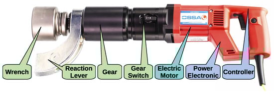
Figure 1.
Main subsystems of an electric torque tool for threaded connection tightening.
One of the most important components of an electromechanical electric torque tool is the electric motor. The two types of motors most commonly used in this type of equipment are a commutated series-wound universal motor powered by the AC power grid and a BLDC motor, either mains or battery-powered. This article focuses on the latter type of drive.
The issue of BLDC motor modeling is well described in the literature [3,4,5], and a relevant analysis along with a literature review is provided in Section 3. This article focuses on the selection of a motor model suitable for building a comprehensive multi-domain model of an electric torque tool and the joint tightening process. Four simulation models are considered, two taken from the Simscape Electrical toolbox of the MATLAB 2023b/Simulink environment, and two developed by the authors. They are presented in Section 4. The corresponding simulation studies of the considered models are described in detail in Section 5. The comparison is based on two types of criteria. The first group is related to the structure, flexibility, and implementation of the model, while the second category is connected with model fidelity—its ability to reproduce various physical phenomena that occur in the motor, e.g., cogging torque or permanent magnet demagnetization. In the presented application, some properties of the motor model are crucial, while other can be neglected. Therefore, the comparison criteria have been selected based on the specific characteristics of the analyzed system and its intended usage. Conclusions and final remarks are given in Section 6.
When selecting building blocks for a multi-domain overall simulation model of a complex, multi-component mechatronic system, one can either employ ready-made models from well-established libraries or, alternatively, develop custom ones from scratch. The former solution saves effort and shortens development time or time-to-market in case of commercial projects. Application of proven solutions reduces the risk of software bugs because the models are usually thoroughly tested and proven by scientific and engineering communities. Much less expertise is required to run out-of-the-box models compared to developing in-house solutions. Library models are designed to integrate seamlessly with other library components and to interact effectively with a pertinent solver or simulation software. Their universal nature allows for easy adaptation to various use cases. For commercial solutions, technical product support is usually available from the vendor, whereas for open-source packages, user community forums often serve as valuable sources of information and help. However, generic nature or ready-made one-size-fits-all models often means they lack specific features that are crucial for specialized use cases. On the other hand, custom-made in-house models can be tailored to a specific application and provide greater flexibility in capturing the system behavior. Since model developers have full understanding of the model structure and operation, they can easily modify, adjust, and extend it according to project requirements and assumptions made. The cost associated with model development can be offset by savings on licensing fees associated with proprietary software packages.
The main goal of the paper is to present an analysis and comparison of four simulation models of BLDC electric motors. Two of them belong to a commercial toolbox of the MATLAB/Simulink package while two other have been developed by the authors of the paper. All four models are described and presented together with their underlying assumptions and characteristics. They are evaluated in terms of specific requirements associated with modeling of the operation of an electric torque tool in various operating modes and conditions. Results of carefully designed simulation tests are presented to support the analysis. We highlight peculiarities and limitations of the off-the-shelf library models that may make them unsuitable for certain specific applications. We demonstrate how, with in-house models, one can overcome these restrictions and arrive at an alternative solution that meets special requirements. The paper concludes with insights and recommendations regarding the applicability of considered models to various tasks and simulation analyses.
2. Multi-Domain Model Concept of an Electric Power Tool
Advanced specialized electric torque tools play a critical role in precise tightening of threaded connections in numerous industries. They are widely used in applications including construction building, chemical reactor manufacturing and installation, petrochemical plant building, and wind turbine construction. These operations commonly involve large diameter bolts (above M30) that must be tightened with torque often exceeding 1000 N·m. Electric torque tools are engineered to deliver torque that can range from around 500 N·m to as high as 25,000 N·m, depending on their specific design. A block diagram in Figure 2 shows various subsystems that make up a typical electric torque tool.
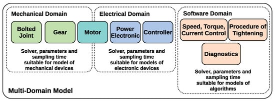
Figure 2.
The concept of a multi-domain simulation model of an electric torque tool, spanning mechanical, electrical, and software domains.
The device comprises the following components:
- An electric motor—usually a universal AC motor or a BLDC motor,
- An electronic controller,
- A mechanical gearbox, most often a two- or three-stage planetary gearbox with a ratio of up to several thousand,
- A gear selector, integrated with the transmission,
- A reaction arm to counteract torque reaction forces,
- An interchangeable working socket, matching a specific type of a nut or a bolt head.
The most common designs of electric torque tool controllers use simple linear algorithms to estimate the tightening torque based on the measurement of the motor current. These algorithms often do not provide adequate tightening accuracy. This is especially true at low engine speed. The use of two- or three-stage planetary gears with a very large gear ratio also negatively affects tightening accuracy. Such detrimental effects can be observed especially for very long bolts of high elasticity. The linear estimation algorithm is inaccurate in such cases and introduces significant errors. In addition, the energy stored in the elasticity of the bolt during the tightening process is rapidly released when the motor power is turned off, which can damage the gearbox of the electric torque tool. On the other hand, tightening a large number of screws with short threads in a row generally leads to rapid overheating of the device. The consequence of such situations is its damage and costly repair. In such cases, a good solution is to use modified estimation and tightening control algorithms, adapted to the specifics of the unusual screw connection or unusual operating conditions of the device.
Conducting experiments on actual bolted connections is very labor-intensive and expensive, and requires specialized test stands. Some experiments can lead to damage to the device under test or destruction of the bolted connection and can pose a risk to personnel. The use of a multi-domain model of the entire device along with a model of a specific type of bolted connection allows any new bolting algorithm to be tested relatively quickly and extensively in a simulation environment. In turn, the use of the Model-Based Design (MBD) technique allows the new algorithm to be quickly implemented into the physical device. The design and use of a multi-domain model can help reduce the cost and workload required to improve existing devices or create new versions of them.
Figure 2 shows a concept of a combined model of an electric torque tool and a bolted joint. The block diagram is divided into three simulation domains: the mechanical domain, the electrical domain, and the algorithmic domain. The mechanical domain includes the bolted connection, the gearbox, and the mechanical components of the motor. The electrical domain is made up of the motor electrical circuit, the power electronics circuit, and the microcontroller. The algorithmic domain includes control algorithms, procedures for managing the tightening process, and diagnostic algorithms.
Each domain requires the use of different types of models and simulation methods. Maintaining the proposed division of the model into individual components and applying the appropriate simulation tools enable relatively simple implementation of HIL (Hardware in the Loop) simulation techniques. This approach allows for rapid testing of new control algorithms using the target real-world microprocessor-based controller.
This study is devoted to the selection of a simulation model for the BLDC motor. The subsequent analysis aims to compare various models based on simulation results and to identify the most suitable one that meets the specific requirements of multi-domain modeling for the screwing process. To evaluate the quality of the BLDC motor models, key criteria have been adopted as follows:
- Ease of modification, editing, and extension, significant for adapting the model to various simulation scenarios, and related to the model structure and implementation details.
- Model fidelity and ability to reproduce various physical phenomena affecting the operation of the electric torque tool, like cogging torque, permanent magnet demagnetization, or custom non-standard back-EMF (electromotive force) profiles.
3. BLDC Motor Modeling
The BLDC motor mathematical models commonly presented in the literature are generally simplified, and the accuracy of their numerical solutions using available tools (e.g., MATLAB/Simulink) is rarely validated. This is particularly true for models designed for the synthesis of motor control systems [6,7]. The mathematical formulation of these models often does not allow for reliable simulation of the commutation processes in the machine, including the associated alternating components of the motor torque [8].
Typically, power losses in the magnetic circuit of the machine are ignored. In BLDC motors, these losses are usually dependent on the square of the current and result from phase leakage fluxes rather than the main flux of the machine [9]. Consequently, these losses can often be indirectly accounted for by increasing the phase resistances above their values measured with direct current.
Additionally, mutual inductances between phases are frequently neglected in the models [6,7]. It is also common to assume a perfectly trapezoidal waveform for the machine phase and interphase internal back-EMFs. The impact of the stator slotting on the time-varying profile of the generated torque is rarely considered. Similarly, the influence of temperature on the permanent magnet flux is often ignored, with the flux typically assumed to remain constant.
Cogging torques are also routinely excluded from these models. While a properly designed motor should minimize the cogging torque, in compact, high-speed BLDC motors used in electric torque tool, the ability to eliminate it through design is limited.
All the above-mentioned limitations of BLDC motor models apply to the study presented in [10]. The motor model employed for the synthesis of Field-Oriented Control (FOC) assumes the following simplifications:
- No mutual inductance between phases,
- No iron losses,
- Linear dependence of torque on instantaneous phase currents,
- Trapezoidal back-EMF profile,
- No cogging torque,
- Omission of commutation processes.
The authors of this work deemed this model sufficient for the synthesis of vector control for the motor, although the paper does not include experimental verification of the developed control system. In other studies on vector control synthesis for such motors (e.g., [11,12,13]), this type of model is commonly used, sometimes with the addition of mutual inductance between phases [12].
Similar model simplifications are present in the motor model used in a study that is not related to vector control synthesis [14]. An additional justification for employing a simplified motor model is the state-space form of its equations, which is convenient for the synthesis of speed and rotor position control. A similar model is used in many other studies that are not related to vector control, e.g., [15,16,17].
Authors focusing on developing control algorithms often intentionally adopt certain model simplifications. They assume that the controller is robust enough to handle errors resulting from the use of simplified motor models for parameter tuning. Approaches that make use of the automatic tuning of controller parameters are also frequently encountered. This methodology proves effective in many practical applications but may be insufficient in cases where omitted properties of the electric drive significantly impact the system precision and stability.
Model simplification is acceptable for typical, uncomplicated control scenarios where significant loads or rapid speed changes are not present. In such cases, reduced model fidelity does not critically affect the performance of the system. The limitations resulting from the motor model simplifications remain unnoticed, as the developed control algorithms are often tested only with motors operating without load or with laboratory loads, such as a DC generator.
In case of electric torque tool, simplifications of commonly used BLDC motor models become significantly important. Phase commutation of the motor generates alternating torques, which, through the gearbox, can negatively impact the threaded connection. The high gear ratio leads to the alternating component of the output torque reaching an unacceptable level. Furthermore, irregular waveforms of phase back-EMFs exacerbate these effects. Another critical issue is the reduction in magnetic flux of permanent magnets as the temperature increases, which results in a decrease in the tightening torque. The temperature rise is caused not only by power losses in the windings but also in the magnetic core, which is particularly noticeable at high rotational speeds, reaching up to 15,000 rpm. These phenomena, often neglected in standard models, should be taken into account in the context of electric torque tools. However, they are rarely addressed in the literature, and publications that account for them typically come from the field of electrical machines rather than automatic control (e.g., [18,19,20]).
Availability of a high-fidelity simulation model of an electric motor is crucial not only for design and evaluation of high-performant and advanced control methods for complex, multi-domain, multi-component mechatronic systems. An accurate model of a prime mover is equally important for development and validation of condition monitoring systems and algorithms for fault detection and classification. The problem is well understood in the field of diagnostics of popular and mass-produced asynchronous squirrel-cage induction motors (e.g., [21,22]), but it applies to BLDC motors as well.
The following subsections present two variants of a generic lumped-parameter mathematical model of a BLDC motor. The first set of equations is expressed in terms of three-phase currents and voltages, while the second uses two phase-to-phase voltages and corresponding phase current differences. Those two systems of equations lay the foundation for four simulation models presented, analyzed, and compared in the remaining sections of the paper.
3.1. Foundation Model
The most general and practically applicable mathematical model of a three-phase BLDC machine is described by the following set of equations [23]:
where
- —armature phase resistance,
- —self-inductance of a phase,
- —mutual inductance between phases,
- —angular speed of the rotor,
- —rotor position angle,
- J—rotor moment of inertia,
- —electromagnetic torque of the rotor with respect to the stator,
- —external mechanical load torque (),
- —armature phase magnetic flux linkages (excluding fluxes from the permanent magnets),
- —phase back-EMFs generated by permanent magnets, depending on the angular position of the rotor and its angular speed,
- —phase supply voltages,
- —armature phase currents.
When formulating the model, assumptions were made as follows:
- Full internal symmetry of the machine, both electrical and magnetic, is assumed. All phase windings are constructed identically, as are the rotor excitation poles, and the rotor is centrally positioned relative to the stator. This assumption is practically satisfied.
- Linearity of the magnetic circuit magnetization. This allows for the use of constant values for self-inductance and mutual inductance of the phases. This assumption can be considered valid due to the presence of neodymium magnets in the machine magnetic circuit.
- Absence of armature slotting. That assumption eliminates the cogging torque. However, if the cogging torque profile as a function of rotor position is known (from FEM calculations or measurements on a real machine), it can be included in Equation (4) as yet another term of the numerator on the right-hand side.
- Constant value of the rotor moment of inertia.
- The model does not consider thermal phenomena, such as changes in the phase resistance of the armature or variations in the phase back-EMF values due to temperature.
- Neglecting potential mechanical deformations of the motor structure during operation.
3.2. Differential Model
The model presented in the previous subsection requires knowledge of phase supply voltages. However, it can be reformulated so that the inputs are two phase-to-phase voltages. To achieve this, Equations (1) and (2), as well as (2) and (3), must be subtracted. As a result, the armature of the machine can be described using only two differential equations, with variables in the form of current differences and , related to the differential fluxes and , and line voltages and as input quantities. The need for this reformulation arises from the three-wire supply of the motor via a six-transistor bridge.
The resulting equations for a linear model of a BLDC motor, wye-connected and three-wire supplied, written using differential currents, voltages, and back-EMFs, are given below:
where
- —phase resistance,
- —phase self-inductance,
- —mutual inductance between phases a and b, ,
- —mutual inductance between phases b and c, ,
- —mutual inductance between phases a and c, ,
- —rotor angular speed,
- —rotor position angle,
- J—rotor moment of inertia,
- —electromagnetic torque of the machine,
- —external torque acting on the shaft (negative for load),
- —magnetic fluxes linked with the armature phases (excluding fluxes from magnets),
- —differences of flux linkages of phases a and b or b and c, respectively,
- —phase back-EMFs from permanent magnets, depending on the angular position of the rotor and its angular speed,
- —line back-EMFs (phase-to-phase),
- —phase supply voltages,
- —line supply voltages (phase-to-phase),
- —phase currents,
- —differences of phase currents of the motor.
This model is developed under the assumption that , , , and , which is justified by the lack of salient poles in a typical BLDC machine with surface-mounted permanent magnets. Thus, the model does not capture the potential reluctance torques of the machine. The model also neglects the cogging torque (), but if it is known as a function of rotor position (from measurements or FEM calculations), it can be added to the torque sum in (10).
4. Simulation Models
In this section, a description of four selected BLDC motor simulation models is presented. They include two ready-to-use single-block models available in the Simscape Electrical toolbox of the MATLAB/Simulink package, as well as further two custom (in-house) models developed by the authors. All the models are compatible with the MATLAB/Simulink environment. They differ in terms of toolboxes (libraries) used, implemented equations, and underlying assumptions. Special attention is paid to the modeling assumptions, applied simulation techniques, and simulation parameters that affect the accuracy and representation of the dynamic behavior of electric machines. For the benefit of the reader and to ensure clarity throughout the subsequent model descriptions, all variables and abbreviations used are explained each time they appear.
The MATLAB/Simulink package is a commercial, well-established, widespread, and popular tool used by engineers and scientists in academia and industry for research and development purposes. It can find its applications in various fields, including electromechanical system modeling and control algorithm development, thanks to numerous toolboxes (libraries) that extend its capabilities. That makes the MATLAB/Simulink environment an attractive choice for multi-domain system modeling, analysis, and design. Models available in MATLAB toolboxes come with an extensive documentation and relevant literature references. That makes the BLDC machine models from the Simscape Electrical library a natural choice for our research and a reliable reference base for model comparison presented in the paper.
The universal nature of ready-to-use simulation models from the library can make them less suitable for some specific applications, like electric torque tool modeling considered in Section 2. That prompted the authors do develop two in-house models, introduced further in this section, to address some use case-specific requirements. All four models will be compared based on results of carefully designed simulation tests with a set of relevant criteria. This will enable us to formulate recommendations regarding their selection and use, and to determine when ready-made models are appropriate and when custom-made solutions should be employed instead.
4.1. Model 1 (Specialized Power Systems)
The first considered model is implemented as a Permanent Magnet Synchronous Machine block in the Electrical Machines folder of the Simscape/Electrical/Specialized Power Systems blockset of the MATLAB/Simulink application. The stator windings are connected in a star configuration with an internal neutral point. The library block is labeled by default as a “Permanent Magnet Synchronous Machine”, but it can represent a BLDC machine as well, provided that a trapezoidal back-EMF profile is selected. According to the manufacturer’s documentation, the three-phase model can support either a sinusoidal or a trapezoidal back-EMF waveform. The Permanent Magnet Synchronous Machine block can operate in generator or motor mode, depending on the sign of the mechanical torque (positive for motor operation, negative for generator operation). The electrical and mechanical components are modeled using second-order state space equations.
The key assumptions of the model include the following:
- Linearity of the magnetization characteristic throughout the entire magnetic circuit of the machine.
- Iron losses are not considered in the model.
- The variability of self and mutual inductances of the stator phases is described by sinusoidal functions of the rotor angular position, which is characteristic of alternating current (AC) brushless machines. For direct current (DC) brushless machines, the inductances remain constant regardless of the rotor position.
- The model assumes the star connection of the stator phases, which is a limitation of the model.
- The model does not allow for the modeling of cogging torque.
The model is described by the following equations:
where
- —resistance of the stator windings,
- —inductance of the stator windings,
- —angular speed of the rotor,
- —angular position of the rotor,
- J—rotor moment of inertia,
- —electromagnetic torque,
- —load torque of the motor,
- —a, b, and c phase back-EMFs, in per-unit value with respect to the amplitude of the flux ,
- —ab and bc phase-to-phase voltages,
- —a, b, and c phase currents,
- —amplitude of the flux induced by the permanent magnets of the rotor in the stator phases,
- p—number of pole pairs.
According to MATLAB documentation [24], the model is based on [25,26,27].
4.2. Model 2 (Simscape Electrical)
The second considered model is available as a BLDC block in the Electromechanical/Permanent Magnet folder of the Simscape/Electrical blockset of the MATLAB/Simulink application. The BLDC model simulates a BLDC machine with a three-phase stator winding, which can be connected in either a star or delta configuration. This block can be used for modeling both standard BLDC motors and BLDC servo motors.
The key features of the model are as follows:
- The model is based on the assumption of linearity in the magnetization process throughout the entire magnetic circuit of the machine.
- Self and mutual inductances of the armature (stator) are assumed to vary sinusoidally with the rotor position.
- The phase back-EMFs generated by the magnets are assumed to vary trapezoidally as a function of rotor position (with the option to apply a different waveform defined with tabulated data).
- The phase back-EMFs are not restricted to a specific stator phase connection, meaning they are suitable for both star and delta configurations.
- The model is expressed in the 0 dq coordinate system.
- Iron losses can be included in the model. However, the available approach is simplified and incomplete, as it is valid only for sinusoidal voltage waveforms under steady-state conditions. This limits its accuracy under more dynamic conditions.
The following equations describe the model in the Park coordinate system:
where
- —phase resistance,
- —self-inductance of the phase,
- —mutual inductance of phases,
- —angular speed of the rotor,
- —angular position of the rotor,
- —electromagnetic torque generated by the motor,
- —load torque,
- p—the number of rotor permanent magnet pole pairs,
- —electrical angular position of the rotor,
- P—the Park transformation matrix:
- , , and —partial derivatives of instantaneous permanent magnet flux linkages of individual phases of the winding, with respect to electrical or mechanical angle,
- , , and —d-axis, q-axis, and zero-sequence voltages,
- , , and —d-axis, q-axis, and zero-sequence currents, defined by
- —stator d-axis inductance,
- —stator q-axis inductance,
- —stator zero-sequence inductance,
- —amplitude of changes in the phase self-inductance with the rotor position angle.
According to MATLAB documentation [28], the model has been created based on [29,30,31].
4.3. Model 3 (Custom Differential)
The third considered model has been developed by the authors at AGH University. It is implemented as a Simulink subsystem presented in Figure 3 and it is based on Equations (8)–(17). Unlike other three considered models, it is fed with phase-to-phase rather than phase-to-neutral voltages.
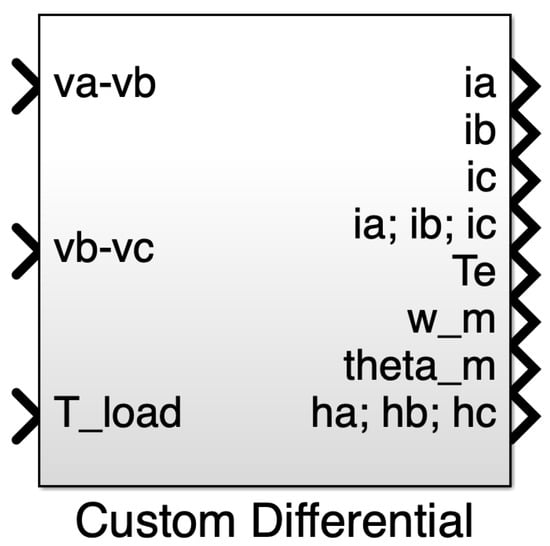
Figure 3.
Block symbol of Model 3 (Custom Differential). It is an in-house model developed by the authors. The model is expressed in terms of phase-to-phase voltages and differences of phase currents and phase flux linkages. It is built with standard Simulink blocks—the Simscape toolbox is not required.
The key assumptions of the model are as follows:
- The model assumes the star connection of the stator phases, which is one of its limitations.
- The machine is powered by line voltages, implemented through an appropriate transformation of voltage equations.
- The electromagnetic torque is calculated with consideration of the alternating components and harmonic content of the phase back-EMFs.
- Cogging torque can be included in the model provided that measurement or FEM simulation results are available.
- The model accurately replicates commutation by separately modeling the self-inductances and mutual inductances of individual phases.
- Power losses are modeled as load-dependent losses, proportional to the square of the root mean square (RMS) phase currents, by increasing the phase resistances.
Unlike three other models considered in the paper, this one does not leverage a physical modeling approach. Hence, it cannot be integrated directly with commutation bridge models built with blocks available in the Simscape Electrical library. Instead, a dedicated compatible bridge and commutator model has been prepared using standard Simulink blocks. It comprises three switches which select output bridge voltages based on current zero crossing events. A higher fidelity model of a power transistor will be considered at a later stage, along with the inclusion of other elements of the power electronics system.
The inclusion of separate self-inductances and mutual inductances of the phases allows for an accurate representation of the commutation process (excluding the power electronics system), which is particularly critical in high-speed machines where the commutation time constitutes a significant fraction of the total phase conduction time.
4.4. Model 4 (Custom Simscape)
The fourth considered model has been developed at AGH by the authors. Its graphical symbol is presented in Figure 4. The model allows for mutual inductance modeling and incorporation of real back-EMF profiles. Thanks to these features, it has been successfully used to investigate and explain the speed–frequency locking phenomenon [32].
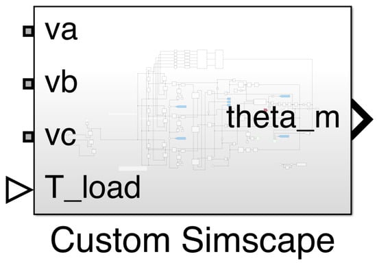
Figure 4.
Block symbol of Model 4 (Custom Simscape). It is an in-house model developed by the authors. The model is built with blocks from the Simscape toolbox; however, the Simscape Electrical library is not required.
Model 4 (Custom Simscape) was developed based on the following equations, which are a generalized version of (1)–(7):
where
- , , —resistances of individual armature winding phases,
- , , —self-inductances of stator winding phases,
- , , —mutual inductances of phases of the stator winding,
- —angular speed of the rotor,
- —rotor angular position,
- —rotor electrical angular position,
- J—the motor rotor moment of inertia,
- —electromagnetic torque generated by the motor,
- —load torque,
- , , —back-EMFs of individual phases corresponding to unit angular speed of the rotor, depending on its angular position,
- —phase supply voltages,
- , , —electrical currents of individual phases of a wye-wound stator winding,
- p—number of rotor pole pairs.
The simulation model leverages the physical modeling approach supported by Simulink and Simscape. It is built with blocks from the Foundation Library of the Simscape toolbox. Motor windings are represented by a physical network made of Resistor and Mutual Inductor blocks. They belong to the electrical domain—one of many supported by Simscape. The topology of the electrical circuit corresponds directly to the first three (electrical) equations of the motor model.
The back-EMFs of the phase windings are represented by Controlled Voltage Sources. Each voltage source is fed with a physical signal computed as a product of the angular velocity of the motor shaft and the back-EMF voltage per unit speed. The latter is computed by PS Lookup Table blocks, based on a provided profile and the angular position of the shaft (wrapped with the modulo operation). Phase currents signals are provided by Current Sensor blocks. The currents are used for computation of the electromagnetic torque produced by the motor. A model of a mechanical part of the motor is relatively simple. It has been implemented with a few blocks operating on physical signals and implementing addition, scaling, and integration operations. A cascade of two integrators fed with the angular acceleration computes angular velocity and position of the motor shaft. The acceleration depends on the difference between electromagnetic and load torques.
Despite the apparent complexity of the Simulink model, its structure is self-explanatory as it corresponds closely to the original set of equations describing the system. Hence, the diagram can be easily understood and modified or extended to model further phenomena or improve fidelity of the model. Since each phase is represented by a (partially) independent subset of model components, it is relatively easy to model asymmetry or unbalance in phase properties (e.g., different inductances or back-EMF profiles). On the other hand, the Mutual Inductor block from the library does not allow modeling of either inductance nonlinearity or its dependence on the rotor position. The model uses components of the Simscape toolbox. However, the Foundation Library alone is sufficient and no add-on products like Simscape Electrical are required.
Key assumptions of the model are as follows:
- The back-EMFs induced in the phase windings are represented by Controlled Voltage Sources fed with signals from Look-Up Table blocks. Hence, the model can support arbitrary back-EMFs profiles, including those acquired experimentally or computed using the FEM analysis method.
- The simulation of the armature windings is based on a linear magnetic model (inductances do not depend on currents).
- Iron losses are not considered.
- The Mutual Inductor block does not allow modeling of the inductance dependence on the rotor angular position. Hence, the reluctance torque cannot be simulated.
- Due to the fact that each phase is represented by a (partially) independent subset of model components, it is relatively easy to model phase asymmetries, such as different inductances or induced voltage profiles.
- The model can be easily extended to account for the cogging torque, if relevant experimental data are available.
5. Model Comparison
To evaluate the four BLDC motor simulation models described in the previous section, some simulation tests have been designed and conducted. The goal was to assess the suitability of the models for multi-domain modeling and their applicability within the MBD methodology for MIL (Model-in-the-Loop), HIL (Hardware-in-the-Loop), and RCP (Rapid Control Prototyping) testing with automatic code generation. The following criteria were used for model evaluation:
- Modifiability and extensibility of the model; its openness. (Can the user easily alter the structure of the model, add some new features, and change the model behavior?)
- Ease of integration with the Simscape toolbox. (Can the model be easily and directly connected to a physical network made of Simscape library components representing electrical and mechanical domains?)
- Real back-EMF profile implementation capability. (Can the user freely define the phase back-EMF profile? Does the model accept tabulated data obtained from experimental measurements? Is it possible to assign distinct profiles to individual phases?)
- Permanent magnet demagnetization modeling capability. (Can we model a gradual progressive demagnetization process? Can these changes be applied at runtime?)
- Resistive electric braking modeling capability. (Does the machine model support both motoring and generating modes of operation? Can it represent bidirectional transformation of electrical and mechanical power? Is it possible to integrate a braking resistor with the drive model?)
- Cogging torque modeling capability. (Is it possible to feed the model with an experimentally determined tabulated cogging torque profile?)
To ensure a consistent comparison, all four Simulink models prepared for the simulation tests share an identical structure, as shown in Figure 5. The core of the Simulink test model consists of a motor integrated with a three-phase power bridge, Hall-effect position sensors, an electronic commutator controller, and a resistor with a switch for rheostatic dynamic braking. A test harness comprises two additional blocks. The first one implements a test scenario by controlling the mode of operation of the drive system and generating supply voltage and mechanical load profiles. The other subsystem is responsible for measurements, auxiliary calculations, and data logging.
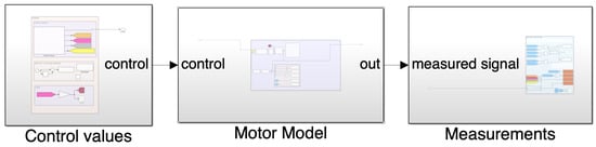
Figure 5.
Simulink model that was a test harness for all the models. The ‘Control Values’ subsystem implements a test scenario and generates signals controlling and affecting the simulated drive: power bridge supply voltage profile (for soft-start implementation), dynamic braking flag (for controlling braking resistor switch), and load torque profile. The ‘Motor Model’ subsystem comprises simulation models of the BLDC motor, three Hall-effect switches for commutation control, and a three-phase power bridge integrated with a resistor and a switch for rheostatic dynamic braking. The ‘Measurements’ subsystem is responsible for simulation data processing (instantaneous power computation) and logging.
The purpose of this study was to analyze the behavior of these models under simulation conditions that reflect the real operating conditions of an electric torque tool. To determine typical working conditions for the motor, data from real bolt joint tightening processes were used and analyzed. Figure 6 presents typical time series of torque, speed, and motor current encountered in a single cycle of a power torque tool operation. This example tightening process was performed using a SETT tool manufactured by OSSA Machinery Works, Tychy, Poland, capable of recording key operating parameters. This particular tool is powered by a universal motor, features a three-stage planetary gearbox with a reduction ratio of approximately 4000:1, and enables tightening with a torque of up to 2800 N·m. The chart in Figure 6 shows profiles of the following:
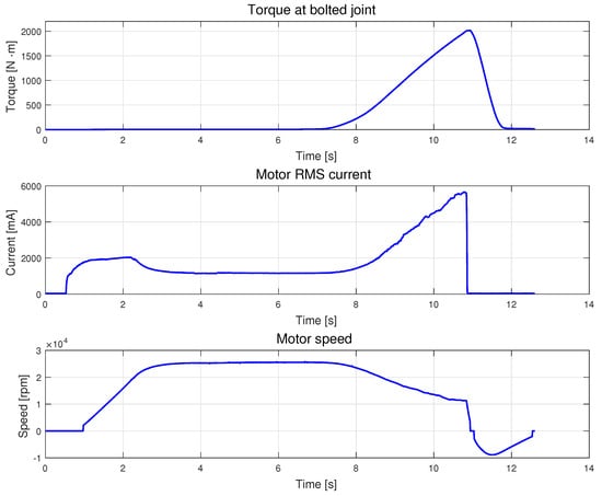
Figure 6.
Screw connection torque, motor rotational speed, and motor RMS current profiles corresponding to a typical bolted joint tightening process. Data acquired experimentally with a commercial electric torque tool.
- Tightening torque at the bolted joint,
- Motor RMS current,
- Motor rotor rotational speed.
The torque measurement was performed directly on the bolted joint using a specialized torque sensor [33]. The RMS motor current was measured and computed directly by the motor controller. The instantaneous current value was sampled 100 times during a single power grid half-period, and the RMS value was calculated according to its definition. The rotational speed of the motor rotor was also measured directly by the motor controller.
Based on the recorded waveforms, four typical operating stages of the tightening process were identified, including the following:
- Startup: Initiation and acceleration in a soft-start mode. During that stage, the controller ramps the RMS voltage applied to the motor. The loose screw joint exhibits relatively low friction torque.
- Idle operation: Free rotation of the nut. Low friction torque is observed, while the rotational speed remains steady.
- Load increase: The actual tightening process. The increasing tension in the bolt enhances friction between the nut, bolt, and washer, resulting in a gradual reduction in motor speed.
- Control deactivation: Slowing down and stopping the motor using resistive braking. That stage is initiated as soon as the electric torque tool controller detects that the desired torque level has been reached.
For the loosening or disassembling process, three characteristic stages were identified as follows:
- Rapid torque increase. The tightened bolted joint resists the unfastening process.
- Rapid torque decrease. As the bolted connection loosens, the tension in the bolt decreases, leading to a significant reduction in friction.
- Idle operation: Rotation of a loose nut. The friction torque at the joint is approximately constant and relatively low, resulting in nearly constant and high motor speed.
An analysis of the bolt loosening process highlights a transitional state between high motor load (typical for actual loosening) and idle operation (turning a free nut). The values and rates of torque increase depend on the specifics of the bolted joint and the type of torque tool used. Sudden changes in torque, both increases and decreases, can be simplified and represented by step changes approximating actual torque profiles.
For the sake of combined simulation of tightening and undoing processes, four operating modes have been defined as follows:
- MODE 1: Startup and subsequent idle operation. This mode includes a soft-start implementation, achieved by gradually increasing the motor supply voltage from zero up to the full rated value.
- MODE 2: Step-applied load and subsequent operation under load. The load is applied to the motor in a step-like manner, which in practice corresponds to tightening a bolt until it begins to resist.
- MODE 3: Step-removed load. The load is removed from the motor in a step-like manner, which in practice corresponds to loosening a bolt.
- MODE 4: Stop with the use of electrical braking. After loosening the bolt, the controller activates electrical braking to dissipate the kinetic energy stored in the motor and the gearbox.
The four BLDC motor models presented in Section 4 differ in parametrization flexibility and level of detail and, consequently, modeling fidelity. Two types of simulation test have been conducted to compare them. For the first stage, all models have been parametrized in a consistent way to verify if they are able to provide equivalent responses. For the second stage, each model has been parameterized individually to achieve the highest possible level of fidelity it can provide. The most detailed and flexible model has been selected as a reference for comparison. The objectives of these two stages of simulation tests were as follows:
- Stage 1: The goal of the first stage was to verify whether, under identical experimental conditions and for equivalent motor parameters, the models generate comparable profiles of speed, phase currents, and torque, while neglecting mechanical losses.
- Stage 2: The goal of the second stage was to configure each model with settings that reflect real-world conditions as closely as possible. In particular, each model has been fed with a back-EMF profile as close to the real one as the model structure permits. These experiments accounted for the limitations arising from the structure of the models and the functionalities available in each case.
This staged approach was encouraged by preliminary tests, which revealed non-negligible discrepancies in the generated results. Analysis of the models helped identify the causes of these differences. One of the models–Model 1 (Specialized Power Systems)–simulates the trapezoidal back-EMF profile with a sine waveform clipped at , which leads to noticeable deviations compared to results obtained with the other models. Figure 7 shows the way the back-EMF profile is computed in the model, while Figure 8 presents an example of a resulting clipped sinusoidal waveform approximating a trapezoidal profile. This specific back-EMF profile was applied to all models for the first stage of simulation tests to provide consistent comparison conditions.
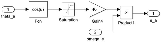
Figure 7.
The method of simulation of the back-EMF of phase a in the Permanent Magnet Synchronous Machine library model when the trapezoidal back-EMF waveform is selected. To form a pseudo-trapezoidal profile, the cosine waveform is clipped at the top and bottom, then scaled and multiplied by the electrical angular speed.
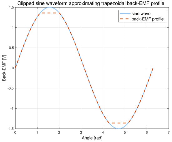
Figure 8.
An example waveform of the back-EMF generated by the Permanent Magnet Synchronous Machine model subsystem, when the Trapezoidal option for the Back EMF waveform parameter is selected.
For both comparison stages, all remaining parameters of the models were standardized. However, for the first stage, the models were unified to the maximum extent possible. This meant that all models were aligned with the simplest model, and parameters not supported by the simplest model were omitted in the others. For the second stage, on the other hand, the goal was to achieve the best performance each model can provide by making use of all parameters it supports. The parameters used for simulations correspond to the METABO 317004610 electric BLDC motor, manufactured by Metabowerke GmbH, Nürtingen, Germany. They have been estimated based on results of several identification tests. Motor parameters and properties are given in Table 1.

Table 1.
Technical parameters and properties of the electric permanent magnet BLDC motor used in the simulation models.
However, it was not possible to standardize all settings, especially in case of numerical solvers employed for simulation. In case of Simulink models that make use of blocks from both Simscape and standard Simulink blocksets, two solvers are engaged. The solvers used in the analysis of considered models are as follows:
- Model 1 (Specialized Power Systems):
- –
- Simulink–ode4 (Runge–Kutta)
- –
- Specialized Power Systems–Continuous (selected in the powergui block)
- Model 2 (Simscape Electrical):
- –
- Simulink–odeN (Nonadaptive)
- –
- Simscape–Backward Euler
- Model 3 (Custom Differential):
- –
- Simulink–ode4 (Runge–Kutta)
- Model 4 (Custom Simscape):
- –
- Simulink–odeN (Nonadaptive)
- –
- Simscape–Backward Euler
Figure 9 presents results of the first stage of simulation tests, where all models were provided with the back-EMF profile compatible with Model 1 (Specialized Power Systems), implemented as the Permanent Magnet Synchronous Machine library block. Four modes of operation have been applied in a sequence: soft-start, stepwise load application and removal, and dynamic braking. The computed responses of considered models differ slightly, but the difference does not exceed 1.5%.
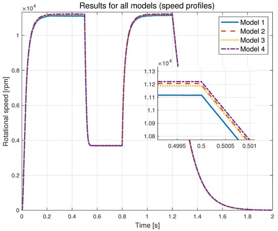
Figure 9.
The simulation results for all four models: Model 1 (Specialized Power Systems), Model 2 (Simscape Electrical), Model 3 (Custom Differential), and Model 4 (Custom Simscape). All models use identical back-EMF profile corresponding to a clipped sine wave implemented in the Permanent Magnet Synchronous Machine block from the Simscape Electrical–Specialized Power Systems library.
After confirming that application of identical parameters to all models results in nearly identical behavior, the second stage of simulation testing was initiated. The goal of this stage was to achieve the highest possible modeling fidelity for each model.
For all models except Model 1 (Specialized Power Systems), a tabulated back-EMF profile was applied, corresponding to the one recorded during identification experiments with the real motor using a digital storage oscilloscope. Since Model 1 (Specialized Power Systems) does not allow for the introduction of an arbitrary back-EMF profile, it was fed with the parameters of a pseudo-trapezoidal profile approximating the experimental waveform. Both profiles—the recorded one and the fitted clipped sinusoidal function, that is the core function for back-EMF for Model 1 (Specialized Power Systems)—are shown in Figure 10. The simulation results, in which each model was provided with the most accurate back-EMF profile that it supports, are presented in Figure 11. One can notice a considerable difference in the steady state speed between Model 1 (Specialized Power Systems) and the other three models. It results mainly from the inability of the first model to represent an exact profile of the phase back-EMF. The differences in steady state speed between the other three models are negligible.
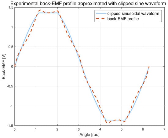
Figure 10.
Experimentally determined back-EMF profile, corresponding to the rotational speed of 3000 rpm, approximated with a clipped sine waveform. The approximation is necessary since Model 1 (Specialized Power Systems) does not support tabulated EMF profiles.
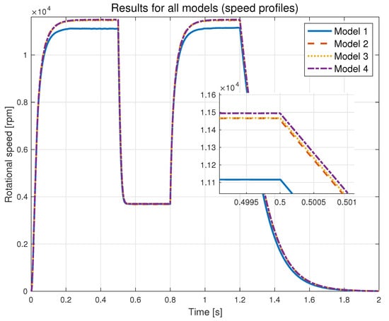
Figure 11.
The simulation results of all four models: Model 1 (Specialized Power Systems), Model 2 (Simscape Electrical), Model 3 (Custom Differential), and Model 4 (Custom Simscape). For each model, the applied back-EMF profile is as close to the actual (experimental) one as the model permits.
For the purpose of comparing the models in terms of multi-domain modeling, their most important properties are gathered in Table 2. The method of selecting the criteria is described in Section 2. A five-level Likert scale has been used for evaluation. To rate individual models using the defined criteria, questions constructed according to a common template were used, e.g., “How do you evaluate the capability of modeling the cogging torque for a given model?” The Likert scale levels are defined as follows: 1—very bad, 2—bad, 3—neutral, 4—good, and 5—very good. Specifically, for the first criterion in the table, ‘Modifiability and Extensibility’, level 4 indicates a fully open simulation model that can be freely modified or extended by the user. That applies to the two custom-made models presented in the paper. Level 3 is assigned to a ready-made library block that can only be viewed and modified after disabling and breaking a library link that makes the block read-only. That applies to Model 1 (Specialized Power System). Level 1 corresponds to a closed proprietary library block that does not allow any modification by the user and does not expose the underlying source code. It is the case of Model 2 (Simscape Electrical). The highest score of 5 has not been awarded since even the open models require some understanding and modeling skills from the user. In case of the second criterion, ‘Ease of Simscape Integration’, level 5 is assigned to a block belonging to the Simscape Electrical library (Model 2) that is fully compatible with the Simscape environment and to a custom model made of blocks originating from the Simscape Foundation Library (Model 4) that are natively supported by the Simscape solver. Level 3 is granted to a custom model made of standard Simulink library blocks (Model 3) that can be integrated with a Simscape network using PS-Simulink Converter and Simulink-PS Converter utility blocks. Level 2 marks a block from the Specialised Power System library (Model 1) that requires Current–Voltage Simscape Interface or Voltage–Current Simscape Interface blocks for Simscape integration. The internal structure and operation of the interface blocks is quite complex, since they make use of current and voltage sensor or measurement blocks, controlled voltage and current source blocks, Simulink-to-PS and PS-to-Simulink signal conversion blocks, and signal filtering blocks. Several types of signals and connections are used and several solvers are involved, which may deteriorate model performance and affect simulation results. For the third criterion, ‘Real Back-EMF Implementation Capability’, grade 5 indicates custom or standard library models that can accept an arbitrary back-EMF profile provided in a tabulated form (Models 2, 3, and 4). Level 2 is assigned to a library block that supports only two possible waveforms: sinusoidal and clipped sinusoidal (Model 1). For the fourth criterion, ‘Permanent Magnet Demagnetization Modeling Capability’, level 4 is granted for both the custom models (3 and 4), since they both allow for definition of different back-EMF profiles of individual phases. Hence, one can model a case with individual permanent magnets demagnetized to different degrees. The solution does not deserve the highest score of 5, since it does not allow for runtime changes and the demagnetization effect must be represented indirectly by back-EMF profile modification. Level 3 is awarded to a Simscape library block (Model 2) that supports an arbitrary back-EMF profile but the same profile is applied to all phases and no runtime changes are allowed. Level 2 is assigned to a Specialised Power System library block (Models 1) that supports only two possible back-EMF waveforms. They are identical for all phases, and no runtime changes are possible. For the fifth criterion, ‘Resistive Electric Braking Modelling Capability’, all models under comparison are awarded level 4, since they all cover both motor and generator operating modes of an electric machine. Finally, for the last, sixth criterion, ‘Cogging Torque Modeling Capability’, we assign mark 4 to both custom models (3 and 4) since they can be easily extended to account for the cogging torque, provided that its profile is available in a tabulated form or as a closed mathematical formula. A slightly lower level of 3 is awarded to a block from the Specialized Power System library (Model 1) since some preliminary steps have to be taken to allow the user to modify the block. The lowest score of 1 is granted for a block from the Simscape Electrical library (Model 2) because it is a read-only closed solution. The cogging torque support can still be added, but it cannot be achieved in a straightforward way.
Table 2.
Comparative analysis of different model implementations based on key evaluation criteria. A five-level Likert scale is used for rating.
6. Conclusions
Based on the comparative analysis presented in the preceding sections, conclusions can be formulated as follows:
- Model 1 (Specialized Power Systems), which is based on the Permanent Magnet Synchronous Machine block from the Simscape Electrical–Specialized Power Systems library, does not allow the use of custom or advanced back-EMF profiles (e.g., those significantly deviating from trapezoidal or sinusoidal waveforms). This limitation can lead to inaccuracies, particularly in small motors where the actual back-EMF form often deviates from the idealized shape. In contrast, the other three considered models accept back-EMF profiles in a tabular format, allowing for better alignment with real-world measurements. This capability ensures that irregular back-EMF shapes, arising from specific motor designs or magnet configurations, can be accurately captured in simulations.
- All four models can be effectively used for designing typical cascaded control systems for current and speed regulation. In such scenarios, the average electromagnetic torque and peak phase currents are the key considerations, making the details of commutation effects or higher harmonics of torque less critical. However, these detailed effects may become significant in applications requiring high acceleration or precise torque control, especially at very low or very high speeds.
- All evaluated models allow for the inclusion of demagnetization effects by modifying the back-EMF profile (e.g., by reducing the amplitude of the tabulated back-EMF). However, such modifications cannot be performed during simulation. Consequently, as follows:
- Modeling gradual degradation of motor parameters (e.g., due to long-term use or operation at high temperatures) is challenging and requires restarting the simulation with updated back-EMF parameters.
- Simulating rapid demagnetization events (e.g., caused by overheating beyond the Curie temperature) is not feasible.
- Only custom models enable modeling of partial demagnetization of individual magnets (and therefore specific phases) by introducing asymmetric back-EMF profiles and varying phase inductances, both self and mutual.
It is worth noting that Model 3 (Custom Differential) can be easily modified to enable the back-EMF profile to be changed during simulation. This can be achieved by replacing 1-D Lookup Table blocks with Lookup Table Dynamic components. Similar approach can be applied to Model 4 (Custom Simscape); however, in that case, it is necessary to replace a few blocks operating on physical signals with their counterparts from the standard Simulink library. - Of the the four models presented, only Model 2 (Simscape Electrical) enables direct modeling of thermal phenomena. All three other models do not account for motor heating over time or its impact on phase resistance and permanent magnet properties. Hence, changes in magnetic parameters (e.g., flux weakening at elevated temperatures) can only be implemented manually by modifying the back-EMF profile and restarting the simulation. In applications where temperatures may exceed 100°C (e.g., during prolonged high-speed operation), neglecting these effects can lead to inaccuracies. Incorporating thermal models into future work could address these limitations.
- All the compared models support analysis of various braking methods, including dynamic resistive braking (e.g., through appropriate inverter control).
- In small motors with a low number of rotor slots, cogging torque can reach up to 15% of the rated torque, significantly affecting control precision in certain applications.
- Both custom models allow for the inclusion of additional cogging torque component, provided as a tabulated function of the rotor position.
- Neither of the two library models supports such modifications in its standard configuration.
- Among the analyzed models, only Model 2 (Simscape Electrical) explicitly accounts for iron losses. However, implementation details are unclear—the documentation does not explain their effect on electrical equations of the motor. Iron losses can become particularly significant at high rotational speed and commutation frequency. Although it is possible to partially approximate such losses by increasing phase resistances, this method provides only a rough estimation.
- All models except Model 2 (Simscape Electrical) assume a linear magnetization characteristic of the magnetic circuit. This assumption is generally considered valid for modern motors equipped with neodymium magnets, as these machines typically operate well below magnetic saturation points.
- Presented models differ in number of Simulink blocksets they use. Since MATLAB/Simulink is a commercial software package, these alternative approaches incur different costs. Moreover, to work with a particular model, the researcher has to master toolboxes it involves. To run Model 3 (Custom Differential), the basic MATLAB/Simulink package is sufficient. For Model 4 (Custom Simscape), the Simscape library is required as well. Model 1 (Specialized Power Systems) and Model 2 (Simscape Electrical) additionally use the Simscape Electrical library.
In summary, for applications requiring high fidelity in capturing commutation effects, irregular back-EMF shapes, or cogging torque, the two custom models are the most flexible and suitable choices. These models, tailored to the application, provide a better representation of phenomena specific to small BLDC motors, making them particularly valuable in scenarios such as threaded joint tightening or high-speed device operation. However, if the primary goal is to design and test typical current and speed controllers, all four models can be used effectively with appropriate parameterization.
Beyond the technical capabilities, the choice of a model is also dictated by practical aspects such as software licensing costs and the user expertise required. The two ready-to-use single-block library models are based on the commercial Simscape Electrical toolbox, representing the highest cost. In contrast, Model 4 (Custom Simscape) requires only the Simscape Foundation Library, while Model 3 (Custom Differential) is the most cost-effective, being implementable with only the standard MATLAB/Simulink package.
All four simulation models considered in the paper are based on analytical lumped-parameter models derived from Kirchhoff’s voltage and current laws, fundamental electromagnetic relationships, and simplified magnetic circuit theory. Compared to resource-intensive numerical models based on the FEM method, they are computationally efficient, which makes them suitable for repeated simulations and multidimensional parameter sweep tests. Parameters of such models are easily explainable and relatively easy to determine experimentally with some standard tests, like direct DC winding resistance measurement, a decay test for winding inductance estimation, a coast-down test for mechanical friction determination, back-EMF profile recording, or cogging torque versus rotor position measurement. Alternatively, parameters of a lumped-parameter model can be estimated with magneto-static FEM analysis, if the motor geometry and material properties are known. That approach is especially convenient during the development phase, when the motor size, geometry, and structure are to be selected and decided. As an alternative to analytical or FEM-based models, one can follow the data-driven development paradigm and employ Machine Learning (ML) techniques to develop a simulation model of a motor. That approach requires, for training purposes, a large and diverse experimental data collection representing various operating conditions. Acquisition and preparation of a representative data set is not an easy task and there is always a risk of poor model behavior for cases that are missing from or underrepresented in the collection. This is especially true if various fault modes or abnormal operating conditions are to be simulated. In such cases, preparation of a rich enough training data set is quite impractical, expensive, time consuming, not always feasible, and for large high-power motors poses some risk to the engineering staff involved in the process. Hence, even today, in the era of ubiquitous data-driven machine learning solutions, there is still some room left for analytical lumped-parameter models applications.
Future work of the authors will focus on extending the discussed in-house models to include thermal effects, iron losses, and dynamic demagnetization phenomena. This will further enhance their applicability and accuracy in real-world scenarios. Additionally, the authors plan to develop a model of a planetary gear system, with particular emphasis on gear flexibility. Integrating the gearbox model with the motor model will enable a more comprehensive simulation of electromechanical interactions between subsystems of an electric torque tool.
Author Contributions
Conceptualization, P.P. and T.D.; methodology, T.D., A.T., P.K. and P.P.; software, P.K., A.T. and T.D.; validation, P.K., A.T. and T.D.; formal analysis, A.T.; investigation, T.D., A.T., P.K. and P.P.; resources, P.K.; data curation, P.K.; writing—original draft preparation, P.P., P.K., T.D. and A.T.; writing—review and editing, P.K., T.D. and A.T.; visualization, P.K.; supervision, P.P.; project administration, P.P.; funding acquisition, P.P. All authors have read and agreed to the published version of the manuscript.
Funding
This research was supported by the AGH University of Krakow under the Research University Excellence Initiative (IDUB) and by the AGH University of Krakow subvention for scientific activity (No. 16.16.120.773).
Data Availability Statement
The datasets presented in this article are not readily available because the data are part of an ongoing study. Requests to access the datasets should be directed to kocwa@agh.edu.pl.
Conflicts of Interest
The authors declare no conflicts of interest.
Abbreviations
The following abbreviations are used in this manuscript:
| AC | Alternating Current |
| BLDC | Brushless Direct Current |
| DC | Direct Current |
| EMF | Electromotive Force |
| FEM | Finite Element Method |
| FOC | Field-Oriented Control |
| HIL | Hardware in the Loop |
| MBD | Model-Based Design |
| MIL | Model in the Loop |
| RCP | Rapid Control Development |
| RMS | Root Mean Square |
References
- Zhang, Z.; Hu, Y.; Ren, W.; Yang, X.; Li, X. A multi-scale and multi-domain digital twin modeling method for workshop equipment. In Proceedings of the 2023 IEEE 18th Conference on Industrial Electronics and Applications (ICIEA), Ningbo, China, 18–22 August 2023; pp. 1413–1418. [Google Scholar] [CrossRef]
- Vanommeslaeghe, Y.; Van Acker, B.; Cornelis, M.; De Meulenaere, P. Towards Continuous Verification and Validation of Multi-Domain System Designs. In Proceedings of the 2023 ACM/IEEE International Conference on Model Driven Engineering Languages and Systems Companion (MODELS-C), Västerås, Sweden, 1–6 October 2023; pp. 495–499. [Google Scholar] [CrossRef]
- Abouseda, A.I.; Doruk, R.; Emin, A.; Akdeniz, O. Modeling, Dynamic Characterization, and Performance Analysis of a 2.2 kW BLDC Motor Under Fixed Load Torque Levels and Variable Speed Inputs: An Experimental Study. Actuators 2025, 14, 400. [Google Scholar] [CrossRef]
- Abouseda, A.I.; Doruk, R.O.; Amini, A. Parameter Identification and Speed Control of a Small-Scale BLDC Motor: Experimental Validation and Real-Time PI Control with Low-Pass Filtering. Machines 2025, 13, 656. [Google Scholar] [CrossRef]
- Jimenez-Gonzalez, J.; Gonzalez-Montañez, F.; Jimenez-Mondragon, V.M.; Liceaga-Castro, J.U.; Escarela-Perez, R.; Olivares-Galvan, J.C. Parameter Identification of BLDC Motor Using Electromechanical Tests and Recursive Least-Squares Algorithm: Experimental Validation. Actuators 2021, 10, 143. [Google Scholar] [CrossRef]
- Sagar, G.J.; Narashima, C.; Mahto, T.; Tewari, S.V. Efficient Sensorless Speed Control Techniques for BLDC Motors Using Back-EMF Zero-Crossing. In Proceedings of the 2025 IEEE North-East India International Energy Conversion Conference and Exhibition (NE-IECCE), Silchar, India, 4–6 July 2025; pp. 1–6. [Google Scholar] [CrossRef]
- Gałuszkiewicz, P.; Gałuszkiewicz, Z.; Baran, J. Simulation Studies of Energy Recovery in a BLDC Motor-Based Kinetic Energy Storage. Energies 2022, 15, 7494. [Google Scholar] [CrossRef]
- Drabek, T.; Dybowski, P.; Kozik, J.; Lerch, T.; Milej, W.; Rad, M.; Milczarek, E.; Staszowski, M. Commutation torque ripple reduction in high-speed brushless DC motor. In Proceedings of the 2017 International Symposium on Electrical Machines (SME), Naleczow, Poland, 18–21 June 2017; pp. 1–6. [Google Scholar] [CrossRef]
- Han, T.; Wang, Y.C.; Shen, J.X. Experimental Investigation of Rotor Eddy Current Loss in High-Speed PM Brushless DC Motors. In Proceedings of the 2018 IEEE Student Conference on Electric Machines and Systems, Huzhou, China, 14–16 December 2018. [Google Scholar]
- Shah, P.; Ubare, P.; Ingole, D.; Sonawane, D. Performance Improvement of BLDC Motor Speed Control Using Sliding Mode Control and Observer. In Proceedings of the 2021 International Symposium of Asian Control Association on Intelligent Robotics and Industrial Automation (IRIA), Goa, India, 20–22 September 2021; pp. 247–252. [Google Scholar] [CrossRef]
- Lajić, R.; Matić, P. Digital Position Control System With a BLDC Motor Using Field Oriented Control. In Proceedings of the 2023 22nd International Symposium INFOTEH-JAHORINA (INFOTEH), East Sarajevo, Bosnia and Herzegovina, 15–17 March 2023; pp. 1–6. [Google Scholar] [CrossRef]
- Azab, M. Comparative Study of BLDC Motor Drives with Different Approaches: FCS-Model Predictive Control and Hysteresis Current Control. World Electr. Veh. J. 2022, 13, 112. [Google Scholar] [CrossRef]
- Yao, G.; Feng, J.; Wang, G.; Han, S. BLDC Motors Sensorless Control Based on MLP Topology Neural Network. Energies 2023, 16, 4027. [Google Scholar] [CrossRef]
- Yigit, T.; Celik, H. Designing and FOPID Controlling of the Wheeled-Legged Mobile Robot with Adjustable Height. In Proceedings of the 2023 10th International Conference on Signal Processing and Integrated Networks (SPIN), Noida, India, 23–24 March 2023; pp. 854–859. [Google Scholar] [CrossRef]
- Huh, N.; Park, H.S.; Lee, M.H.; Kim, J.M. Hybrid PWM Control for Regulating the High-Speed Operation of BLDC Motors and Expanding the Current Sensing Range of DC-link Single-Shunt. Energies 2019, 12, 4347. [Google Scholar] [CrossRef]
- Coballes-Pantoja, J.; Gómez-Fuentes, R.; Noriega, J.R.; García-Delgado, L.A. Parallel Loop Control for Torque and Angular Velocity of BLDC Motors with DTC Commutation. Electronics 2020, 9, 279. [Google Scholar] [CrossRef]
- Campos, R.D.F.; Liberato, C.D.S.; Oliveira, J.D.; Dezuo, T.J.M.; Nied, A. Dynamic Strategy for Effective Current Reduction in Brushless DC Synchronous Motors Fault Tolerant Operation. Energies 2022, 15, 9323. [Google Scholar] [CrossRef]
- Makieła, D. Rotor losses and efficiency of the high-speed BLDC motor with a rotor covered by Kevlar fiber and resin. In Proceedings of the 2021 IEEE 19th International Power Electronics and Motion Control Conference, Gliwice, Poland, 25–29 April 2021. [Google Scholar]
- Echle, A.; Neubauer, A.; Parspour, N. Design and Comparison of Radial Flux and Axial Flux Brushless DC Motors for Power Tool Applications. In Proceedings of the 2018 XIII International Conference on Electrical Machines (ICEM), Alexandroupoli, Greece, 3–6 September 2018; pp. 125–130. [Google Scholar] [CrossRef]
- Jiang, Z.; Huang, X.; Cao, W. RLS-Based Algorithm for Detecting Partial Demagnetization under Both Stationary and Nonstationary Conditions. Energies 2022, 15, 3509. [Google Scholar] [CrossRef]
- Baranov, G.D.; Nepomuceno, E.G.; Vaganov, M.A.; Ostrovskii, V.Y.; Butusov, D.N. New Spectral Markers for Broken Bars Diagnostics in Induction Motors. Machines 2020, 8, 6. [Google Scholar] [CrossRef]
- Baranov, G.; Zolotarev, A.; Ostrovskii, V.; Karimov, T.; Voznesensky, A. Analytical Model for the Design of Axial Flux Induction Motors with Maximum Torque Density. World Electr. Veh. J. 2021, 12, 24. [Google Scholar] [CrossRef]
- Fathoni, K.; Aprilianto, R.A.; Syah, M.N.; Al-azhari, A.; Suryanto, A. Model Free Predictive Current Control Based on Sliding Mode Observer for BLDC Motor Drive. In Proceedings of the 2024 Seventh International Conference on Vocational Education and Electrical Engineering, Malang, Indonesia, 30–31 October 2024; pp. 283–288. [Google Scholar]
- The MathWorks Inc. Permanent Magnet Synchronous Machine–Three-Phase Permanent Magnet Synchronous Machine with Sinusoidal or Trapezoidal Back Electromotive Force, or Five-Phase Permanent Magnet Synchronous Machine with Sinusoidal Back Electromotive Force; MATLAB User Documentation; The MathWorks Inc.: Natick, MA, USA, 2022. [Google Scholar]
- Grenier, D.; Dessaint, L.A.; Akhrif, O.; Bonnassieux, Y.; Le Pioufle, B. Experimental nonlinear torque control of a permanent-magnet synchronous motor using saliency. IEEE Trans. Ind. Electron. 1997, 44, 680–687. [Google Scholar] [CrossRef]
- Toliyat, H. Analysis and simulation of multi-phase variable speed induction motor drives under asymmetrical connections. In Proceedings of the Applied Power Electronics Conference, APEC ’96, San Jose, CA, USA, 3–7 March 1996; Volume 2, pp. 586–592. [Google Scholar] [CrossRef]
- Baudart, F.; Labrique, F.; Matagne, E.; Telteu, D.; Alexandre, P. Control under normal and fault tolerant operation of multiphase SMPM synchronous machines with mechanically and magnetically decoupled phases. In Proceedings of the 2009 International Conference on Power Engineering, Energy and Electrical Drives, Lisbon, Portugal, 18–20 March 2009; pp. 461–466. [Google Scholar] [CrossRef]
- The MathWorks, Inc. BLDC–Three-Winding Brushless Direct Current Motor with Trapezoidal Flux Distribution; MATLAB User Documentation; The MathWorks, Inc.: Natick, MA, USA, 2025. [Google Scholar]
- Mellor, P.; Wrobel, R.; Holliday, D. A computationally efficient iron loss model for brushless AC machines that caters for rated flux and field weakened operation. In Proceedings of the 2009 IEEE International Electric Machines and Drives Conference, Miami, FL, USA, 3–6 May 2009; pp. 490–494. [Google Scholar] [CrossRef]
- Anderson, P.M. Analysis of Faulted Power Systems; IEEE Press: Piscataway, NJ, USA, 1995. [Google Scholar]
- Kundur, P.S. Power System Stability and Control; McGraw Hill: New York, NY, USA, 1994. [Google Scholar]
- Tutaj, A.; Drabek, T.; Piątek, P.; Kocwa, P.; Baranowski, J. Research into the Causes of Undesired Synchronisation Between the Motor Speed and the PWM Modulation Frequency in a PM BLDC Drive. Autom. Elektr. Zaklocenia 2023, 14, 34–52. [Google Scholar] [CrossRef]
- Kocwa, P.; Piątek, P.; Jarzyna, K.; Gawęda, B.; Baranowski, J. System Zbierania Różnorodnych Pomiarów z Silników BLDC w Celu Trenowania Algorytmów Diagnostycznych–System for collection of disparate measurements of BLDC motors for training diagnostic algorithms. In Proceedings of the SPETO 2024–XLV Konferencja z Podstaw Elektrotechniki i Teorii Obwodów, Gliwice-Ustroń, Poland, 22–24 May 2024. [Google Scholar]


Disclaimer/Publisher’s Note: The statements, opinions and data contained in all publications are solely those of the individual author(s) and contributor(s) and not of MDPI and/or the editor(s). MDPI and/or the editor(s) disclaim responsibility for any injury to people or property resulting from any ideas, methods, instructions or products referred to in the content. |
© 2025 by the authors. Licensee MDPI, Basel, Switzerland. This article is an open access article distributed under the terms and conditions of the Creative Commons Attribution (CC BY) license (https://creativecommons.org/licenses/by/4.0/).