Abstract
A coordinated profile co-optimization strategy for the piston–liner pair was introduced to simultaneously reduce friction losses and dynamic excitation. Based on the main parameters of the engine. Lubrication theory and the finite element method, and explicitly accounting for elastic deformation of flexible bodies, a multibody dynamics simulation model of the piston–connecting rod–crankshaft–cylinder liner system was developed in AVL Excite. This model was used to evaluate the dynamic and tribological performance of five cylinder-liner pre-compensation geometries at rated operating conditions. A bottleneck-shaped liner exhibited the best tribological performance, reducing the average total piston–skirt friction loss by 20.8% and the peak asperity–contact pressure by 19.7%, while leaving piston kinematics essentially unchanged (an increase of 0.001 mm in the maximum radial displacement and 0.009° in the maximum tilt angle). Building on this liner, key piston–skirt profile parameters were optimized via response–surface methodology; with the optimized skirt, the maximum radial displacement decreased from 0.123 mm to 0.113 mm, the maximum tilt angle decreased from 0.463° to 0.462°, the third-order Fourier component of lateral acceleration decreased from 14.53 m/s2 to 13.26 m/s2, and the cycle-averaged total skirt friction loss decreased from 0.307 kW to 0.250 kW.
1. Introduction
In internal-combustion engines, the piston–cylinder liner pair accounts for approximately 45% of mechanical friction losses, of which approximately 50% arises from skirt–liner friction [,]. With the ongoing intensification of diesel engines, mechanical and thermal loads on critical components have increased, thereby increasing non-uniform deformation of pistons and cylinder liners []. Compared with gasoline and gas engines, diesel engines are characterized by higher compression ratios and intensified combustion, leading to significantly higher in-cylinder peak pressures and thermal loads. These conditions result in more pronounced and non-uniform thermo-–mechanical deformation of the piston and cylinder liner, which presents a greater challenge for maintaining optimal lubrication and controlling piston secondary dynamics. Specifically, when the piston moves near TDC, where the liner deformation is largest, the impact excitation on the liner intensifies; conversely, near the BDC, where deformation is minimal, friction losses at the skirt–liner interface increase markedly []. Therefore, addressing the non-uniform deformation of the liner through coordinated optimization of piston dynamics and skirt lubrication characteristics is of great significance for improving engine NVH, reducing friction losses, and enhancing thermal efficiency [].
To address these issues, numerous researchers have employed combined simulation and experimental approaches to investigate the dynamics and lubrication characteristics of the piston–liner interface. Milojević, S., Gajević, S., Bukvić, M. [,,] experimentally analyzed the effects of material properties, lubricant characteristics, and surface coating technologies on friction and wear behavior, and concluded that the tribological performance of the system can be effectively improved through optimal material selection, surface condition control, and lubricant formulation. Ahmad, A. et al. [] conducted finite element analyses and experimental validations comparing conical and elliptical liners under thermal loads, revealing that conical liners can effectively suppress radial deformation during operation. Zhu, D. [,], developed a mixed lubrication model that considers surface roughness and profile geometry to analyze piston dynamics and lubrication behavior; this model was later integrated into the skirt–lubrication module of the AVL List piston dynamics software. Men, Z. Zhao, B., and Meiser, J. [,,] employed numerical methods to study the influence of piston–skirt profiles on dynamic performance and found that parameters such as the curvature and position of skirt protrusions significantly affect impact noise and friction, indicating that an appropriate profile design is crucial for balancing vibration and lubrication performance. Dimitrakopoulos, M., Bi, Y., and Hibi, T. [,,] analyzed the effects of liner profile geometry on piston-ring and skirt friction, wear, and blow-by through simulation, and proposed a pre-compensated liner-bore design. Experimental validation demonstrated that this design effectively reduced overall friction losses, noise, oil consumption, and blow-by.
In summary, although the effects of cylindrical liner deformation on the dynamics and tribological behavior of the piston–liner interface have been extensively studied, the potential of actively introducing an initial non-cylindrical, pre-compensated profile to improve liner cylindricity under operating conditions remains insufficiently explored []. Investigating the effects of such pre-compensation designs on the dynamics and tribological characteristics of the piston–liner system not only fills an existing research gap but also provides a novel approach for optimizing similar reciprocating friction pairs.
Accordingly, this study employs a simulation-based analysis focusing on a 3.87 L, inline four-cylinder, high-pressure, common-rail diesel engine with a wet cylinder liner. The basic engine parameters are listed in Table 1, and the overall research workflow is illustrated in Figure 1. First, Section 2 establishes the EHL model of the piston–skirt–liner interface along with the computational model of the cylinder liner. Section 3 then analyzes the effects of different pre-compensated non-cylindrical liner designs on piston kinematics and skirt lubrication characteristics, comparing the results of each design with those of the baseline cylindrical liner. Finally, based on the optimal pre-compensation design identified, Section 4 applies the RSM to conduct multi-objective optimization of the piston-skirt profile, aiming to achieve coordinated improvement in both the frictional and dynamic performance of the interface.

Table 1.
Basic engine parameters.
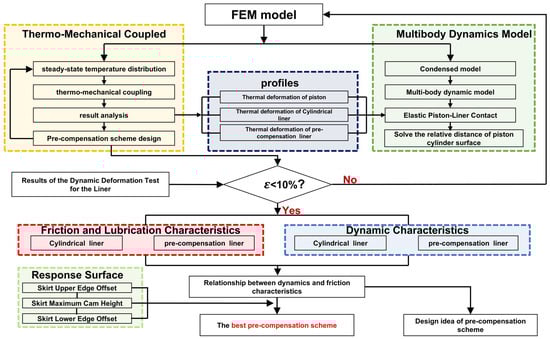
Figure 1.
Research workflow.
2. Establishment of the Finite Element Model
2.1. Multibody Dynamics Theory
The lubricated contact between the cylinder liner and piston skirt was characterized using a hydrodynamic lubrication model [], which adopts the well-documented mass-conserving p–θ Elrod–Adams algorithm [,] for cavitation handling—this algorithm avoids mass conservation errors common in traditional cavitation models. To quantify the effect of surface roughness on oil film pressure distribution, Patir–Cheng flow factors were integrated into the model; these factors, derived from the average Reynolds equation by Patir and Cheng [].
Here, h(x,y,t) denotes the theoretical oil film thickness; p(x,y,t) the mean hydrodynamic pressure; the lubricant’s dynamic viscosity (assumed constant); (x,y,t) ∈ (0,1] the Elrod–Adams saturation or volume fraction = 1 in full-film regions and 0 < < 1 in cavitated regions); U the relative sliding velocity along the circumferential direction x; x and y the Patir–Cheng pressure–flow factors in the x- and y-directions, respectively; and s the Patir–Cheng shear flow factor. The flow factors x, y, and s are functions of the roughness ratio σ/h and the surface–texture orientation [].
2.2. Multibody Dynamics Model
In constructing the multibody dynamics model within AVL Excite, a key objective was to achieve a balance between predictive accuracy and manageable simulation times. To this end, specific modeling simplifications were implemented: the piston boss bearings, along with the connecting rod’s small-end and big-end bearings, were modeled as revolute joints (REVO). This approach eliminates non-critical degrees of freedom, thereby reducing the computational cost.
The multibody dynamics simulation model is shown in Figure 2, To ensure model fidelity, the piston, connecting rod, gudgeon pin, and cylinder liner were modeled as elastic bodies. Introducing surface profiles on the cylinder liner and piston skirt strongly influences the tribological behavior of the interface, even though the resulting quantities are typically small in magnitude []. Therefore, obtaining reliable predictions requires explicit consideration of the finite deformability of all components. The deformed shapes of these parts were obtained from an FST multi-physics coupled analysis (in Section 2.3) and incorporated into the multibody model.
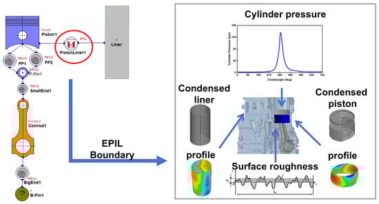
Figure 2.
Elastohydrodynamic lubrication model for piston skirt.
In the multibody dynamics model, considering three interfacial parameters (lubricant type, surface roughness, and surface coating) is crucial for constructing a physically accurate friction–lubrication analysis. The lubricant type determines oil film formation and load-carrying capacity through its viscosity–temperature and viscosity–pressure characteristics []. Surface roughness quantifies asperity contact and fluid pressure distribution under mixed lubrication via the average flow model. Surface coating affects boundary lubrication behavior by altering interfacial mechanical properties and wettability. The fundamental parameters of the frictional surfaces for the engine model used in this study are listed in the following Table 2.
Table 2.
Fundamental parameters of the frictional surfaces.
2.3. Thermal Deformation Profile Model
The deformation of the piston and cylinder liner was computed according to the governing equations of elasticity and heat transfer. The stress–strain analysis was based on the equilibrium, geometric, and constitutive relations of elasticity. The temperature field was obtained by solving the three-dimensional steady-state heat-conduction equation, accounting for internal heat sources. The cylinder liner deformation resulted from the coupled solution of the thermal and elastic fields; for its derivation process, refer to Ref. [].
A fluid–structure–thermal (FST) multi-physics coupled analysis was performed to investigate a turbocharged, intercooled diesel engine. Simulations were carried out under the rated operating conditions to evaluate the temperature distribution and deformation of the cylinder liner and piston.
To simulate the deformation of the cylinder liner and piston, CFD analysis of the cooling jacket was first performed using AVL FIRE 2023. The calculated temperature and convection heat transfer coefficients were then imported into Abaqus 2022 to carry out the thermo-mechanical coupled deformation analysis. The model was constructed based on the actual geometry and discretized with tetrahedral elements. As illustrated in Figure 3, six critical contact surface were defined within the assembly: cylinder head–bolt (tie constraint), cylinder head–gasket, liner–gasket, block–liner, block–gasket, and block–bolt.
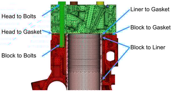
Figure 3.
FST-coupled liner deformation model.
The model’s boundary conditions comprise thermal and mechanical specifications. Thermal boundary conditions consisted of convective heat transfer specified on the cooling jacket, the inner cylinder-liner surface, the cylinder-head combustion surface, the intake and exhaust ports, and the outer cylinder-block surface.
Mechanical boundary conditions encompassed the peak in-cylinder combustion pressure, the piston lateral force, and bolt preloads []. The resulting temperature distributions and deformations of the piston and cylinder liner are shown in Figure 4.
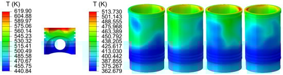
Figure 4.
Temperature distribution results of the piston and cylinder liner.
2.4. Mesh Independence Study
A mesh sensitivity analysis was performed on the cylinder liner deformation model to ensure that the results were not dependent on the discretization while maintaining reasonable computational expense. A series of mesh configurations, with sizes from 2 mm to 5 mm (corresponding to 10,816,047, 4,159,820, 3,356,177, and 2,515,388 elements, respectively), were evaluated. The mesh size of 5 mm was validated as the coarsest acceptable resolution, beyond which the model exhibited significant physical deviations. The maximum liner deformation and computational time under different mesh sizes are shown in Figure 5.
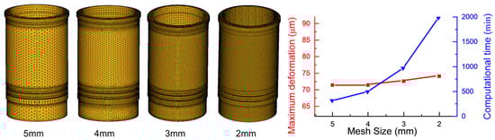
Figure 5.
Mesh independence study.
2.5. Model Validation
The predictive capability of the simulation model was assessed through experimental correlation. A specialized test bench, depicted in Figure 6a, was utilized to acquire real-time measurements of cylinder liner deformation and piston kinematics []. The equipment used in Figure 6a is listed in the accompanying Table 3.
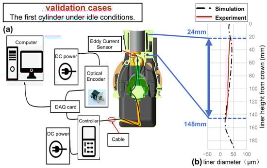
Figure 6.
Test bench design (a) and model validation (b).
Table 3.
Data on the measuring equipment.
Figure 6b compares the relative position between the liner and piston surfaces on the intake side of Cylinder 1 under idle conditions, showing measured data (solid line) versus CAE computational results (dashed line). The experimental data were acquired within the range of 24 mm to 144 mm above the liner bottom. Due to combined effects, including assembly tolerances and severe operational vibrations, the measured results contain numerous digital noises. Signal-to-noise ratio can be enhanced by implementing synchronous averaging based on crankshaft angle signals from the optical encoder. This method effectively separates periodic components from random noise. The comparison between experimental and simulation results demonstrates that the computational curves exhibit good agreement with the measured data, with relative error within 20%. This indicates that the model maintains high accuracy in predicting liner deformation, even under operating conditions.
3. Finite Element Analysis of Pre-Compensation Liners
3.1. Pre-Compensation Design for Cylinder Liners
A reverse geometric correction was introduced during the initial machining of the cylinder liner. This correction ensures that when the cylinder liner is subjected to actual operating loads, its inner-wall geometry approximates an ideal cylinder—ultimately achieving uniform contact between the piston skirt and cylinder liner, and optimizing lubrication performance and dynamic stability [,].
Informed by the mechanical and thermal loads on the cylinder liner and by deformation simulations of the engine in its initial configuration, five pre-compensation designs were developed. The pre-compensation schemes were as follows: a tapered liner (a) Scheme 1, a bottleneck-shaped liner; (b) Scheme 2, a spindle-shaped liner; (c) Scheme 3, an elliptical liner; (d) Scheme 4, and an elliptical–spindle composite liner; and (e) Scheme 5. The dimensional schematics of these five designs are shown in Figure 7 [].
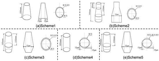
Figure 7.
Dimensional schematic of the pre-compensation design. Subfigures (a–e) represent five different design schemes, respectively.
The circumferential coordinate system on the cylinder liner is defined with the secondary-thrust side at 0°. Angles increase counterclockwise, assigning the flywheel side, main-thrust side, and pulley side to 90°, 180°, and 270°, respectively. Figure 8 shows that the circumferential distribution of the cylinder-liner profile under operating conditions differs among the pre-compensation schemes, and all profiles vary with circumferential angle. Based on these distributions, this section analyzes the effects of each scheme on piston dynamics and lubrication characteristics.
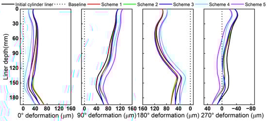
Figure 8.
Cylinder liner thermal profiles for different schemes.
3.2. Piston Dynamics
To assess the impact of cylinder liner shape on piston dynamics, the piston motion over one working cycle was compared across Schemes 1–5, with attention to radial displacement and tilt angle. As shown in Figure 9a,b, the influence of Schemes 1–5 on secondary piston motion varied markedly. Scheme 3 induced notable secondary piston motion near TDC, with the maximum radial displacement and tilt angle increasing by 0.07 mm and 0.018°, respectively, relative to the initial cylinder liner. Schemes 4 and 5, by reducing the diameter at the major and minor thrust sides, provided better piston support and thereby reduced the maximum radial displacement and tilt angle. Scheme 2 offered substantial piston support under in-cylinder combustion pressure, resulting in a minimal effect on secondary motion. Relative to the initial cylinder liner, Scheme 2 increased the maximum radial displacement by only 0.001 mm and the maximum tilt angle by 0.009°.
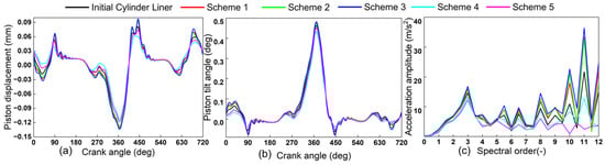
Figure 9.
Dynamics simulation results for different schemes. Subfigures: (a) piston displacement, (b) piston tilt angle, and (c) acceleration amplitude.
To further analyze the effect of liner shape on piston-slap excitation, the piston’s lateral acceleration along the major and minor thrust directions over one working cycle was extracted and analyzed. Applying a Fourier transform to this time-domain signal yielded acceleration amplitudes at various harmonics. As shown in Figure 9c, Schemes 1–3 significantly increased the lateral-acceleration amplitude, which is detrimental to mitigating piston–cylinder slap. In contrast, Schemes 4 and 5 exhibited lower lateral-acceleration amplitudes than the initial cylinder liner, indicating effective mitigation of piston–cylinder slap.
3.3. Friction Loss
The piston-skirt friction loss comprises two components—hydrodynamic friction and rough-contact friction []. To evaluate the impact of different pre-compensation schemes on piston-skirt friction, we compared the variation in friction loss with crank angle over one working cycle across Schemes 1–5 and the initial cylinder liner.
Figure 10 shows the curves of total contact friction loss (a), hydrodynamic contact friction loss (b), asperity contact friction loss (c) versus crankshaft angle for Schemes 1–5 and the initial cylinder liner. A comprehensive analysis indicates that Schemes 4 and 5 increase piston-skirt friction loss, thereby degrading friction performance. In contrast, Schemes 1–3 significantly reduce skirt friction loss during operation. Among them, Scheme 2 shows the greatest reduction. Relative to the initial cylinder liner, the cycle-averaged total friction loss decreased by 0.064 kW, with rough-contact friction decreasing by 0.017 kW and hydrodynamic friction decreasing by 0.048 kW.
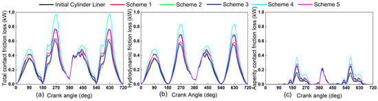
Figure 10.
Friction loss simulation results for different schemes. Subfigures: (a) total contact friction loss; (b) hydrodynamic contact friction loss; (c) asperity contact friction loss.
3.4. Contact Pressure
The contact pressure at the piston skirt and cylinder liner interface is a primary determinant of the interfacial contact state and friction performance []. Elevated pressure levels promote accelerated wear, ultimately compromising engine reliability and service life. A comparative analysis was therefore performed to evaluate the effect of liner shape on lubrication, by examining the peak contact pressure as a function of crank angle over one working cycle for Schemes 1–5 and the initial cylinder liner.
Figure 11 shows the peak total contact pressure (Figure 11a), peak oil film pressure (Figure 11b), peak asperity contact pressure (Figure 11c) versus crankshaft angle for Schemes 1–5 and the initial cylinder liner. Across all schemes, three peaks recur: early compression, early power, and early exhaust. During early compression and early exhaust, the peak pressure concentrates at the upper portions of the main and secondary thrust sides, approximately 40 mm above the piston bottom. During the early power stroke, burst-pressure-induced piston wobble loads the top edge of the secondary-thrust side, concentrating the peak pressure in this region.
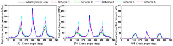
Figure 11.
Contact pressure simulation results for different schemes. Subfigures: (a) peak total contact pressure; (b) peak oil film pressure; (c) peak asperity contact pressure.
3.5. Oil Film Thickness
A key parameter for lubrication and friction reduction at the skirt–liner interface is the oil film []. The minimum oil film thickness over one working cycle was therefore benchmarked against the initial cylinder liner to assess the impact of Schemes 1–5. The resulting oil film distribution for each case is provided in Figure 12a.
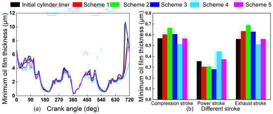
Figure 12.
Minimum oil film thickness simulation results for different schemes. Subfigures: (a) minimum oil film thickness at different crank angles; (b) minimum oil film thickness across different strokes.
Figure 12b depicts the evolution of the minimum oil film thickness over the course of an engine stroke. During early compression and exhaust, Schemes 1–3 and 5 increase the thickness by up to 0.107 µm and 0.127 µm, respectively, while Scheme 4 reduces it by 0.044 µm and 0.050 µm. Conversely, during early power, Schemes 1–3 decrease the thickness by 0.051–0.074 µm, whereas Schemes 4 and 5 increase it by 0.092 µm and 0.018 µm, respectively.
3.6. Comprehensive Comparison
Based on a comprehensive comparison of piston dynamics, skirt friction, and lubrication among Schemes 1–5 and the initial cylinder liner, Figure 13 shows the comparison across all schemes.
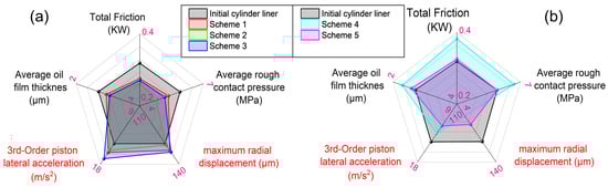
Figure 13.
(a,b) Comprehensive comparison of different schemes.
As shown in Figure 13a, Schemes 1–3 reduce skirt friction and improve lubrication, delivering superior dynamic characteristics near the combustion TDC; among them, Scheme 2 achieves the largest friction reduction.
By contrast, as illustrated in Figure 13b, Schemes 4 and 5 do not reduce skirt friction or improve lubrication but do enhance piston dynamics near the combustion TDC, with Scheme 5 exhibiting the most pronounced improvement.
Further analysis indicates that increasing the radial diameter in the lower section through pre-compensation improves lubrication of the piston–liner pair, thereby reducing piston–skirt friction loss.
4. Response Surface Method for Optimizing the Piston Skirt Profile
4.1. Experimental Design and Response Surface Establishment
To achieve multi-objective optimization of key piston skirt parameters (as shown in Figure 14) crown point height (H), upper skirt offset (Ct), and lower skirt offset (Cl) in Scheme 2, RSM was employed. As supported by LV et al. [], precise adjustment of these parameters can suppress piston secondary motion and improve friction performance.
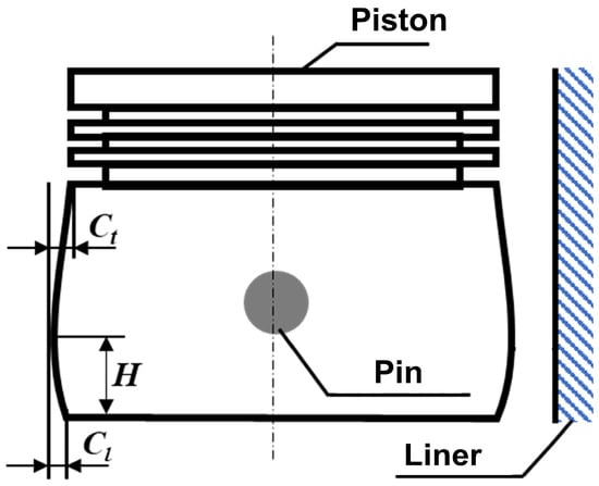
Figure 14.
Schematic of the investigated parameters.
Two core responses were selected: Y1 (cycle-averaged total skirt friction loss) and Y2 (third-order lateral acceleration). BBD was used to build a 17-experiment matrix (Table 4), and polynomial regression fitted the parameter-response mapping (Equations (2) and (3)) [,].
Table 4.
Box–Behnken test design.
The simulation model was used to evaluate the 17 design points, and the results were subjected to ANOVA. Polynomial regression was applied to relate the design factors to the responses, yielding the equations for Y1 and Y2 over one working cycle, as given in Equations (2) and (3) [].
The calculated and model-predicted values of the average skirt friction loss and the third-order lateral acceleration. The regression model for average total friction loss is statistically significant (p < 0.0001), with R2 = 0.9556. Similarly, the model for third-order lateral acceleration is highly significant (p < 0.0001) with R2 = 0.990. Both models have R2 > 0.9, with the latter approaching 1, indicating high reliability and predictive accuracy for friction loss and third-order lateral acceleration over one working cycle.
4.2. Optimization Setup and Objectives
Greater response surface curvature indicates more significant parameter interaction effects on Y1/Y2 []. Response–surface plots illustrating the interactive effects of H, Ct, and Cl on average total friction loss and third-order lateral acceleration are shown in the corresponding Figure 15.
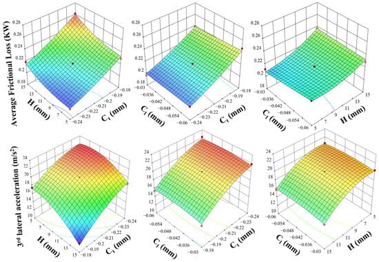
Figure 15.
The influence of interaction on the Y1 and Y2.
Based on the above analyses, although Scheme 2 significantly reduces the cycle-averaged piston–skirt friction loss, its secondary-motion performance is inferior to the initial original engine cylinder liner. This is manifested by a larger maximum piston tilt angle and maximum radial displacement. Furthermore, Fourier analysis of the lateral acceleration shows that the third-order component in Scheme 2 exceeds that of the initial cylinder liner.
Therefore, in the optimization, the highest priority was assigned to third-order lateral acceleration, whereas the lowest priority was given to cycle-averaged friction loss. The optimal combination of piston-skirt profile parameters obtained from the optimization was Ct = −0.189 mm, H = 15 mm, and Cl = −0.06 mm. The initial values and the predicted optimal values are listed in Table 5. Comparison of Figure 15 shows that modestly decreasing the upper skirt offset, while increasing the crown point height and the lower skirt offset, led to a slight increase in skirt friction loss but effectively reduced the third-order lateral acceleration of the piston. These results indicate that appropriate optimization of the piston–skirt profile mitigates secondary motion and reduces piston–cylinder slap excitation.
Table 5.
Response surface optimization results.
4.3. Post-Optimization Results
The optimized skirt parameters were implemented in the piston–connecting rod–crankshaft–cylinder–liner multibody dynamics model in AVL-Excite 2023 R1. Simulations analyzed the piston’s secondary motion in Scheme 2 after parameter optimization, with results compared against the initial cylinder liner.
As shown in Figure 16a,b, the piston motion of the optimized design in Scheme 2 remains largely consistent with the initial cylinder liner, with differences confined to specific crank-angle ranges. Compared with the initial cylinder liner, the piston’s secondary motion is reduced after optimizing the key skirt parameters. Specifically, the maximum radial displacement decreases from 0.128 mm to 0.113 mm, a reduction of 0.015 mm, while the maximum tilt angle decreases from 0.463° to 0.462°, a reduction of 0.001°.
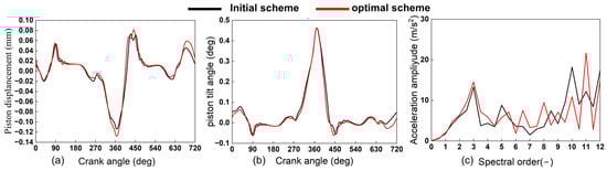
Figure 16.
Comparison of piston dynamic before and after optimization. Subfigures: (a) piston displacement, (b) piston tilt angle, and (c) acceleration amplitude.
Figure 16c compares the piston lateral-acceleration signals between the initial cylinder liner and optimized designs. A Fourier transform was applied to obtain harmonic amplitudes. For the third-order component, the amplitude decreases from 14.53 m/s2 to 13.26 m/s2 in the optimized design. These results indicate that optimizing the key skirt parameters mitigates secondary motion and reduces impact excitation on the cylinder liner.
Figure 17 further compares the piston–skirt friction loss over one working cycle between the initial cylinder liner and optimized designs. Figure 17a shows the total friction loss, with the average decreasing from 0.307 kW to 0.250 kW for the optimized design. Figure 17b shows that the optimized design reduces hydrodynamic friction loss throughout the cycle, with the average decreasing from 0.262 kW to 0.213 kW. Figure 17c indicates that, although asperity-contact friction loss increases slightly during late compression and early power because of the profile change, it is reduced for most of the cycle, with the average decreasing from 0.045 kW to 0.037 kW.
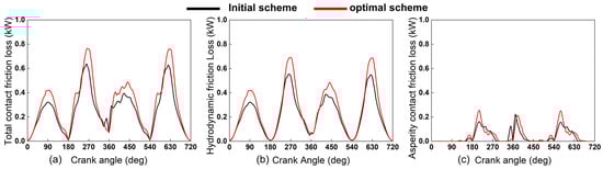
Figure 17.
Comparison of friction losses at the piston skirt before and after optimization. Subfigures: (a) total contact friction loss; (b) hydrodynamic contact friction loss; (c) asperity contact friction loss.
Table 6 compares the before-and-after parameters over one working cycle. The integrated data and computational results show that, after selecting the optimal liner shape, lubrication of the piston–liner pair improves and friction loss is notably reduced. Furthermore, subsequent optimization of the piston–skirt profile suppresses secondary motion and impact excitation on the liner, while maintaining the improved lubrication and reduced friction.
Table 6.
Comparison of results of various parameters before and after optimization.
5. Conclusions
- 1.
- Compared with the baseline engine configuration, adoption of the bottleneck-shaped liner reduced the cycle-averaged total piston skirt friction loss by 0.064 kW, representing a reduction of 20.8%. The peak asperity contact pressure decreased by 1.16 MPa, a reduction of 19.7%. In terms of piston dynamics, the maximum radial displacement increased by only 0.001 mm, and the maximum tilt angle increased by only 0.009°, both changes being minimal. Among the five pre-compensation schemes investigated, the bottleneck-shaped liner provided the most significant improvement in piston skirt lubrication and friction/wear reduction, while introducing the smallest influence on secondary piston motion.
- 2.
- After optimizing the key piston parameters based on the response surface model, the maximum piston radial displacement was reduced by 0.010 mm (8.13%), and the maximum tilt angle was reduced by 0.001°. The amplitude of the third-order lateral acceleration decreased by 1.27 m/s2 (8.74%), and the cycle-averaged total skirt friction loss was reduced by 0.057 kW (18.57%).
- 3.
- The pre-compensation design effectively enhances the dynamic and tribological performance of the interface. Future work will focus on refining the pre-compensation profile through more detailed optimization and extending this design approach to other similar reciprocating machinery systems.
6. Patents
Bi, Y. A device and method for measuring cylinder liner dynamic deformation using eddy current sensors. CN 202210262278.0, 25 July 2023.
CN 202210262278.0, 25 July 2023; He, H.; Shen, L. Multi-sensor parallel testing and analysis software for cylinder liner dynamic deformation based on LabVIEW, v1.0; Computer Software Copyright: 2022.
Author Contributions
Y.B.: Conceptualization and methodology. X.L.: Formal analysis and writing—original draft. S.L.: project management and visualization. M.T.: Investigation and project administration. Y.Y.: Writing—review and editing and data curation. H.H.: Software and validation. L.S.: Resources and methodology. G.Z.: Investigation and formal analysis. All authors have read and agreed to the published version of the manuscript.
Funding
This research was funded by Yunnan Fundamental Research Projects, grant number 202402AG050009 and the National Natural Science Foundation of China, grant number 52165032.
Data Availability Statement
The data that support the findings of this study are available on request from the corresponding author, Shaohua Liu, upon reasonable request.
Conflicts of Interest
Authors Yuhua Bi, Xinpei Lin, Shaohua Liu, Yueshan Yang and Lizhong Shen were affiliated with Yunnan Key Laboratory of Internal Combustion Engines, Kunming University of Science and Technology. Author Mingchao Tang and Guoqiang Zhang was affiliated with Kunming Yunnei Power Co., Ltd., China.Author Haining He was affiliated with Weifu High-Technology Group Co. ltd. The authors declare that this research was conducted in the absence of any commercial or financial relationships that could be construed as potential conflicts of interest.
Abbreviations
The following abbreviations are used in this manuscript:
| EHL | Elastohydrodynamic Lubrication |
| NVH | Noise, Vibration, and Harshness |
| TDC | Top Dead Center |
| BDC | Bottom Dead Center |
| CFD | Computational Fluid Dynamics |
| FST | Fluid–Structure-Thermal |
| RSM | Response Surface Methodology |
| BBD | Box–Behnken Design |
| ANOVA | Analysis of Variance |
References
- Chu, S.; Majumdar, A. Opportunities and challenges for a sustainable energy future. Nature 2012, 488, 294–303. [Google Scholar] [CrossRef]
- Holmberg, K.; Andersson, P.; Erdemir, A. Global energy consumption due to friction in passenger cars. Tribol. Int. 2012, 47, 221–234. [Google Scholar] [CrossRef]
- Liu, D.; Li, G.; Sun, N.; Zhu, G.; Li, L.; Wang, T.; Gu, F. Modelling and analysis of the vibro-acoustic coupling behaviours of the cylinder liner-water jacket system towards cavitation prediction. Mech. Syst. Signal Process. 2025, 225, 112307. [Google Scholar] [CrossRef]
- Alshwawra, A.; Pasligh, H.; Hansen, H.; Pohlmann-Tasche, F.; Dinkelacker, F. Increasing the roundness of deformed cylinder liner in internal combustion engines by using a non-circular liner profile. Int. J. Engine Res. 2021, 22, 1214–1221. [Google Scholar] [CrossRef]
- Ge, C. Tribofilm distribution and tribological analysis of piston ring–cylinder liner interfaces under realistic engine conditions. Tribol. Int. 2024, 201, 110250. [Google Scholar] [CrossRef]
- Milojević, S.; Stojanović, B. Determination of tribological properties of aluminum cylinder by application of Taguchi method and ANN-based model. J. Braz. Soc. Mech. Sci. Eng. 2018, 40, 571. [Google Scholar] [CrossRef]
- Gajević, S.; Marković, A.; Milojević, S.; Ašonja, A.; Ivanović, L.; Stojanović, B. Multi-Objective Optimization of Tribological Characteristics for Aluminum Composite Using Taguchi Grey and TOPSIS Approaches. Lubricants 2024, 12, 171. [Google Scholar] [CrossRef]
- Bukvić, M.; Vencl, A.; Milojević, S.; Skulić, A.; Gajević, S.; Stojanović, B. The Influence of Carbon Nanotube Additives on the Efficiency and Vibrations of Worm Gears. Lubricants 2025, 13, 327. [Google Scholar] [CrossRef]
- Alshwawra, A.; Pohlmann-Tasche, F.; Stelljes, F.; Dinkelacker, F. Enhancing the geometrical performance using initially conical cylinder liner in internal combustion engines—A numerical study. Appl. Sci. 2020, 10, 3705. [Google Scholar] [CrossRef]
- Zhu, D.; Cheng, H.S.; Arai, T.; Hamai, K. A numerical analysis for piston skirts in mixed lubrication—Part I: Basic modeling. J. Tribol. 1992, 114, 553–562. [Google Scholar] [CrossRef]
- Zhu, D.; Hu, Y.-Z.; Cheng, H.S.; Arai, T.; Hamai, K. A numerical analysis for piston skirts in mixed lubrication: Part II—Deformation considerations. J. Tribol. 1993, 115, 125–133. [Google Scholar] [CrossRef]
- Meng, Z.; Ahling, S.; Tian, T. Study of the effects of oil supply and piston skirt profile on lubrication performance in power cylinder systems. SAE Tech. Pap. 2019, 8. [Google Scholar]
- Zhao, B.; Dai, X.D.; Zhang, Z.N.; Xie, Y.B. A new numerical method for piston dynamics and lubrication analysis. Tribol. Int. 2016, 94, 395–408. [Google Scholar] [CrossRef]
- Meiser, J.; Deuß, T.; Ehnis, H.; Künzel, R. Friction power measurements of a fired gasoline engine—Influence of piston skirt geometry. MTZ Worldw. 2018, 79, 50–57. [Google Scholar] [CrossRef]
- Dimitrakopoulos, M.; Zavos, A.; Nikolakopoulos, P. Numerical study of the effect of ZnO/MWCNT lubricant additives on density and piston ring lubrication under cylinder liner distortions. Alex. Eng. J. 2025, 118, 618–637. [Google Scholar] [CrossRef]
- Bi, Y.; Xie, Q.; Zu, S.; Zhang, G.; Zhang, S. Profile optimization design and sealing performance research of cylinder holes based on pre-compensation. Intern. Combust. Engine Eng. 2024, 45, 98–108. [Google Scholar]
- Hibi, T.; Mita, T.; Yamashita, K. Improving the performance of diesel engines by bore profile control under operating conditions. SAE Tech. Pap. 2024, 12. [Google Scholar]
- AVL. EXCITE Power Unit User Manual; AVL List GmbH: Graz, Austria, 2023. [Google Scholar]
- Strozzi, A.; Baldini, A.; Giacopini, M.; Bertocchi, E.; Bertocchi, L. Achievement of a uniform contact pressure in a shaft–hub press-fit. Proc. Inst. Mech. Eng. Part C J. Mech. Eng. Sci. 2013, 227, 405–419. [Google Scholar] [CrossRef]
- Wang, Y. Research on optimization for the piston pin and the piston pin boss. Open Mech. Eng. J. 2011, 5, 186–193. [Google Scholar] [CrossRef]
- Patir, N.; Cheng, H.S. An Average Flow Model for Determining Effects of Three-Dimensional Roughness on Partial Hydrodynamic Lubrication. J. Lubr. Technol. 1978, 100, 12–17. [Google Scholar] [CrossRef]
- Wang, S.C.; Ding, Y.; Zhou, Y.; Wang, G.F. Temperature rise in frictional sliding contact of elastic–plastic solids with fractal surface. Tribol. Lett. 2025, 73, 2. [Google Scholar] [CrossRef]
- Bi, Y. Mechanical Characteristics and Deformation of Diesel-Engine Cylinder Liners. Ph.D. Thesis, Kunming University of Science and Technology, Kunming, China, 2012. [Google Scholar]
- Zu, S. Pre-Compensation Design for Deformation of Wet Cylinder Liners under Operating Conditions and Thermo-Mechanical Restoration Characteristics. Master’s Thesis, Kunming University of Science and Technology, Kunming, China, 2023. [Google Scholar]
- He, H.; Shen, L.; Zu, S.; Xu, Y.; Song, J.; Bi, Y. Dynamic deformation testing and analysis of wet cylinder liners using the eddy current method. Energies 2025, 18, 4421. [Google Scholar] [CrossRef]
- An, G.; Gao, K.; Dong, H.; Liu, B.; Li, L.; Hu, Z. Design Method of the Stroke Ring Based on Deformation Pre-Compensation. Actuators 2024, 13, 22. [Google Scholar] [CrossRef]
- Yang, Y. Influence of Liner Pre-Compensation Design on Piston Dynamics and Friction Loss. Master’s Thesis, Kunming University of Science and Technology, Kunming, China, 2024. [Google Scholar]
- Yu, H.; Zhao, S.; Liu, Y.; Li, J.; Zhang, B.; Ma, X.; Liu, L.; Zhang, H.; Xu, H. Study on wear characteristics of cylinder liner–piston ring under dynamic load. In Proceedings of the 9th International Conference on Mechanical Manufacturing Technology and Material Engineering (MMTME 2024), Singapore, 12 September 2025. [Google Scholar]
- Venkateswara Babu, P.; Syed, I.; Ben Beera, S. Influence of positive texturing on friction and wear properties of piston ring–cylinder liner tribo pair under lubricated conditions. Ind. Lubr. Tribol. 2019, 71, 515–524. [Google Scholar]
- Ishikawa, Y.; Kume, S.; Matayoshi, R.; Ito, A.; Yamashita, K. Improvement of measurement accuracy for oil film distributions on piston skirts by blocking diffuse fluorescence with a hole in a cover. Tribol. Int. 2025, 210, 110736. [Google Scholar] [CrossRef]
- LV, Y. Effect of Piston Skirt Profile Parameter on Secondary Motion and Lubrication Performance of Piston. J. Mech. Eng. 2018, 54, 100. [Google Scholar] [CrossRef]
- Khuri, A.I. Response surface methodology. In International Encyclopedia of Statistical Science; Lovric, M., Ed.; Springer: Berlin/Heidelberg, Germany, 2025. [Google Scholar]
- Zhao, Y.; Chen, Z.; Shi, W.; Yang, J.; Li, H.; Han, B.; Hou, S. Microstructure and tribological properties of supersonic plasma sprayed Ni-based high entropy alloy coatings optimized by response surface method. Intermetallics 2025, 183, 108820. [Google Scholar] [CrossRef]
- Chen, H.-Y.; Chen, C. A Study of the Response Surface Methodology Model with Regression Analysis in Three Fields of Engineering. Appl. Syst. Innov. 2025, 8, 99. [Google Scholar] [CrossRef]
Disclaimer/Publisher’s Note: The statements, opinions and data contained in all publications are solely those of the individual author(s) and contributor(s) and not of MDPI and/or the editor(s). MDPI and/or the editor(s) disclaim responsibility for any injury to people or property resulting from any ideas, methods, instructions or products referred to in the content. |
© 2025 by the authors. Licensee MDPI, Basel, Switzerland. This article is an open access article distributed under the terms and conditions of the Creative Commons Attribution (CC BY) license (https://creativecommons.org/licenses/by/4.0/).