Abstract
Conventional electro-permanent magnet (EPM) lifting/holding systems, typically based on NdFeB magnets, face efficiency limitations because continuous current is required either for standby condition to avoid accidentally attracting the objects around or for gently approaching and separating from sensitive iron-based target objects during gripping and releasing processes. Low Coercive Force (LCF) magnets offer an alternative, as their magnetization can be tuned with short current pulses and maintained without continuous current. However, this approach demands fast and precise flux control to eliminate the issues mentioned above. This paper introduces a novel flux control method based on the Hill Climb Search (HCS) algorithm. Once the required flux is identified, the system rapidly adjusts the magnetization of LCF magnet by applying optimized pulse trains within a short time. Experimental evaluation confirms that the proposed method effectively establishes and sustains the target magnetization level without additional current input. This approach has significant potential to advance and expand the use of Low Coercivity EPM systems as an alternative to classical systems.
1. Introduction
An electromagnet (EM) system utilizes the magnetic field to generate lifting force, offering a reliable, efficient way of handling ferromagnetic materials in industries such as manufacturing, construction, and recycling [1,2,3,4,5]. Compared to conventional mechanical lifting methods, EM systems provide advantages including rapid switching, reduced wear and tear, high lifting capacity relative to size, and flexible control of magnetic force for improved safety and precision [6,7,8]. However, EM lifting systems require a continuous power supply from the moment of clamping until release. Conventional electromagnetic systems are unable to retain residual magnetic flux once the power is removed, resulting in the complete loss of the holding force in the absence of excitation. This makes EMs inherently not fail-safe, since any power outage results in an immediate loss of holding force. In addition, the continuous holding current leads to significant power losses during long-term operation due to high thermal dissipation in the coils. Although EMs are easy to control, they are inefficient for prolonged industrial clamping tasks [9,10,11].
EPM-based lifting systems have been developed to offer substantial improvements in energy efficiency compared to EM [11,12]. Unlike EM system, EPMs can generate a holding force without continuous electrical excitation, thereby significantly reducing operational energy costs [13]. Recent studies have demonstrated their potential in industrial material handling. For example, rare-earth magnets (NdFeB)-based lifting system was shown to deliver high force density and low energy consumption in [14]. Similarly, intelligent design methods, such as fuzzy expert system optimization, have been applied to lifting chuck systems to enhance reliability and adaptability to variable industrial conditions [15]. Despite these benefits, conventional EPM lifting systems exhibit an operational drawback: unloading requires continuous current opposed to the permeant magnet flux, and once this current is removed, the magnetic force is inherently restored. This characteristic complicates precise control, particularly in unloading stages, and raises safety concerns when handling heavy or sensitive loads. Moreover, NdFeB is a rare-earth based magnet, known for limited global availability and hence introduces high costs to its plications.
The difficulty of conventional EPMs may be resolved with the adoption of hybrid EPMs, which strategically combine LCF and High Coercive Force magnets (HCF) to achieve transition from neutral state to working state through the process of magnetizing and demagnetizing. In these designs, an HCF magnet such as NdFeB provides strong baseline magnetic flux, while an LCF magnet allows us to control the direction and magnitude of flux with short electrical pulses [16]. This architecture provides fail-safe holding force since electrical input is only required during magnetization or demagnetization, thus addressing the high energy losses inherent to EMs [17,18]. Similarly, another study proposed a method to reduce the leakage flux and enhance the effective flux of EPM lifting system [19]. This method optimizes the arrangement of hybrid EPM and improves lifting capacity without proportionally increasing energy demand. Other investigations, such as the design and development of a telescopic beam for EPM lifter system [20], illustrate practical engineering solutions for scaling hybrid EPM devices for industrial material handling. Moreover, recent advances in magneto-responsive soft actuators [21] suggest that hybrid excitation principles can be extended to robotic grasping systems, expanding the potential of EPM technology beyond heavy lifting into precision manipulation. Hybrid EPM systems outperform conventional EM and EPM systems since they eliminate continuous power consumption during operation and maintain fail-safe holding. However, their dependence on rare-earth magnets still raises concerns regarding cost, sustainability, and supply chain. Furthermore, due to the presence of HCF magnet, the flux in proportion to varying load demands is not precisely controllable. As a result, hybrid EPM systems may unexpectedly clamp onto surrounding ferromagnetic objects, creating potential safety hazards and limiting their controllability in dynamic environments. As an alternative to high coercivity EPM systems, Low Coercivity EPM (LC-EPM) systems may overcome the mentioned drawbacks if the magnetization level of the LCF magnet is properly adjusted. Conventional flux control methods, either based on PI [22,23] or hysteresis controllers that are typically applied to motors, are not suitable for this application since flux control in LC-EPM is based on residual flux measurement after current excitation is fully removed. This makes the mentioned method suffer from accuracy and large oscillations. Model predictive control approaches such as in [24,25] may be used in the control but they are usually sensitive to parameter changes due to thermal variations and magnetic saturation in the core. Furthermore, the magnetization and demagnetization characteristic of the LCF magnet naturally shows significant deviation, and therefore, any of the mentioned methods are not appropriate for flux control in LC-EPM systems. Hill Climb Search (HCS) is an iteration-based, local optimization algorithm that finds a local optimal solution by repeatedly taking small steps toward improving the objective function and is widely used for MPPT implementations in renewable energy systems. It provides independence from system characterization during implementation and has the potential to overcome the drawbacks of control approaches mentioned above.
In this study, a fast and precise flux control method has been presented for LC-EPM systems. The proposed control is based on HCS, which controls the magnetization level of FeCrCo magnet by generating current pulse trains bidirectionally. The HCS method is independent from core and PM characteristics and hence provides reliable magnetization control in any operation condition. Additionally, the control approach can be easily adapted to other LC-EPM or hybrid EPM systems. Therefore, LC-EPM systems equipped with HCS-based flux control have significant potential to provide sustainable, safer, and energy efficient lifting technology.
2. Basics of LC-EPM System
2.1. Magnetic Material Characteristics and Energy Principle
To understand the basics of EPM lifting system, the magnetic behavior of PMs needs to be first analyzed. The relationship between magnetic field intensity H and flux density B and in magnetic materials (including PMs) can be formulated as
where is the permeability of free space and M is the magnetization of the material. This relationship is displayed in Figure 1 for two PMs, which are NdFeB and FeCrCo. Key parameters obtained from the hysteresis loop include the remanent flux density , coercivity . NdFeB magnets are characterized with high Br, which is desirable for EPM applications. However, due to large Hc, magnetization level cannot be controlled with a pulse current. On the other hand, FeCrCo magnet exhibits high Br as NdFeB but low Hc, which makes it suitable for magnetization control.
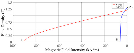
Figure 1.
B-H curves of NdFeB vs. FeCrCo magnets.
Figure 2 shows the magnetic equivalent circuit of the system. Lifting/holding applications in an EPM directly related to the flux and, hence, force developed in the core. Figure 2 displays the equivalent circuit that is considered in deriving the equations of the EPM system. If the saturation in the magnetic core is neglected, the total reluctance of the magnetic system can be expressed as
where x represents variation in air gap and is the total reluctance, is the magnet reluctance, and is core reluctance. The total flux ϕ can then be written in terms of magnetomotive force (mmf) and total reluctance as
where the flux obtained from the current flow in the coil and is the magnet flux, N is the no. of turns of the coil, i is the coil current, is PM length, and is the permeability of the magnet. Total field energy is the sum of stored energy in the core, in the air gap, and in the magnet:
where each contribution can be expressed as
Assuming constant current and linear demagnetization curve of the magnet, the total field energy Wf can be simplified as
Using coenergy expression may be more convenient to find the force if the coil current is selected as a control parameter. That is
The force F developed in the air gap is the coenergy variation with respect to air gap:
where Ag is the effective cross-sectional area of the air gap.
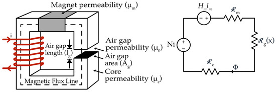
Figure 2.
Magnetic equivalent circuit.
2.2. Structure of the Proposed System
Figure 3 shows the control system configuration of the LC-EPM system. It consists of a DC voltage source that supplies power to a current pulse generation circuit (CPG), which is controlled by gate signals from a microcontroller unit. The CPG circuit controls the current magnitude as well as the current direction. The generated current pulses are delivered to the coil that is wound on magnetic core, which is formed by Si steel and FeCrCo magnet. An iron bar load separated by an air gap is used to complete the path for the flux. A current sensor monitors the applied current pulses, while a flux sensor embedded in the clamp unit measures the resulting magnetic flux. The measured flux signal is sent to the analog output to the microcontroller for closed-loop control. The microcontroller is programmed with MATLAB Simulink and communicates with a control interface through serial communication, enabling user control and monitoring of the system in real time. The specifications of the equipment that are used in the experiment are described in Table 1.
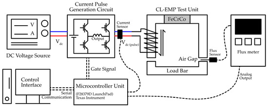
Figure 3.
Control configuration and components of EPM system.

Table 1.
Specifications of the equipment.
2.3. Pulse Generation Circuit
In Figure 4, the CPG circuit is designed using a full-bridge configuration of four IGBT switches (T1–T4), each driven by isolated gate drivers (GD1–GD4). The primary function of this circuit is to control both the direction of current through the load and to cut off the current according to reference input, enabling precise magnetization and demagnetization control. Control signal S1 simultaneously drives IGBTs T1 and T3, allowing current to flow in one direction for magnetization, while control signal S2 drives IGBTs T2 and T4, reversing the current flow for demagnetization. To provide proper isolation and stable gate drive voltage, isolated DC-DC converters (PS1–PS3) are used, each converting a 24 V input into a 15 V isolated output. The gate drivers are referenced to different potentials depending on the switching state of the IGBTs, and without proper isolation, biasing or short circuits could occur. The upper-leg switches T1 and T3 have separate isolated DC to DC converter (PS1 and PS3), while the lower-leg switches T2 and T4 share the same one (PS3) since they are both referenced to the common negative rail of the DC bus, allowing them to safely operate with a single isolated power supply. The components and parts used to develop the CPG circuit are listed in Table 2.
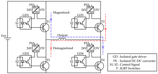
Figure 4.
Circuit diagram of CPG circuit.
Table 2.
Specification of the integrated electronic parts in CPG circuit.
2.4. Magnetic Circuit
Figure 5 shows the structure of the EPM system. It includes a two silicon steel cores structure. The left side core houses a FeCrCo permanent magnet on one leg. The right side of the core is treated as the load section, where an iron bar or workpiece can be positioned to experience the magnetic clamping effect. A copper coil with a wire diameter of 1 mm and 100 turns is wound around the magnet leg, allowing current pulses to dynamically adjust the magnetic flux. The flux path is guided through the core and across the air gap, where the effective clamping force is developed. To facilitate performance evaluation under different operating conditions, the air gap is configured to be adjustable, enabling systematic testing of the relationship between air gap length, flux density, and magnetizing current. The specifications of the materials used in the EMP test unit are listed in Table 3.
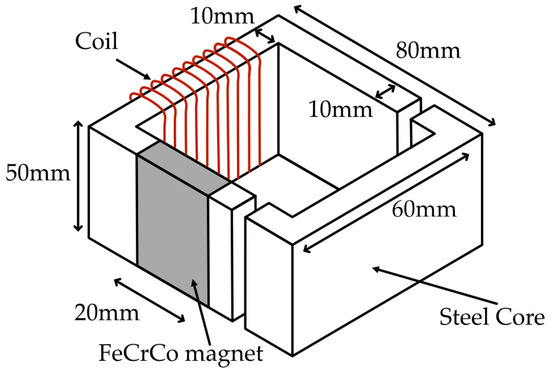
Figure 5.
Structure of LC-EPM test unit.
Table 3.
Material specification of LC-EPM test unit.
3. Proposed Magnetic Flux Control System
The magnetic flux control system is designed in two stages to achieve precise regulation of the magnetization flux. In the first stage, only the coil current is controlled using a closed-loop feedback system, where the input command is the desired current and the actual coil current is measured through a current sensor. This approach ensures accurate control of the magnetizing and demagnetizing current pulses applied to the coil. In the second stage, the primary control objective shifts from current to magnetic flux. In this approach, a dual-feedback closed-loop system is employed by utilizing both current and flux sensor measurements.
3.1. Closed-Loop Current Control
The first stage of the magnetic flux control system focuses on regulating the coil current using a closed-loop feedback scheme, as illustrated in Figure 6. A reference current is provided as the input command, which represents the desired magnetizing (forward) or demagnetizing (reverse) current to be applied to the EPM lifting unit. This reference is compared with the actual coil current, measured through a current sensor. The comparator calculates the error between the reference and measured current, and this error signal is used to adjust the switching of the current pulse generation circuit. The current pulse generation circuit, powered by the DC supply, delivers the required current pulses to the magnetic clamp unit while maintaining the commanded current level. This closed-loop control enables precise control of the applied current magnitude and direction, which is essential for producing consistent excitation pulses for flux control in the later stage.
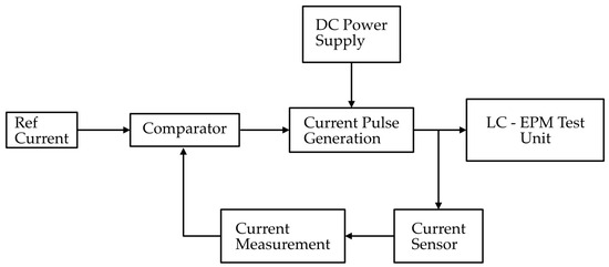
Figure 6.
Block diagram of closed-loop current control.
3.2. Hill Climb Search-Based Closed-Loop Flux Control
In the second stage of the control system, the objective is to directly regulate the magnetic flux of the clamp unit rather than only the coil current. As shown in the Figure 7, this stage is built on top of the first-stage current control loop, which now serves as the inner loop. The reference input in this case is a desired flux value, which is compared with the actual flux measured by the flux meter. Since the relationship between applied current and resulting flux is nonlinear and affected by magnetic hysteresis, the reference current is not predetermined but instead calculated dynamically using a HCS algorithm. This method adjusts the reference current iteratively until the measured flux converges to the commanded flux. This calculated reference current is then passed to the inner current control loop, which ensures that the magnetic clamp unit receives precise current. By combining the fast response of the inner current loop with the adaptive optimization of the outer flux loop, this two-stage system achieves accurate and stable flux regulation.
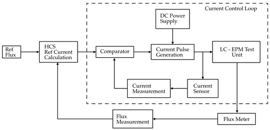
Figure 7.
Block diagram of closed-loop magnetic flux control.
The HCS algorithm is an iterative, gradient-free optimization method widely applied in artificial intelligence and in energy harvesting systems, particularly in Maximum Power Point Tracking (MPPT) for photovoltaic and wind energy applications. In these domains, the relationship between the control input and the output is typically nonlinear and lacks an explicit analytical model, which limits the applicability of conventional linear model-based control methods. Instead, HCS operates by incrementally adjusting the input variable and monitoring the output response. When the adjustment leads to an improvement in the output, the algorithm continues in the same direction. Conversely, if the response diverges from the target, the direction of adjustment is reversed.
HCS method can be effectively extended to flux control of EPM system, where the nonlinear and hysteretic nature of ferromagnetic materials complicates direct modeling of the relationship between excitation current and residual flux. Classical linear control methods such as PID and hysteresis control are not suitable for EPM flux control because these methods rely on continuous feedback between input and output signals. In an EPM system, the total magnetic flux during excitation is a combination of electromagnetic flux produced by the input current and residual magnetic flux retained in the material after excitation. However, precise flux control requires feedback based solely on the residual flux measured after the excitation current has been fully removed. Continuous measurement schemes cannot isolate the residual flux component from the transient electromagnetic contribution. In these cases, discrete measurement approach is preferable, where the flux is sampled only during current-free intervals. The HCS method naturally satisfies this requirement by employing a discrete, iterative control process. It applies a current step, removes the excitation, measures the resulting residual flux, and updates the control input based on the flux deviation from the reference. In Figure 8, the initial excitation current is applied and then residual flux measured after the excitation current is zero. Based on whether the measured residual flux () increases or decreases toward the desired flux (), the direction and magnitude of will be set for next excitation. At kth step, the control input is updated based on the change in the system output as described in Equations (11) and (12).
where is the current step.
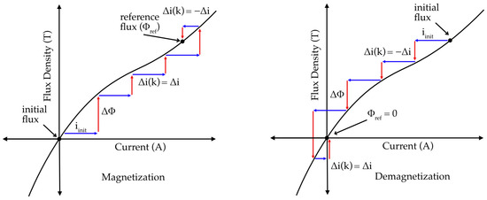
Figure 8.
Process of HCS control in magnetization and demagnetization.
Convergence of the HCS will reach when the steady state approach close to the after successive iterations. Near the steady state, local linearization can be written as
where is the nonlinear flux–current hysteretic relationship and non-monotonic in magnetic materials. Convergence depends on and the local slope of the flux–current curve. Smaller step sizes yield slower convergence but higher stability, while excessively large steps may lead to oscillation around . The convergence is guaranteed if the following condition is satisfied:
In Figure 9, the flowchart illustrates the process of the HCS-based flux control algorithm for the magnetic clamping system. The process begins by setting the desired flux reference Φref and measuring the feedback flux Φfb from the flux sensor. The initial step determines whether the reference flux is higher or lower than the measured flux, which sets the direction of the current: forward for magnetization (when Φref < Φfb) or reverse for demagnetization (when Φref > Φfb). Once the current direction is established, an initial current iinit is injected into the coil, and the resulting flux is measured. If the measured flux is still below the reference, the current is incremented by a predefined step , and the cycle repeats until the desired flux is approached. Conversely, if the measured flux overshoots the reference, the algorithm changes the current direction and continues the adjustment process. The loop terminates once the measured flux reaches the target flux value (Φref = Φfb). This iterative mechanism allows the system to adaptively reach the commanded flux level despite nonlinearities and hysteresis in the magnetization process.
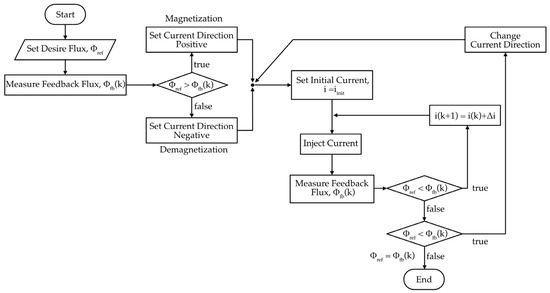
Figure 9.
Flowchart of the HCS-based flux control.
Although the proposed method is applicable to a wide range of LCF magnets, including Alnico, FeCoCr, and ferrite types, the experiments were performed using FeCoCr because it was readily available.
4. Experimental Setup and Results
4.1. Experimental Configuration and Conditions
The experimental platform for validating the proposed magnetic flux control system is shown in Figure 10. The system consists of a DC power supply, a pulse generation circuit, a microprocessor controller, an EPM test bench, current, and flux sensor. The DC power supply can provide 30 V up to 100 A, which provides current pulses by the pulse generation circuit. Current direction and flow are managed by the IGBT switches through gate signals generated by the microprocessor (MCU), while the current sensor feeds the excitation current back to the MCU in real time. The control software including current and flux control algorithms are built in MATLAB Simulink (R2024a) and are uploaded to the MCU before testing. The control file communicates with a host interface run on the computer and allows users to set reference values, monitoring waveforms and logging data. The EPM test bench itself consists of a steel core and FeCrCo magnet wound with a copper coil on one side, paired with another U-shaped steel core on the opposite side that acts as the load bar; both assemblies are enclosed in plastic housings. These two cores are mounted on an adjustable profile, allowing precise variation in the air gap within a closed magnetic circuit. A flux sensor of 1 mm thickness is inserted directly in the air gap to measure the magnetic flux.
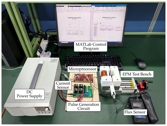
Figure 10.
Experimental setup.
4.2. Experimental Results
Experimental results are recorded under two scenarios. The first experimental test focused on validating the closed-loop current control of the proposed system as shown in Figure 11. In this test, reference current commands ranging from 5 A to 40 A were sequentially applied to the controller, so that the pulse circuit generates the desired current. The current can be injected into the coil in both positive and negative directions according to the reference value as shown in Figure 12. The residual flux is recorded after charging the coil. After each current excitation, the EPM unit was fully demagnetized back to the zero-flux condition before another trial. The experiment was conducted under three different air gap configurations corresponding to physical separations of 1 mm, 2 mm, and 3 mm per side of the U-shaped core, respectively, since the test bench has two separation points that double the effective air gap length. This systematic procedure allowed evaluation of the current flux characteristics, providing the basis for analyzing flux control behavior in later tests. The flux values of the experiments are recorded as Table 4.
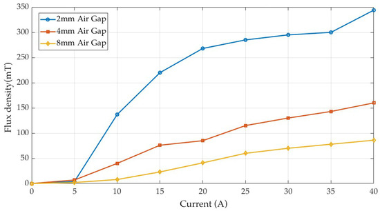
Figure 11.
Flux density vs. current characteristics at different air gaps.
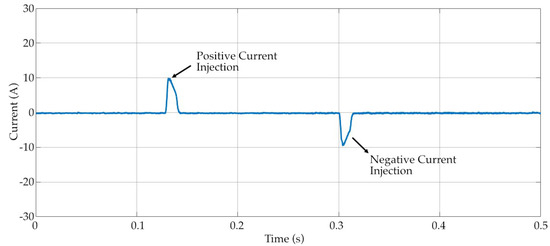
Figure 12.
Current pulse injection via closed-loop current control.
Table 4.
Flux density variation with respect to current and airgap length.
For the smallest air gap (2 mm), the flux increases rapidly with current, reaching over 340 mT at 40 A, but begins to saturate after approximately 20 A. At 4 mm air gap, the flux is significantly lower, with a maximum of about 160 mT at 40 A, and the curve shows a more linear progression with reduced slope. For the 6 mm air gap, the flux density is much weaker, not exceeding 90 mT even at the maximum current. By observing the curves, the flux–current relationships are nonlinear and differ significantly depending on the air gap. This behavior underscores the complexity of developing an accurate model-based approach. Consequently, an HCS-based control strategy is more suitable, since it adaptively converges to the target flux level without heavily relying on current and flux characteristics.
For testing the performance of the HCS-based flux control, reference flux is set to 300 mT and then reduced to zero. The results for this experiment are given in Figure 13. The number of pulses during the operation of magnetization and demagnetization is decided automatically according to the difference between the reference flux and measured flux. In Figure 13a, the current begins with an initial value of 5 A and is incrementally increased in discrete current steps of 1A during the magnetization process. Each current injection produces a corresponding rise in flux, as shown in Figure 13b, until the measured flux converges to the reference value of 300 mT. Once the reference flux is achieved, the current injection is stopped, and the residual flux remains stable at the reference point. During demagnetization, reverse current pulses are applied, resulting in a stepwise decrease in flux until it approaches zero. Small overshoot is observed due to the nonlinear hysteresis characteristics of the magnetic material and correction current is produced as part of the HCS control method. As described in the introduction, magnetization and demagnetization processes have their individual characteristics and therefore require significantly different current pulses. Therefore, the flux control with the classical methods is extremely difficult. However, HCS effectively follows the reference command in either direction or provides an accurate magnetization–demagnetization process, as seen in Figure 13a,b. The results demonstrate the ability of the HCS method to iteratively adjust the excitation current to reach and maintain the desired flux level, while also highlighting the effect of nonlinearity during flux reversal.
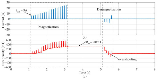
Figure 13.
The result of HCS-based flux control: (a) current, (b) flux density.
Current step ) and time step between each pulse ) could be adjusted to optimize the settling time of the HCS flux control. In Figure 14, HCS flux control is tested with different (2 A, 3 A) at (100 ms, 50 s). It is observed that larger current step 3 A and shorter intervals in Figure 14d result in faster magnetization, reducing the settling time from about 1.8 s to 0.6 s. However, this setting introduces higher flux ripple, which causes multiple overshoots at demagnetizing. Conversely, smaller current steps or longer intervals provide a smoother and more stable flux control approach with longer settling time. The demagnetization phase provides a smoother and more stable approach to bring the flux near zero. Overall, the HCS system achieves reliable and stable flux control. The control works well even in variation in current pulse amplitude and time steps between the current pulses. On the other hand, control response can be accelerated when the current pulse amplitude and time steps between the consecutive pulses have been optimized.
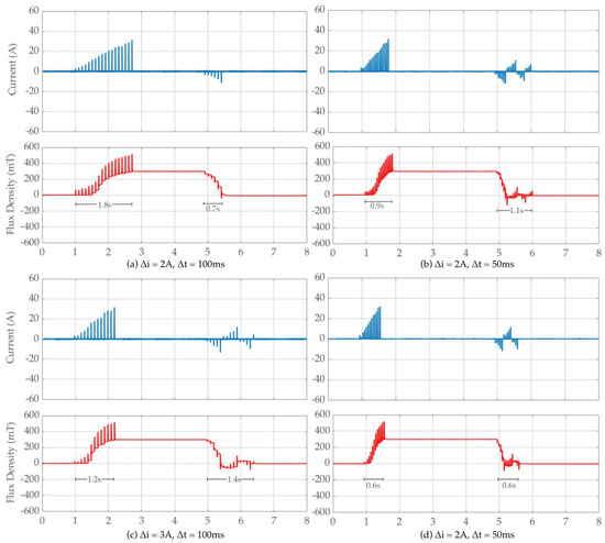
Figure 14.
The result of HCS-based flux control at (a) , (b) (c) , (d) .
5. Conclusions
This work proposed and experimentally validated rapid and precise flux control method for LC-EPM system, aiming to improve efficiency for lifting applications. Compared with conventional EPM systems, the use of LCF materials advantages the precise control over magnetic flux, improved operational safety, and lower environmental impact due to decreased reliance on rare-earth resources. Two complementary control methods were investigated: a closed-loop current control scheme and HCS-based flux regulation approach. The closed-loop current control was shown to accurately track the reference current across different air gap conditions, thereby ensuring precise excitation control. Building on this, the HCS-based method directly regulated the flux by adaptively adjusting the current, effectively handling the nonlinear and hysteretic nature of the flux–current relationship. To further quantify and optimize performance of the system, the HCS algorithm is investigated by systematically adjusting the parameters such as current step and discrete time step. The results confirm the expected trade-offs: larger current steps and shorter time steps significantly reduce settling time, introducing transient overshoot. Conversely, smaller current steps and longer time steps yield smoother, more accurate convergence and lower overshoot at the expense of slower response.
The proposed control strategies were implemented and validated using a dedicated experimental platform consisting of a custom EPM test bench, current pulse generation circuit and MATLAB-based control system. The results confirmed that the HCS method is reliable and easier to implement than model-based approaches, as it eliminates the need for complex magnetic characterization while maintaining robust convergence to the desired flux. The optimal HCS parameters are strongly dependent on physical characteristics of the system such as core size, desired flux magnitude, applied load, and material coercivity.
While the proposed method can serve as a foundation for future studies on adaptive control of EPM-based systems, some limitations should be acknowledged. The present study focused on flux regulation at the lab-scale prototype, and a complete lifting device prototype under industrial conditions has not yet been developed. The proposed HCS flux control of the LC-EPM system has potential to increase energy efficiency compared to the traditional EM systems during continuous operation, which needs to be investigated as future work. The presented flux control strategy forms an essential foundation for lifting applications and demonstrates strong potential for future extension to motor control systems, where precise and adaptive flux regulation is also critical.
Author Contributions
Conceptualization, F.K.; methodology, F.K.; software, Y.T.; validation, Y.T.; investigation, Y.T.; writing—original draft preparation, Y.T.; writing—review and editing, F.K.; visualization, Y.T.; supervision, F.K.; funding acquisition, F.K. All authors have read and agreed to the published version of the manuscript.
Funding
This work was financially supported by Metalart Corporation under an Industry-Academia-Government Collaboration project.
Data Availability Statement
The original contributions presented in this study are included in the article. Further inquiries can be directed to the corresponding author.
Acknowledgments
The authors acknowledge the invaluable assistance of Toshihiro Ohashi and Yosuke Emi from Metalart Corporation.
Conflicts of Interest
The authors declare no conflicts of interest.
Abbreviations
The following abbreviations are used in this manuscript:
| EM | Electromagnet |
| EPM | Electro-Permanent Magnet |
| LCF | Low Coercive Force |
| LC-EMP | Low Coercive Electro-Permanent Magnet |
| HCF | High Coercive Force |
| MPPT | Maximum Power Point Tracking |
| HCS | Hill Climb Search |
References
- Li, Y.; Lei, G.; Bramerdorfer, G.; Peng, S.; Sun, X.; Zhu, J. Machine Learning for Design Optimization of Electromagnetic Devices: Recent Developments and Future Directions. Appl. Sci. 2021, 11, 1627. [Google Scholar] [CrossRef]
- Devred, A.; Ballarino, A.; Bourcey, N.; Mangiarotti, F.; Milanese, A.; Petrone, C. Proof-of-Principle of an Energy-Efficient, Iron-Dominated Electromagnet for Physics Experiments. IEEE Trans. Appl. Supercond. 2024, 34, 1–7. [Google Scholar] [CrossRef]
- Yadav, A. Effect of Temperature on Electric Current, Magnets and Electromagnet. Int. J. Adv. Technol. 2016, 7, 167. [Google Scholar] [CrossRef]
- Afshar, S.; Khamesee, M.B.; Khajepour, A. Optimal Configuration for Electromagnets and Coils in Magnetic Actuators. IEEE Trans. Magn. 2013, 49, 1372–1381. [Google Scholar] [CrossRef]
- Sadesh, M.K.; Sudheep, S.; Mukilan, S.N.; Praveen Kumaran, R. Design of Electromagnetic Weight Lifting Gym Equipment. Int. Res. J. Eng. Technol. 2021, 8, 3595–3600. [Google Scholar]
- Lixing, X.; Wei, L.; Lixiang, W.; Yan, D. Electromagnetic Lifting Control System Based on BAS+PID Algorithm. In Proceedings of the 2020 IEEE International Conference on Artificial Intelligence and Computer Applications, ICAICA 2020, Dalian, China, 27–29 June 2020. [Google Scholar] [CrossRef]
- Davey, K. New Electromagnetic Lift Control Method for Magnetic Levitation Systems and Magnetic Bearings. IEEE Trans. Magn. 2004, 40, 1617–1624. [Google Scholar] [CrossRef]
- Alasli, A.; Çetin, L.; Akçura, N.; Kahveci, A.; Can, F.C.; Tamer, Ö. Electromagnet Design for Untethered Actuation System Mounted on Robotic Manipulator. Sens. Actuators A Phys. 2019, 285, 550–565. [Google Scholar] [CrossRef]
- Baek, S.K.; Oh, H.K.; Kim, S.W.; Seo, S., II. A Clamping Force Performance Evaluation of the Electro Mechanical Brake Using PMSM. Energies 2018, 11, 2876. [Google Scholar] [CrossRef]
- Ki, Y.H.; Lee, K.J.; Cheon, J.S.; Ahn, H.S. Design and Implementation of a New Clamping Force Estimator in Electro-Mechanical Brake Systems. Int. J. Automot. Technol. 2013, 14, 739–745. [Google Scholar] [CrossRef]
- Cai, W.; Gu, C.; Hu, X. Analysis and Design of a Permanent Magnet Bi-Stable Electro-Magnetic Clutch Unit for in-Wheel Electric Vehicle Drives. Energies 2015, 8, 5598–5612. [Google Scholar] [CrossRef]
- Ding, N.; Liu, C.; Duan, J.; Jiang, S. Design of Double-Drive Mechanism for Energy Saving Lifting Permanent Magnet. In E3S Web of Conferences, Proceedings of the 2019 4th International Conference on Advances in Energy and Environment Research (ICAEER 2019), Shanghai, China, 16–18 August 2019; EDP Sciences: Les Ulis, French, 2019; Volume 118. [Google Scholar] [CrossRef]
- Ding, N.; Cui, S.; Liu, C.; Duan, J.; Jiang, S. Review of Permanent Magnet Lifting Technology. In Journal of Physics: Conference Series, Proceedings of the 2020 6th International Forum on Engineering Materials and Manufacturing Technology (IFEMMT) 2020, Jilin, China, 17–19 July 2020; IOP Publishing Ltd.: Bristol, UK, 2020; Volume 1635. [Google Scholar] [CrossRef]
- Ding, N.; Liu, C.; Duan, J.S.; Jiang, S.N.; Hou, Y.Q. Energy Efficient Rare Earth Lifting Permanent Magnet. In IOP Conference Series: Earth and Environmental Science; IOP Publishing Ltd.: Bristol, UK, 2019; Volume 267. [Google Scholar] [CrossRef]
- Ding, N.; Zhang, D.T.; Song, Y.M.; Shi, J.; Ding, L.G. Lifting Chuck Design Based on Fuzzy Expert System. Adv. Mater. Res. 2013, 662, 653–656. [Google Scholar] [CrossRef]
- Kim, D.; Hashmi, A.; Hong, J. Energy Product and Coercivity of a Rare-Earth-Free Multilayer FeCo/FePt Exchange Spring Magnet. J. Korean Phys. Soc. 2013, 62, 918–923. [Google Scholar] [CrossRef]
- Oliva, F.; Faranda, R.S. Energy Efficiency in Magnetic Clamping Applications. In Proceedings of the 2022 IEEE International Conference on Environment and Electrical Engineering and 2022 IEEE Industrial and Commercial Power Systems Europe, EEEIC/I and CPS Europe 2022, Prague, Czech Republic, 28 June–1 July 2022. [Google Scholar] [CrossRef]
- Oliva, F.; Faranda, R.S. Energy Efficiency in Electromagnetic and Electro-Permanent Lifting Systems. Energies 2023, 16, 3550. [Google Scholar] [CrossRef]
- Baek, S.W.; Yoon, K.Y. Improving the Hybrid Electromagnetic Clamping System by Reducing the Leakage Flux and Enhancing the Effective Flux. Energies 2019, 12, 3762. [Google Scholar] [CrossRef]
- Deshmukh, A.; Bagdiya, A.; Deshpande, P.; Bhalerao, A.; Deokar, S.U. Design & Development of a Telescopic Beam for EPM Lifter System. Int. Res. J. Eng. Technol. 2016, 3, 2680–2689. [Google Scholar] [CrossRef]
- Sun, Y.; Ju, Y.; Wen, H.; Liu, R.; Cao, Q.; Li, L. Hybrid-Excited Magneto-Responsive Soft Actuators for Grasping and Manipulation of Objects. Appl. Mater. Today 2023, 35, 101917. [Google Scholar] [CrossRef]
- Khanabdal, S.; Banejad, M.; Blaabjerg, F.; Hosseinzadeh, N. A Novel Control Strategy of an Islanded Microgrid Based on Virtual Flux Droop Control and Direct Flux Fuzzy Control. Int. J. Eng. Trans. B Appl. 2021, 34, 1274–1283. [Google Scholar] [CrossRef]
- Jung, J.-W.; Leu, V.Q.; Do, T.D.; Kim, E.-K.; Choi, H.H. Adaptive PID Speed Control Design for Permanent Magnet Synchronous Motor Drives. IEEE Trans. Power Electron. 2015, 30, 900–908. [Google Scholar] [CrossRef]
- Ghanayem, H.; Alathamneh, M.; Nelms, R.M. Decoupled Speed and Flux Control of Three-Phase PMSM Based on the Proportional-Resonant Control Method. Energies 2023, 16, 1053. [Google Scholar] [CrossRef]
- Elmorshedy, M.F.; Almakhles, D.J.; El-Sousy, F.F.M. Modified Primary Flux Linkage for Enhancing the Linear Induction Motor Performance Based on Sliding Mode Control and Model Predictive Flux Control. IEEE Access 2023, 11, 26184–26198. [Google Scholar] [CrossRef]


Disclaimer/Publisher’s Note: The statements, opinions and data contained in all publications are solely those of the individual author(s) and contributor(s) and not of MDPI and/or the editor(s). MDPI and/or the editor(s) disclaim responsibility for any injury to people or property resulting from any ideas, methods, instructions or products referred to in the content. |
© 2025 by the authors. Licensee MDPI, Basel, Switzerland. This article is an open access article distributed under the terms and conditions of the Creative Commons Attribution (CC BY) license (https://creativecommons.org/licenses/by/4.0/).