1. Introduction
In the SAGD process, steam is injected into the reservoir via a horizontal wellbore, leading to the development of a low-pressure, vapour-saturated zone referred to as the steam chamber to support the drainage of bitumen to a parallel producer well [
1]. As the process progresses, this chamber expands both laterally and vertically. The injected steam is transported convectively from the wellbore to the outer edges of the steam chamber, facilitating heat transfer to the surrounding bitumen. Due to the minimal pressure gradient within the chamber—apart from the influence of gravity—both pressure and temperature remain relatively uniform throughout its volume [
1].
The successful deployment of SA-SAGD necessitates a comprehensive evaluation of both reservoir characteristics and operational parameters to ensure optimal solvent selection for co-injection [
2,
3]. It is generally anticipated that the injected solvent remains in the vapour phase, accompanying the steam until condensation occurs at or near the periphery of the steam-vapour chamber [
4]. Upon condensation, the solvent diffuses into the surrounding heavy oil while thermal energy is simultaneously transferred, enhancing the oil’s mobility. This dual mechanism of dilution and heating promotes more efficient mobilisation and drainage of the bitumen compared to thermal input alone [
5,
6,
7,
8]. As the mobilised oil is produced, the steam chamber progressively expands into the untouched regions of the reservoir, thereby continuously exposing fresh rock to solvent dilution and thermal stimulation [
9].
In SA-SAGD processes, the judicious selection of both solvent type and concentration plays a critical role in substantially enhancing the mobility of highly viscous oil or bitumen, surpassing the performance of conventional SAGD, which relies exclusively on thermal stimulation via steam. This integrated co-injection strategy capitalises on the synergistic effects of heat transfer and solvent dilution to facilitate improved fluid flow and boost overall recovery efficiency. Optimal outcomes are achieved when the solvent-steam mixture remains in the vapour phase during transport and condenses at or near the leading edge of the steam chamber [
10,
11]. At this interface, the steam imparts its latent heat of vaporisation while the solvent partitions into the bitumen, promoting gravitational drainage. For maximum efficacy, the solvent should exhibit compatible phase behaviour with steam, ensuring co-migration to the chamber boundary where simultaneous steam condensation and solvent dissolution act in concert to mobilise and displace the bitumen [
12].
Marked disparities in the phase behaviour of steam and multi-component solvent mixtures can result in uneven condensation dynamics. In such cases, the solvent may condense prematurely and separate from the steam front, becoming ineffective in diluting bitumen and instead being produced with minimal interaction, while steam continues advancing toward the edge of the steam chamber. When the selected solvent is overly heavy or introduced at elevated concentrations, it tends to remain predominantly in the liquid phase, thereby limiting its capacity to reach the vapour chamber interface. Rather than participating in vapour-phase transport, it drains downward under gravity and is directly produced, which compromises its efficacy in enhancing bitumen mobilisation [
13].
This investigation presents an experimental assessment of residual oil saturation resulting from both conventional SAGD and solvent-aided SAGD processes, incorporating the co-injection of multi-component solvents under conditions representative of the Long Lake reservoir and associated operational settings. The solvents evaluated—cracked naphtha and natural gas condensate—were introduced at concentrations between 5 and 15 vol% (based on the cold liquid equivalent of the combined steam–solvent system). Therefore, measuring the final residual oil saturation was a critical method for evaluating the effectiveness of the recovery process.
A series of high-pressure, high-temperature experiments were conducted using a partially scaled, manually controlled sand pack apparatus, designed to capture precise measurements of pressure, temperature, and fluid flow. Post-experimental characterisation of the produced fluids and core media offered valuable insights into the influence of solvent addition on critical performance metrics, including oil and water production rates, the steam-to-oil ratio (SOR), and the residual oil saturation. The findings from this study played a pivotal role in refining a field pilot implemented by Nexen Energy ULC (now CNOOC International Ltd., Calgary, AB, Canada) in September 2014 at the Athabasca Oil Sands. The experimental data contributed to the calibration of reservoir simulation models within permeability constraints and informed strategic adjustments to key operating parameters, such as steam temperature and injection pressure, to enhance overall process performance.
2. Background and Development of ES-SAGD
The simultaneous injection of solvent and steam SAGD presents a marked improvement over conventional SAGD, which relies solely on steam. Through the judicious selection of solvent type and concentration, the mobility of highly viscous bitumen can be significantly enhanced [
12]. This improvement is attributed to the synergistic effects of thermal energy and solvent-induced dilution, which collectively facilitate more efficient viscosity reduction. Consequently, this approach results in elevated oil recovery rates and reduced energy requirements when compared to steam-only SAGD operations [
14].
For maximum process efficiency in Enhanced Solvent-Assisted Steam-Assisted Gravity Drainage (ES-SAGD), the solvent–steam mixture must remain predominantly in the vapour phase until it reaches the boundary of the vapour chamber, where condensation is initiated [
15]. At this interface, steam condenses and releases its latent heat of vaporisation, with the condensate subsequently draining downward due to gravity. Concurrently, the solvent vapour condenses at the chamber boundary, allowing it to dissolve into the surrounding bitumen. This dissolution markedly lowers bitumen viscosity, enhancing its flow characteristics and promoting efficient gravitational drainage [
4].
The overall performance of ES-SAGD is largely governed by the selection of a solvent capable of co-travelling with steam in the vapour phase to the chamber boundary, where the dual mechanisms of steam condensation and solvent dissolution act in concert to mobilise bitumen [
16]. However, when heavier molecular weight solvents or high solvent concentrations are used, the solvent tends to remain in the liquid phase. As a result, it gravitates downward before reaching the vapour chamber edge and is often produced prematurely, contributing minimally to in situ dilution and reducing its efficacy [
17]. Conversely, lighter solvents in the vapour phase maintain their gaseous form until their partial pressure exceeds the dew point, triggering condensation. Importantly, solvent vapour may begin dissolving into the bitumen even before condensation, initiating viscosity reduction through molecular diffusion [
18].
As the diluted bitumen drains from the porous reservoir matrix, a new solvent–bitumen interface is continuously formed. This dynamic interface, typically exhibiting a reduced solvent concentration, is renewed through ongoing solvent interaction. The solvent not only reduces oil viscosity but also decreases interfacial tension, further facilitating enhanced bitumen mobility and improving the overall recovery process [
19].
2.1. Effect of Solvent Coinjection on SAGD Process
The effect of solvent on interfacial tension has been systematically examined in studies involving Lloydminster heavy oil exposed to various gaseous solvents, including methane, ethane, propane, and carbon dioxide [
20]. These investigations reveal that interfacial tension between the heavy oil and the solvents decreases nearly linearly with increasing pressure at reservoir temperature. Such reductions in interfacial tension have been shown to shift the balance between gravitational and capillary forces, resulting in a measurable decline in residual oil saturation [
21].
To enhance both heat and mass transfer across the interface separating the steam chamber from the bitumen-rich, unswept regions of the reservoir, the Steam-Alternating-Solvent (SAS) process was developed. This hybrid thermal-solvent strategy offers a more effective recovery mechanism by leveraging the advantages of both steam and solvent injection [
21].
Mathematical modelling further indicates that the coinjection of solvent with steam induces greater interfacial instability at the boundary of the vapour chamber, particularly at its lateral edges, than steam injection alone [
11]. This enhanced instability fosters increased mixing at the chamber boundary, contributing to improved bitumen mobilisation and higher oil production rates commonly observed in solvent–steam hybrid processes [
22]. These models also account for the solvent’s influence on interfacial tension within the oil–solvent mixture, reinforcing the conclusion that solvent dissolution plays a key role in lowering residual oil saturation and improving recovery efficiency [
16,
23,
24].
The effectiveness of a solvent in heavy oil recovery is primarily influenced by two critical parameters: (1) its diffusion rate, which governs the rate at which the solvent penetrates and mixes with the heavy oil, and (2) the quality of mixing, which is essential for reducing viscosity without inducing asphaltene precipitation. Historically, light hydrocarbons such as propane and butane have been favoured in their gaseous states for their high diffusivity [
25,
26]. Nevertheless, despite their favourable diffusion properties, these solvents often exhibit inadequate mixing behaviour, which can lead to substantial asphaltene precipitation [
27] and the associated risk of pore blockage and formation damage due to asphaltene deposition within the reservoir matrix [
28].
To mitigate this issue, higher-carbon-number solvents have been investigated in both gaseous [
14,
29,
30] and liquid forms [
31]. While solvents with a greater carbon number exhibit reduced diffusion rates, these provide superior mixing quality, thereby minimising asphaltene deposition [
32]. Furthermore, blending solvents containing aromatic constituents—such as light oils, distillate oil, or condensates—rather than using single-component alkanes enhances the mixing quality even further [
31].
2.2. Experimental Studies Utilising Multicomponent Solvents
Extensive research has explored the application of solvent injection for enhancing heavy oil recovery, encompassing both steam-assisted and steam-free approaches. Among these, significant attention has been directed toward the benefits of solvent coinjection in steam-driven processes, with particular emphasis on evaluating the performance of naphtha as an effective solvent.
Redford and McKay [
33] conducted comparative experiments evaluating the performance of lighter versus heavier solvents in thermal recovery applications. Their findings revealed that while heavier solvents achieved superior oil recovery, they also exhibited increased retention within the reservoir. Nevertheless, earlier investigations indicated that even under conditions conducive to asphaltene precipitation, the resulting permeability impairment was minimal. In parallel, Butler et al. [
1] examined the use of light solvents in vapour form—both independently, as in the VAPEX process, and in combination with steam and/or hot water—applied through a dual horizontal well configuration.
Farouq-Ali and Abad [
34] identified that the efficacy of solvent–steam processes is influenced by the slug size and injection strategy, noting that a solvent-to-bitumen ratio of 25% was excessive for optimal performance. Ziritt and Burger [
35] later demonstrated that significant permeability degradation occurs when just 2% of the oil experiences asphaltene precipitation. Further advancing this line of inquiry, experiments conducted by the same research group [
36] on the coinjection of light aromatic naphtha and steam in linear tar sand packs concluded that the most effective recovery was achieved by pre-injecting a naphtha slug ahead of steam in homogeneous formations.
Harris et al. [
37] performed ten laboratory-scale tests combining liquid naphtha with hot water to evaluate recovery performance. Their work reinforced the synergistic potential of solvent–heat coinjection. Yamazaki et al. [
38] confirmed that bitumen recovery is positively correlated with the rate of solvent injection, showing clear benefits from simultaneous solvent and steam delivery.
Building on this foundation, Nasr et al. [
39] assessed the effect of naphtha–steam coinjection within the SAGD framework, with particular emphasis on the role of vertical communication between well pairs in influencing recovery dynamics. Their study employed a scaled three-dimensional laboratory model with production governed by enthalpy constraints to ensure the exclusive production of liquid phases.
Finally, Das and Butler [
40] demonstrated that the precipitation of asphaltenes during the VAPEX process can further reduce oil viscosity, thereby enhancing production rates—highlighting a key benefit of solvent-driven mechanisms in improving oil mobility.
The boundary temperature, often considerably lower than the steam–solvent injection temperature, plays a critical role in governing both the bitumen drainage rate and the overall thermal efficiency of the recovery process [
41]. Their findings also indicate that light hydrocarbon solvents may adversely affect the production rate enhancement in SA-SAGD, particularly under lower operating pressures. However, by tailoring the composition of multicomponent hydrocarbon solvents—such as diluents—the performance of SA-SAGD can be significantly optimised, offering a strategic avenue for improving recovery efficiency.
3. Experimental Study
3.1. Setup Features for a Controlled and Efficient Process
Recognising the significant impact of heat losses and steam condensation on the fidelity and efficiency of SAGD-type core flooding experiments, a series of carefully engineered design and operational strategies were implemented to minimise thermal inefficiencies across the experimental system:
Temperature monitoring and regulation: Three thermocouples were strategically positioned to ensure continuous thermal oversight: one at the outlet of the steam generator, another at the injection point of the sand pack, and a third at its production outlet. This configuration enabled real-time tracking of temperature profiles, ensuring thermal consistency from steam generation through to production.
Comprehensive insulation of the sand pack assembly: To mitigate conductive heat losses through the metallic apparatus, the sand pack was initially wrapped in an insulating layer. Upon integration of the thermocouples, an additional thermal barrier was applied to reinforce thermal containment and minimise energy dissipation.
Reduction in heat loss in fluid delivery lines: The spatial layout of the steam generator and solvent delivery system was optimised by positioning them adjacent to the sand pack holder, thereby minimising transfer distances and associated heat losses. The entire assembly was encased in a thermally insulated enclosure, with all interconnecting lines wrapped in high-efficiency insulation materials and equipped with electric heating tape to preserve the desired steam temperature throughout transit.
Thermal insulation of injection and production lines: Both the injection and production conduits were insulated to maintain elevated fluid temperatures across the flow path. This precautionary measure was essential to prevent premature condensation, which could otherwise cause flow interruptions or plugging within the system.
Preconditioning of the sand pack: Before initiating steam injection, the lower portion of the sand pack was uniformly heated to 70 °C. This step simulated initial near-wellbore thermal conditions, facilitating the early establishment of thermal communication between the injection and production wells and promoting initial bitumen mobilisation.
Steam stabilisation prior to injection: To ensure thermal equilibrium within the steam generation and delivery subsystems, steam was circulated in a bypass loop—excluding the sand pack—until the targeted injection temperature and pressure were achieved. This pre-injection stabilisation phase was critical to ensuring consistent thermal conditions and stable performance during the core flooding experiments.
3.2. Experimental Setup
A physical sand pack model, measuring 31.6 cm in length with an inner diameter of 2.54 cm, was constructed to withstand high-temperature and high-pressure conditions representative of SAGD operations at the Long Lake field (207 °C and 230 psi). This apparatus was employed to investigate the influence of combined steam and solvent injection on the residual oil saturation within the porous medium following SAGD recovery. In addition to residual oil measurements, key performance metrics such as cumulative oil production versus injected steam volume, along with temperature distribution across the sand pack, were systematically monitored throughout the experiment and further analysed through post-test evaluation of the produced fluid samples.
Steam was introduced through a dedicated inlet port positioned 2.5 cm above the base of the sand pack in Zone 1. Thermal behaviour across the sand pack was continuously monitored using K-Type thermocouples (Omega, Inc., Manchester, UK), with four sensors (T1–T4) embedded internally at different axial positions. To enhance thermal management and reduce heat losses, four additional external thermocouples (T5–T8) were installed during the insulation phase.
The sand pack cell was equipped with removable end-caps that facilitated the integration of fluid inlet and outlet ports. A pre-milled distribution pattern was machined into the end adjacent to the sand, ensuring uniform fluid flow. This pattern was overlaid with a 200-mesh stainless-steel screen to prevent sand migration and maintain flow stability during testing.
An aluminium box to reduce weight and heat loss was designed to contain a steam generator flow-through type (
Figure 1). This steam generator was a three-metre 3/16-inch diameter rod heater contained along the axis of a 3/8-inch stainless steel tube. A deionised water current flowed from one end through the annular space between the electrical heater and the tube, producing the steam. This generator was adapted over a six-inch diameter coil and placed into the box surrounded by insulation material.
A custom-configured display equipped with six dual-channel thermocouple readouts (Kamtop Digital Thermometer, Dongguan, China) was employed to continuously monitor temperatures at critical locations, including the steam inlet and outlet ports, the steam generator, and the thermocouples embedded within the sand pack (four inner and four outer positions). An additional thermocouple was affixed to the casing of the steam generator, with the monitoring unit positioned at the top of the assembly for streamlined observation (
Figure 2).
The steam generator was supplied with a constant deionised water current flowing with the support of two 300D Syringe pumps and their two Pump Controllers (Teledyne ISCO, Inc., Lincoln, NE, USA). Another pump was used to pump solvent from the transfer cylinder to the line connecting the steam generator and the steam inlet port on the sand pack, thus the water-solvent mixing could be developed for the SA-SAGD experiments.
A production line extending from the outlet of the sand pack to a Back Pressure Regulator (BPR) maintained at 230 psi (1.585 MPa) was equipped with heat tracing and externally heated to prevent bitumen cooling and potential plugging along the flow path (
Figure 3).
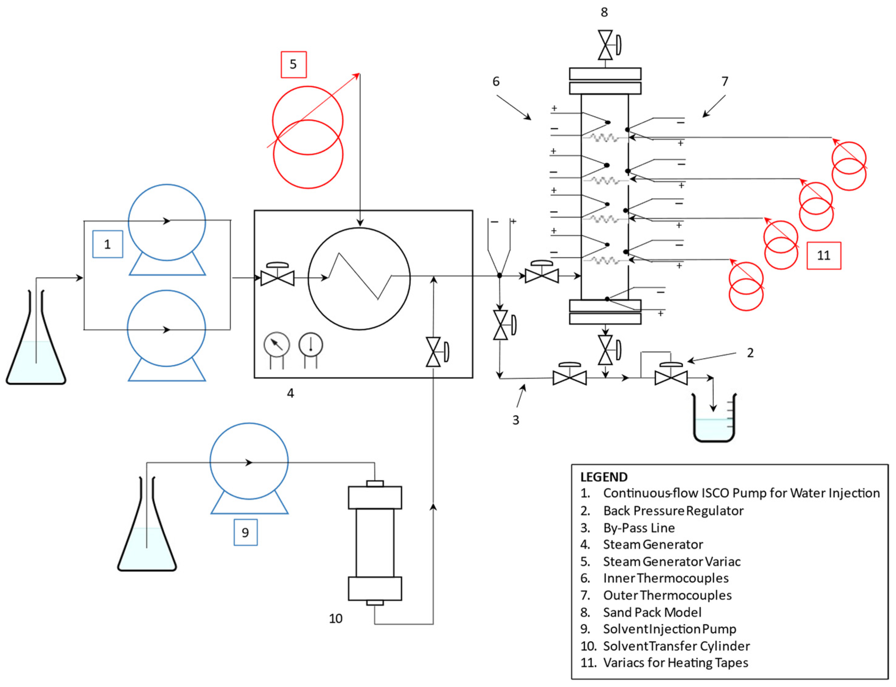
The completed system designed (
Figure 4) for this research was assembled.
3.3. Sand Pack Preparation
After assembling the lower end-cap on the cell and placing the four internal thermocouples, Ottawa sand was carefully introduced into the sand pack holder, whilst being compacted using a brass hammer to promote uniform settling and minimise void spaces. This sand selection was owing to its uniform particle size distribution, high purity, and well-rounded grain morphology. Upon completion of the filling process, the end-caps were secured, and axial stress was applied by progressively tightening the bolts. This was performed using an alternating cross-tightening pattern in conjunction with gentle hammer tapping to ensure consistent stress distribution. Subsequently, the assembled sand pack underwent CO2 flooding to displace air, followed by vacuum evacuation. The pack was then saturated with deionised water under a controlled back pressure of 200 psi, ensuring complete saturation and dissolution of any residual CO2 trapped within the pore space.
3.4. Porosity and Permeability Measurements
Darcy’s Law was applied to measure sand pack permeability with a water current under a fixed gravity head as:
The parameters are defined as follows: q denotes the volumetric flow rate (mL/s); A represents the cross-sectional area of the sand pack (cm2); μ is the dynamic viscosity of the water (cp); Δp corresponds to the pressure differential across the length of the sand pack (atm); L is the total length of the sand pack (cm), and k signifies the intrinsic permeability of the sand pack (darcies). This process offered a standard deviation of 2.88 Darcies for the sand pack utilised.
After measuring permeability, the bitumen saturation was developed with a preheated Long Lake sample by displacing water and establishing the initial oil saturation.
As the calculated sand pack bulk volume was 155 mL, for matrix volume determination, all thermocouples and fittings were placed on the sand pack, and subsequently, the water weight to fill it was measured. Sand weight and water weight were measured in each test.
After the air evacuation of the sand pack, the water volume was measured and taken as the pore volume. After measuring the water density at laboratory conditions (24 °C) using 10- and 25-mL pycnometers (1.00 g/mL), the pore and bulk volume were defined previously to calculate sand matrix porosity and the standard deviation of the sand packs (0.18%).
3.5. Oil Saturation
The experimental work employed dead oil sourced from Nexen’s Long Lake operation, originally recovered via the SAGD process. This bitumen, collected from the inlet separator, contained a substantial proportion of diluent, which was subsequently removed through vacuum distillation using rotary evaporators. To maintain uniformity in experimental conditions, a single large batch of processed oil was prepared, with its viscosity restored to that of the original Long Lake crude by reintroducing a measured quantity of the separated diluent. The final prepared oil was stored under frozen conditions until required for testing (
Table 1).
Initial oil saturation was developed vertically upwards to counter the effects of differential density between water and bitumen. At the same time, bitumen was warmed at 70 °C to allow it to flow easier into the sand pack model placing a heating tape around it.
During the oil flooding phase, the mass of the produced water was recorded, and the corresponding volume was assumed to equal the volume of oil present within the sand pack. The ratio of oil volume to the total pore volume was defined as the oil saturation, while the irreducible water saturation was determined as the ratio of the residual water volume to the pore volume. All SAGD and solvent-assisted SAGD experiments in this study were conducted using dead oil, with no initial gas saturation present.
Once porosity and permeability were measured, a first insulation layer was wrapped and subsequently outer thermocouples to each zone were installed to track the inner increase in temperature through four independent heating tapes ensuring the only source of heat remained the injected steam.
3.6. Multi-Component-Solvent Selection
In previous laboratory tests [
13], single-component solvents were assessed obtaining different performances regarding type and volume percentage. At the same time and considering that formation damage such as asphaltene precipitation can be promoted by the affinity of the solvent with certain hydrocarbon component chains, the composition of multi-component solvent can be a key parameter to avoid hydrocarbons’ components precipitation [
28].
Relatively heavier solvents, such as cracked naphtha and gas condensate—both evaluated as potential candidates for SA-SAGD applications—exhibit greater solubility in bitumen and may achieve superior dilution, provided they remain in a vaporised state within the steam chamber.
When implementing solvent-assisted SAGD, a thorough understanding of critical factors—including optimal solvent type, concentration, and operational strategy—is essential to maximise performance while mitigating any adverse effects on the reservoir and its properties. Among the solvents tested in this study was cracked naphtha, a multicomponent hydrocarbon blend comprising paraffinic, aromatic, and olefinic constituents, with its representative composition outlined in
Table 2. Its selection was informed by a detailed assessment of reservoir characteristics, operating conditions, and bitumen properties specific to the Long Lake project.
In this phase of this study, three high-pressure/high-temperature (HP/HT) SA-SAGD experiments were performed using a partially scaled linear physical model. Throughout each test, temperature, flow rate, and pressure were continuously monitored, while produced fluid samples were collected and analysed. In addition, post-test analysis of the porous matrix was conducted to evaluate process efficiency. The performance of each experiment was assessed based on key metrics, including vapour chamber growth rate, oil and water production rates, steam–oil ratio (SOR), and the residual oil saturation within the sand pack.
The second solvent investigated was gas condensate—a more volatile alternative to cracked naphtha—whose composition is detailed in
Table 3.
Due to their multi-component composition, cracked naphtha and gas condensate offer greater operational versatility than single-component solvents, enabling their use across a broader range of pressure conditions. In particular, gas condensate contains light-end fractions that remain in the vapour phase under typical SAGD conditions. These lighter components tend to migrate and accumulate at the upper regions of the steam chamber, thereby acting as a thermal barrier that mitigates heat loss to overlying strata and helps maintain chamber temperature. Moreover, these multi-component solvent mixtures are often compatible for blending with produced bitumen and are generally more cost-effective than their single-component counterparts.
It was important to strictly follow the protocols defined for this research to have consistent sand packing, permeability measurement, test and sample analysis procedures that deliver reliable and comparable results.
4. Testing Procedure and Sample Analysis
To ensure consistency and enable meaningful comparisons across all experimental runs, uniform conditions and protocols were rigorously maintained throughout this study. These included standardised parameters such as sand mesh size and packing methodology, sand pack geometry, preheating duration, operating temperature, steam injection rate, sampling frequency, and post-test analytical procedures. To establish a robust and reproducible framework, three preliminary trials were conducted to optimise these variables. A sand mesh range of 16–30 was selected as the most operationally efficient, balancing manageable experimental durations (approximately 9.5 h). This configuration facilitated consistent steam chamber development and sustained fluid production. Following the parameter optimisation, a series of three baseline SAGD experiments was executed to validate the performance and reliability of the apparatus and to generate reference data for subsequent evaluation of ES-SAGD performance.
4.1. Sand Pack Pressurisation
To reach injection conditions (steam at 207 °C and 1.585 MPa) before opening the inlet and outlet sand pack valves to start the injection, the heating tape around zone 1 was turned on at 70 °C and the steam was allowed to flow through the bypass line by keeping both of its valves open.
As soon as the temperature and pressure to start injection were achieved, the valves on the sand pack were opened and the ones on the bypass lines closed to allow the steam to come into the sand pack. The steam injection was developed at a 2 mL/min flow rate, recording the operational parameters in each timestep (15–20 min) until reaching a fixed injected volume of 20 hydrocarbon pore volumes (HCPV).
4.2. Sand Pack Depressurisation
To preserve the integrity of the experimental setup, the conclusion of the SAGD and ES-SAGD tests was executed through a carefully controlled shutdown procedure. Initially, the electrical power to both the preheater and steam generator was switched off while maintaining water flow to enable gradual cooling. The water flow rate was then methodically decreased and ultimately stopped once the preheater and steam generator temperatures reached a safe threshold of approximately 100 °C or below.
Throughout the cooling period, the domes of the back-pressure regulators were connected to the annulus via the control panel, providing protection to the sand-pack model against potential damage. Finally, the water pump was deactivated, and the depressurised sand-pack system was safely isolated from the injection and production lines.
4.3. Liquid Sample Analysis
The bitumen material balance and residual oil saturation within the sand pack were assessed through analysis of liquid samples obtained during the experiments, complemented by examination of solid samples extracted from the holder. The detailed methodology employed for this evaluation is outlined below.
4.3.1. SAGD Experiments
To use the Dean-Stark Distillation technique, each sample was added 30 mL of toluene to break the bitumen-water emulsion. After the two phases had settled down apart from each other, using a separatory funnel, the water was removed and the hydrocarbon phase and the remaining water, was distilled, hence calculating the amount of oil and water in each sample.
The Dean-Stark process was time-consuming because of the high-water volume in each sample; thus, to reduce the time for sample analysis, a technique based on solvent addition and measurement of the density of the separated solvent-bitumen mixture was developed. In this process, each sample was mixed with a fixed amount of toluene (30 mL), and after agitation in an ultrasonic water bath set at 60 °C, the hydrocarbon phase was separated to measure its density with a pycnometer. The toluene-bitumen density mixture can be related to the toluene density and bitumen density by:
being
ρm the density of the bitumen-toluene mixture (g/mL);
vt the volume fraction of toluene (%);
ρt the density of toluene (g/mL);
vb the volume fraction of bitumen (%), which is equal to (1 −
vt); and
ρb the density of bitumen (g/mL). The previous equation assumes an ideal solution; thus, several measurements were conducted by varying the toluene concentration in prepared samples.
An ideal mixture shows no considerable deviation from a linear relationship between density and concentration; therefore, the fraction volume of bitumen in the mixture was able to be determined from the measured mixture density. For this case, toluene was a fixed volume of 30 mL and thus the bitumen volume could be calculated.
4.3.2. SAGD Solvent Coinjection Experiments
When collecting the produced fluid in open sample vessels after the BPR, it was at the water boiling point and because of the high volatility of the solvent, most of the solvent evaporated during its collection. The open collection vessels were kept open while the sample cooled down to room temperature. As the remaining sample contained only bitumen and water, the analysis of the bitumen-water mixtures was carried out by applying the method of density described before, assuming the vaporisation of the solvent from the sample.
4.4. Solid Sample Analysis
After the sand pack was depressurised and cooled down, a visual inspection of the sand from each zone was carried out. All the matrix was weighed, and fluids were extracted by the Soxhlet method to calculate the remaining water and residual oil.
A sand matrix sample was placed into an extraction thimble, which was then positioned within the main chamber of a Soxhlet extractor. Toluene vapour ascended to the condenser, passing through the chamber containing the thimble. Upon reaching the condenser, the vapour cooled and condensed, subsequently dripping back into the Soxhlet chamber. Concurrently, water was distilled and separated from the toluene within a trap, enabling the toluene to be recycled and reused. The toluene continuously dissolved bitumen from the sand matrix, while water accumulated in the trap.
As warm toluene progressively dissolved bitumen from the sand grains inside the thimble, the solution collected in the distillation flask. This cycle persisted until toluene free of oil was observed dripping into the flask. The oil content was then calculated based on the measured weights of the original sand matrix, the water collected during the process, and the cleaned, dry sand. A material balance approach was employed to accurately quantify the separated quantities of bitumen, water, and sand.
5. Results and Discussion
A detailed evaluation of the produced fluids and samples obtained from the porous media was conducted to investigate the influence of cracked naphtha and condensate coinjection with steam on the efficiency of the SAGD process.
5.1. Base-Case SAGD
With this set goal, three preliminary tests of SAGD allowed for selecting a sand mesh 16–30 as the suitable option regarding test’s time (9.5 h approx.) to collect 20 fluid samples (each pore volume injected) at a 2 mL/min injection rate, providing a consistent steam chamber growing and a continuous production rate. After defining these parameters, a sand pack for Base-Case SAGD was prepared, tested and analysed, providing the following data (
Table 4).
A consistent steam chamber growth was observed throughout the test, although the temperature in zone four remained below 207 °C (steam injection temperature), unlike in the other three zones (
Figure 5).
This condition may have limited the enhanced bitumen drainage from Zone 1, potentially leading to a reduction in the ultimate recovery factor. Nevertheless, the advancement of the steam chamber into the third zone was clearly evidenced by both the analysed samples and the recorded temperature profiles.
Upon completion of the SAGD test, produced fluid samples were collected after each pore volume (PV) injection and subsequently analysed following established protocols for both solids and liquids. Residual oil saturation (S
or) was determined using two approaches: material balance calculations and direct measurement of the extracted sand samples. The resulting data are summarised in
Table 5. Although the values derived from both methods were comparable, the residual oil saturation measured via sand extraction tended to be slightly lower and was regarded as more representative of the system due to its direct origin.
Oil production proceeded at a consistent rate throughout the duration of the test. Analysis of the collected samples enabled the construction of a recovery factor (RF)—defined as the volume of bitumen recovered normalised by the hydrocarbon pore volume (HCPV)—plotted against the cumulative steam injected to evaluate process performance, as illustrated (
Figure 6). For clarity, a horizontal red dotted line marks the measured HCPV (mL), facilitating straightforward interpretation.
5.2. SA-SAGD (Cracked Naphtha Coinjection)
Building upon the reliable data obtained from the Base-Case SAGD test, subsequent experiments were initiated involving co-injection of multi-component solvents, beginning with cracked naphtha at a concentration of 5 vol%. In later tests, this concentration was incrementally increased to 10 and 15 vol%. Throughout these experiments, the same standardised protocols for sand pack preparation were meticulously maintained. Key properties of the sand packs utilised in these tests are summarised in
Table 6. The selected concentration range reflects common values reported in the literature and offers practical relevance for evaluating the solvents’ impact.
Upon injection at the sand pack inlet, cracked naphtha blended with the steam and was subsequently vaporised. The final temperatures observed in zones two, three, and four of the sand pack were consistently lower than those recorded in the Base-Case SAGD tests (
Figure 7a,
Figure 8a and
Figure 9a). Increasing the solvent concentration led to a reduction in residual oil saturation, with levels falling below 10% at a 15 vol% solvent concentration (
Figure 7b,
Figure 8b and
Figure 9b). Correspondingly, the cumulative steam-oil ratio (cSOR) exhibited a systematic decline as the solvent concentration was elevated.
The results derived from sand extraction and material balance calculations are presented in
Table 7. For cracked naphtha, the values obtained through both methods were closely aligned, although the material balance approach yielded slightly higher estimates.
5.3. SA-SAGD (Natural Gas Condensate Coinjection)
After using cracked naphtha, another multi-component solvent was tested. For this case, gas condensate at 5 vol% on a sand pack with properties mentioned in
Table 8.
In this test, the final temperatures recorded in sand pack zones two, three, and four were significantly lower than those observed in the Base-Case SAGD, as well as compared to the previous solvent test at the same concentration (
Figure 10a). The ultimate recovery factor achieved was 85.3%. The data from the measured samples are illustrated in
Figure 10b, while the residual oil saturations determined through sand extraction and material balance are summarised in
Table 9.
Both multi-component solvent mixtures investigated in this study exhibited a reduction in heat transfer to the upper section of the experimental cell. This observation highlights the necessity of properly adjusting the injection strategy and steam chamber growing to drain the upper part of the reservoir, minimising heat losses to overlying strata above the exploitable bitumen zone to improve the overall thermal efficiency of the SAGD process.
The general comparison for this research, including cracked naphtha and natural gas condensate coinjection together with the Base-Case, is presented (
Figure 11). The addition of cracked naphtha or gas condensate in conjunction with steam enhances the initial phase of the SAGD process by significantly lowering the viscosity of bitumen in the region between the well pair, thereby expediting the preheating period and accelerating steam chamber development. The final recovery factor was 23.3% OOIP higher with coinjection of the natural gas condensate, which is much better than cracked naphtha at this concentration.
The coinjection of multi-component solvents and steam in the SA-SAGD process resulted in higher incremental oil recovery compared to single-component solvent coinjection. This improvement is attributed to a more significant reduction in the SOR, enhancing the overall efficiency of the process [
42]. Increasing the solvent concentration made the SOR and cSOR decrease with both multi-component solvents (
Figure 12).
From the perspectives of cSOR, solvent formulations enriched with intermediate hydrocarbons—specifically iC5 to C6 at concentrations exceeding 18 mol%—demonstrated superior performance in reducing cSOR compared to formulations containing higher concentrations of heavier components —C7 to C10 at concentrations exceeding 8 mol%.
However, this behaviour is not linear for any of these solvents and compositions. The performance enhancement was better with gas condensate compared to cracked naphtha. Moreover, gas condensate showed even better results as per its performance at 5 vol%, which was better than cracked naphtha at 10 vol%. The incorporation of 15 vol% cracked naphtha resulted in the most effective performance, yielding the lowest residual oil saturation and the highest oil recovery rate observed in this study. Notably, the use of natural gas condensate also demonstrated strong performance, with substantial improvements in recovery efficiency.
While the initial coinjection of either solvent, cracked naphtha and natural gas condensate with steam, provides substantial benefits in terms of bitumen mobilisation, its advantages tend to diminish as the SAGD process progresses. Over extended coinjection periods, the incremental improvements in recovery become less pronounced, as shown after 10 PVI and beyond (
Figure 13).
The early-stage co-injection of multi-component solvents facilitated the rapid establishment of hydraulic connectivity between the SAGD injection and production wells, thereby accelerating the initial increase in bitumen production (
Figure 11). At this point, no significant differences were observed between the various concentrations of cracked naphtha; however, natural gas condensate yielded lower production rates initially. This trend shifted around three injected hydrocarbon pore volumes (IHPV), at which point natural gas condensate surpassed cracked naphtha, sustaining a notably higher oil drainage rate through the mid-phase of the tests.
While the efficacy of natural gas condensate gradually diminished over time, its influence remained measurable through the mid-phase before stabilising toward the experiment’s conclusion. In contrast, cracked naphtha co-injection demonstrated superior performance during the initial stages of the ES-SAGD process, but its mobilisation effect waned rapidly, remaining limited throughout the remainder of the test and consequently restricting its effectiveness during later recovery stages.
The compositional analysis reveals that the cracked naphtha sample contains hydrocarbons ranging from C4 to C7+, with a dominant C7+ fraction representing 71% of the total. In contrast, the natural gas condensate sample spans from C1 to C7+, but its heavier C7+ fraction comprises only 28.5%, while the lighter hydrocarbons (C4–C6) account for approximately 70%. The higher proportion of lighter components in natural gas condensate enhanced its efficiency, as these fractions exhibit superior volatility and mass transfer behaviour, which are beneficial for thermal and solvent-based recovery processes.
The application of gas condensate in SA-SAGD has demonstrated enhanced oil production rates and improved energy efficiency relative to cracked naphtha coinjection, indicating its potential as a more effective solvent for maximising recovery performance in solvent-assisted processes. In these systems, phase transitions of steam and solvent occur independently at their respective vapour pressures rather than at the overall injection pressure. Consequently, differences in partial vapour pressures result in variable condensation timings along the vapour–bitumen interface. These temporal disparities in condensation influence oil flow behaviour; notably, earlier condensation of the solvent facilitates a more effective reduction in bitumen viscosity and residual oil saturation. This process also mitigates the dilutive effects of water condensate and substantially enhances the mobility of the oil phase.
5.4. Uncertainty Analysis
An overall measurement uncertainty of approximately 3.5% was estimated for the volumetric data, as illustrated by the recovery factor curves. This cumulative uncertainty arises from several contributing factors, which are delineated below.
Temperature monitoring employed thermocouples with an uncertainty of ±2.0 °C across the operating range, and data were recorded with a resolution of ±0.1 °C. This measurement variability is reflected in the temperature profiles, particularly in zone 1. Data regarding temperature and pressure were recorded manually over intervals of approximately five minutes. As a result, temporal continuity was approximated to interpolate between readings.
To maintain the target steam injection rate of 2 mL/min, the system operated by alternating between two injection pumps, each with a maximum reservoir of 300 mL. This mode of operation induced transient flow instabilities during the switching events, introducing unsteady flow conditions within the sand pack. These instabilities disrupted the uniformity of the production rate and led to flow batching phenomena. Recovery factors were computed based on samples collected at each injected pore volume, where volumetric measurements carried an inherent instrument error of ±0.1 mL at the set flow rate.
All volume and mass measurements were subject to intrinsic limitations of the laboratory instruments (±0.1 mL for volumetric readings and ±0.01 g for weighing), in addition to potential user-induced variability. The resulting uncertainty, encompassing both systematic and random errors, was estimated at approximately 3.0%. Due to the length and complexity of each experiment, multiple tests could not be conducted for a full statistical analysis. Nevertheless, clear and strong trends are evident in the data.
6. Conclusions
For a specific reservoir and set of operational parameters, there exists an optimal window for solvent selection and concentration that maximises recovery efficiency. Injecting solvents at lower concentration ratios can effectively exploit the advantageous dilution effects while still retaining the thermal benefits provided by steam. Moreover, the results of this study indicate that strategically designed solvent blends may deliver superior performance compared to pure solvent injection under field-relevant conditions, providing a more balanced and synergistic enhancement to thermal recovery processes.
The results underscore the critical influence of the azeotropic behaviour exhibited by steam–solvent mixtures in governing the temperature at the vapour chamber interface, where the solvent interacts most actively with the in situ bitumen. This interfacial temperature, often markedly lower than the injection temperature of the steam–solvent blend, plays a decisive role in controlling both the rate of bitumen mobilisation and the overall thermal efficiency of the recovery process.
The phase behaviour of steam–solvent systems and its impact on SA-SAGD performance remains a complex and pivotal subject, necessitating thorough investigation. Due to its multifaceted nature, a rigorous and holistic approach is essential to elucidate the role of the solvent in enhancing recovery. This involves an integrated framework that combines phase behaviour modelling, interpretation of physical model experiments, numerical reservoir simulations, and insights drawn from field pilot evaluations.
It has also been observed that under lower-pressure operating regimes, the use of light hydrocarbon solvents may result in reduced incremental oil recovery in SA-SAGD applications. Nevertheless, the strategic formulation of multicomponent hydrocarbon blends—such as those found in commercially available diluents—offers significant promise for enhancing the efficiency and effectiveness of solvent-assisted thermal recovery.
The development of an optimal steam–solvent co-injection strategy is inherently multifactorial, influenced by the solvent’s dilution capacity, chemical compatibility with reservoir fluids—particularly concerning asphaltene stability—economic feasibility, market availability, incremental recovery potential, and the timeframe over which recovery gains are realised. In practical field applications, economic and logistical factors, including solvent pricing and supply chain limitations, often play a defining role in solvent selection and, by extension, the design of the injection protocol. Notably, the enhanced recovery kinetics enabled by light solvent co-injection can improve project economics by accelerating production timelines and reducing steam requirements.
In certain scenarios, deploying larger volumes of lower-cost, less efficient solvents may be economically justified, even if this entails accepting greater solvent losses. Accordingly, a comprehensive economic evaluation of any steam–solvent recovery scheme must consider the entire project lifecycle. This includes not only the upfront and operating costs but also potential revenue from solvent recovery and the overall return on investment.


