Abstract
The article discusses a regenerative heat exchange system for a solid oxide electrolyzer cell (SOEC) used in the production of green hydrogen. The heating system comprises four heat exchangers, one condenser heat exchanger, and a mixer evaporator. A pump and two throttle valves have been added to separate the hydrogen at an elevated steam condensation temperature. Assuming steady flow, a thermodynamic analysis was performed to validate the design and to predict the main parameters of the heating system. Numerical optimization was then used to determine the optimal temperature distribution, ensuring the lowest possible additional external energy requirement for the regenerative system. The proportions of energy gained through heat exchange were determined, and their distribution analyzed. The calculated thermal efficiency of the regenerative system is 75%, while its exergy efficiency is 73%. These results can be applied to optimize the design of heat exchangers for hydrogen production systems using SOECs.
1. Introduction
In the context of the increasing integration of intermittent renewable energy sources, such as wind and solar power, solid oxide electrolyzer (SOE) technology has the potential to play a pivotal role in stabilizing power grids, facilitating energy storage, and producing clean transportation fuels. The concept of the hydrogen economy involves the utilization of hydrogen as a carbon-free energy carrier. This signifies that it does not engender carbon emissions, such as CO2 or CO, during its conversion to water. It is important to note that hydrogen does not serve as a primary energy source in and of itself; rather, it functions as a means of transporting and storing energy [1,2,3].
The high efficiency potential of SOECs for H2 production has been confirmed in studies by Ni et al. [4], which analyze the most advanced SOEC technologies with a specific focus on ion-conducting electrolytes and electrodes. Hagen et al. [5] reached analogous conclusions regarding the potential escalation in the proportion of electricity derived from SOECs, juxtaposing electrolyte-supported cells with metal-supported cells functioning at temperatures of 650 °C. This comparison demonstrated that metal-supported cells exhibited superior performance, concomitant with reduced specific resistance and enhanced stability in their operation. A comparative analysis of three different technologies for electrolysis on board marine transport—namely, solid oxide (SOEC), proton-exchange membrane (PEME), and alkali-line electrolysis (AE)—shows that the cost of hydrogen (H2) produced by SOECs is cheaper than that produced by the other two technologies [6].
In [7], an analysis is conducted on a solid oxide electrolysis cell (SOEC) powered by a concentrating solar spectrum separator. The study finds that the presence of a greater number of solar spectra contributes to an increase in heat generation. A further study on the application of solar energy to drive SOECs involves an integrated thermal energy storage system, which has been demonstrated to reduce heat fluctuations by 75% and to achieve rapid optimization of the electrolysis process in real time [8].
The studies that are conducted with the objective of optimizing the H2 production process using a 3 kW high-temperature SOEC analyze the following stack parameters: voltage, power consumption, and the distribution of specific energy consumption on auxiliary equipment. As demonstrated in [9], the potential exists for the regulation of energy efficiency within the range of 60% to 100%, in addition to the management of a temperature variance of up to 100%. The utilization of an optimization model founded upon the heat balance of an SOEC with renewable sources resulted in the maximization of profit through the control of electrolysis current and input flow [10]. Utilizing a multiphysical approach and CFD analysis, a 10-cell SOEC was modeled and examined. The findings revealed that cross-flow enhanced H2 production and elevated thermal stress [11].
In addition to their capacity for hydrogen production, SOECs have also demonstrated a degree of flexibility in complex energy systems. Abousalmia et al. [12] integrated SOECs into a system comprising turbines, a pump, and an expansion vessel, thereby demonstrating its capacity to produce syngas from CO2 and water through co-electrolysis within the Allam–Fetvedt cycle for electricity generation.
It is noteworthy that high-temperature steam electrolysis can consume less energy if conditions are created for the most efficient possible recovery of waste heat. The systems of heat exchangers and electric heaters employed for the purpose of preheating the water can be classified as a type of Balance-of-Plants (BoP). These systems can be defined as a wide range of configurations of thermally connected systems for specific operating conditions [13]. Tanozzi et al. investigated a network of heat exchangers for a solid oxide fuel cell combined with a gas turbine with a view to minimizing the mass of the heat exchanger network [14]. The optimization of a network of heat exchangers is demonstrated in [15], with the aim of ensuring efficient autonomous operation of a high-temperature SOEC for hydrogen and oxygen. In their investigation, Mohammadi et al. examined an SOEC-specific heating system comprising heat exchangers, heaters, evaporators, and heaters, in which a compressed-air energy storage system integrated with a dish collector was employed [16]. The efficiency of the SOEC was analyzed in three connection modes: without a heat source, with a low-temperature light source, and with a high-temperature light source [17]. The present study investigates the performance of a system involving an SOEC for hydrogen production in combination with a solar–thermal photovoltaic cell and a heat recovery system [18]. The issue of enhancing the performance of a heating-power generation and residential system with SOECs has been addressed in [19]. A system of SOEC stacks with multiple components of thermodynamic systems has been the subject of study, from which 11 configurations have been selected from 72 proposed ones, which have been optimized for minimum external heat input [20]. As demonstrated in [21,22,23], enhanced energy efficiency and productivity metrics have been attained through the utilization of thermodynamic analyses and optimizations of closed heat exchange-cycle systems for SOECs.
A substantial body of research has been dedicated to the electrochemical characteristics of Elcogen’s commercial solid oxide cell stacks (SOCs), with findings indicating that they exhibit some of the best characteristics in terms of efficiency and overall performance [23,24,25].
Most of the studies that were examined focus on the parametric optimization of heat consumption in the preparation of inlet gases. Several studies have examined the possibility of returning some of the heat of the outlet gases from the SOEC back into the process. However, pressure has not been examined as a significant factor for thermodynamic process improvement.
The present study aims to analyze the thermodynamic parameters and optimize an energy heat exchange recovery system designed to power a standard 3 kW solid oxide cell stack (SOEC) from Elcogen (Helsinki, Finland). The results of the calculations are expected to be useful in the design of the heat exchange system, with the focus here being on whether the use of a pump is appropriate for hydrogen separation at higher temperatures. The novelty of this study is predicated on the possibility of recuperating exhaust heat energy by increasing fluid-flow pressure, thus reducing energy loss during phase change. It is hypothesized that this will enhance the efficiency of the system; this is a novel finding in the field. The ultimate objective is to achieve an enhanced system design at the conceptual level. The findings of the calculations are anticipated to be beneficial in the design of the heat exchange system, with the emphasis here being on determining the suitability of employing a pump for hydrogen separation at elevated temperatures. In general terms, the calculations are performed at the system level in order to facilitate a review of the proposed novel concept. Considering the findings of this study, subsequent actions are scheduled to encompass the conceptualization of designs and their validation through virtual prototyping. However, these aspects fall outside the scope of the present study.
2. Conceptual Synthesis of the SOEC Thermodynamic System with Heat Exchangers and a Pump
The heat exchange system of an SOEC is considered in which steady flow has occurred, i.e., all pipes and heat exchange systems are filled, and temperature changes and other thermodynamic processes repeat cyclically over time. The thermodynamic processes are illustrated by a temperature–entropy diagram (Figure 1).
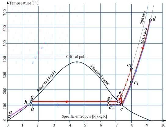
Figure 1.
Temperature–entropy diagram. The added lines show the constant pressure used.
It is assumed that the water reaching the SOEC has a mass of 1 kg and a pressure of 101.4 kPa (1 atmosphere or 1 bar). With this mass and pressure, the water is at points h, c, and d. In order to always have 1 kg in circulation, water with a mass of 0.6 kg and with an initial temperature of 20 °C (point a) is continuously added to the system. At point b, this water is heated to 100 °C and begins to evaporate. At point h, the saturated water with steam with a mass of 0.6 kg is mixed with the water returning from the SOEC, from which oxygen and hydrogen have already been separated, and its mass is 0.4 kg. At point c, the water has absorbed the necessary latent energy and has completely turned into superheated vapor. From point c to point d, the water increases its temperature to that required for the Elcogen E3000 SOEC, which can vary from 650 to 700 °C [26]. Here, this temperature is assumed to be 680 °C. The water has been converted into superheated steam at this temperature.
After the electrochemical processes take place in the SOEC stack, part of the steam decomposes into hydrogen and oxygen. The oxygen, with a mass of 0.525, is separated from the steam, passes through the electrolyte, and fills in the anode part of the SOEC. A mixture of steam and hydrogen, in a ratio of 0.6 kg and 0.075 kg, respectively, remains in the cathode chamber of the SOEC. To separate the hydrogen from the steam, the temperature of this gas mixture is lowered to 100 °C (point c) and, while still in a superheated vapor state, the pressure is increased by a pump to 200 kPa. In this state, point e on the T-s diagram shows that the temperature rises to 165 °C. The next thermodynamic state at point f, with a temperature of 120.2 °C, is reached after cooling, during which the heated-water flow transfers heat to the cold flow supplying the SOEC. After point f to point g, the steam begins to release its latent energy to the incoming flow, and at point g (120.2 °C, 200 kPa) it is completely condensed, and the hydrogen mixed in the steam is separated. From point g to h, the water passes through a throttle, after which its pressure drops from 200 kPa to 101 kPa and its temperature drops to 100 °C. At point h, the condensed water has turned into saturated steam and has mixed with the added saturated steam to repeat the closed cycle again. The oxygen obtained from the SOEC anode at a temperature of 680 °C is returned to the heat exchange system. The separated hydrogen, after condensation of the mixture of steam and hydrogen, is also fed into the heating system.
The inclusion of the pump at the saturated vapor line corresponding to point c (100 °C, 101.3 kPa) instead of at the saturation state boundary can also be achieved in two other scenarios. The first is at a higher temperature, in the single-phase region where there is only superheated vapor; for example, at point c1 (250 °C, 101.3 kPa), with a specific entropy of 8 kJ/kg·K. The second scenario is if the pump is turned on within the saturation state interval; for example, at point c2 (100 °C, 101.3 kPa), with a specific entropy of 6.5 kJ/kg·K and an enthalpy of 2393 kJ/kg. The first option is unfavorable because the pump will operate at high temperatures, but in the second option, the pump will operate in the smallest temperature range with a saturated mixture of steam and water.
The exact values of temperature, pressure, specific entropy, and specific enthalpy were determined using tables of thermodynamic properties of water and steam [27] and are shown in Table 1.

Table 1.
Temperature, pressure, specific enthalpy, and specific entropy of characteristic points of the heating system for water and steam.
3. Structure of the Heat Exchange System for an SOEC with Increased Pressure
The structure of the SEOC heat exchange recovery system with a pump is shown in Figure 2. Initially, water with a mass of 0.6 kg enters from point 1 at an ambient temperature of = 20 °C into Heat Exchanger 1 (HE1), where it exchanges its heat with the hydrogen coming from Throttle 1 (T1). As mentioned above, for point g in the Condenser–Heat Exchanger (CHE), the steam from the H2O + H2 mixture condenses at 120.212 °C and a pressure of 200 kPa. The hydrogen separated from the condensed vapor at point 11 has a temperature of = 120.212 °C and is separated through Throttle 2 (T2), where at point 2, its pressure has dropped to 101.3 kPa. From the condition for the conservation of specific entropy, according to data from [26] and by linear interpolation, this is calculated as = 71.6608 kJ/kg·K at 120.212 °C. Assuming that the thermodynamic cycle is ideal and the pump and both throttles are isentropic for the same entropy at 101.3 kPa, the corresponding temperature of = 51.34 °C is found. At point 6, the temperature of the hydrogen produced is assumed to be = 20 °C. After HE1, at point 3, the water with temperature enters Heat Exchanger 2 (HE2). At point 5, the temperature of the produced oxygen is assumed to be equal to that of the environment, i.e., = 20 °C.
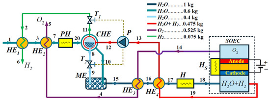
Figure 2.
Structure diagram of the regenerating heat system layout: HE1—Heat Exchanger 1; HE2—Heat Exchanger 2; PH—Preheater; CHE—Condenser–Heat Exchanger; ME—Mixer Evaporator; T1—Throttle 1; T2—Throttle 2; P—Pump; HE3—Heat Exchanger 3; HE4—Heat Exchanger 4; H—Heater; Hs—SOEC Heater.
HE2 uses the oxygen separated from the SOEC, which has transferred part of its energy to Heat Exchanger 3 (HE3). According to preliminary approximate calculations, the remaining energy of the oxygen at point 4 is not sufficient to heat the water at point 7 to a temperature of 100 °C, and part of the latent energy is added to reach the enthalpy at point h (Figure 1). This requires the addition of a Preheater (PH) to the heating system structure, through which the saturated steam state corresponding to point g of the T-s diagram at point 20 of the structural diagram can be reached. With an unknown temperature after point 7, the water is reheated in the CHE by the returned mixture of steam and hydrogen at elevated pressure. According to Figure 1 and Table 1, after the pump (P) at point 12, the mixture of steam and hydrogen should have a temperature of = 165.39 °C. The output temperature of the CHE should be equal to 120.212 °C if the water in the H2O + H2 gas mixture has reached the saturated vapor state. The same temperatures should also be present in the outgoing water flow and hydrogen flow . If the heat exchange in the CHE does not have the necessary energy to reach the saturated vapor state, then temperatures and will be in the range, i.e., (120.2 °C, 165.39 °C).
After Throttle 2 in Figure 2, it is evident that the pressure of the condensed water in the CHE decreases at constant entropy; therefore, the temperature of the steam flowing out of Throttle 2 at point 9 is =100 °C. The additionally heated water flow in the CHE at point 10 has an unknown temperature , at which point it enters the Mixer Evaporator (ME). The output water flow of the ME at point 15 enters Heat Exchanger 3, where it receives heat from the oxygen output flow of the SOEC, which has a temperature of = 680 °C at point 14. At point 16, the water heated by HE3 enters Heat Exchanger 4 (HE4) to receive heat from the mixed stream of steam and hydrogen exiting the SOEC at a temperature of 680 °C. Heaters H and Hs serve to raise the temperature of the steam obtained at point 17 to 680 °C, thus preparing it for entry into the SOEC at point 18.
Table 2 shows the data for the characteristic points at which the temperature and pressure change, as well as the actual and forecast temperature values.
Table 2.
Data on the characteristic points of the heating system.
Since the solubility of hydrogen in water is negligible, it is generally accepted that the two substances should be considered separately and independently of each other when mixed.
4. Energy Analysis and Formulation of an Optimization Problem for the Heat Exchange System
The thermal balance for one of the elements of the heat exchange system can be represented as follows [30]:
where is the heat transferred to the heated fluid per unit time in W; and are the average specific heat at constant pressure of the heating and heated fluids, respectively, in J/kg·K; and are the mass flow rates of the heating fluid and the heated fluid in kg/s; and are the inlet and outlet temperatures of the heated fluid; and are the inlet and outlet temperatures of the heating fluid in °C; and is the heat exchange efficiency.
The heat (Joules) which is transferred in a specific period of time in an ideal steady-flow and periodic regime can be expressed as follows:
where and are the masses of the heating fluid and the heated fluid that flows during the period under consideration.
Specifically, for the structure shown in Figure 2 at known temperatures , , and , the thermal balance of HE1 is given by the equation
from where the temperature at point 3 is expressed as
where = 0.95 is the accepted value of the efficiency of heat exchanger HE1 [22], = 0.075 kg is the mass of hydrogen, = 0.6 kg is the mass of the added water, and =14,882.64 J/kg·K is the average value of the isobaric heat capacity of hydrogen calculated for temperatures and according to the data in Table 2. For the average value of the isobaric heat capacity of water in the first iteration, ≈ 4184.8 J/kg·K is accepted. The exact value of is not yet known because the temperature is unknown. Iterative calculations are used to determine this specific capacity. The steps of these iterations are as follows: Using Formula (4) with the approximate value of , a temperature = 33.23 °C is calculated. Through linear interpolation, = 4179.35 J/kg·K is specified. Again, using Formula (4), a temperature of = 33.25 °C is calculated; the difference is found and compared with the permissible difference = 0.025 °C. Since the condition is satisfied and, upon further refinement of , its change is in the third digit after the decimal point, the calculated is accepted as the value of .
Since the procedure for determining the average specific heat capacity and the calculated temperature is used repeatedly, a special procedure has been created in Maple 16.
To determine the average values of heat capacities, data from certified reference books [28,29,30] should be used, and for water (steam), it will be necessary to additionally check whether it is in a single or saturated region. Figure 3a shows the graphs of the isobaric specific heat capacities of oxygen, water at a pressure of 101.3 kPa, and water at 200 kPa, while Figure 3b shows the graph of the specific heat capacity of hydrogen taken from the cited reference books.
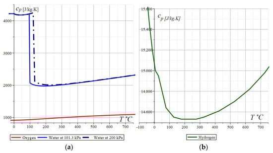
Figure 3.
Graphical presentation of isobaric specific heat capacity of: (a) oxygen, water at 101.3 kPa, and water at 200 kPa; and (b) hydrogen.
These graphs show that isobaric heat capacities cannot be considered to be constant values. Calculations are complicated by the fact that the data must be adjusted to the pressure of the respective system. This process can be time-consuming and lead to errors if each value is copied from the respective reference book. To address these challenges, the data from the reference books have been entered as arrays into the Maple 16 program. A special procedure has been created that selects the appropriate array depending on the type of fluid and pressure. At a given temperature, which, in general, does not match the data in the reference books, the procedure selects the closest higher and lower temperature values and calculates the desired average value of the specific isobaric heat capacity using a linear calculation (see Supplementary Material S1).
The thermal balances of the end of the Preheater (PH) must comply with the requirement that the inlet stream (points b and h in Figure 1) must have reached the boiling temperature of = 100 °C and be in a state of saturated steam at point h that corresponds to an enthalpy of = 573.283 kJ/kg (Table 1). Since the energy of HE2 cannot be insufficient, an intermediate enthalpy has been introduced for which the constraint is valid:
This intermediate enthalpy is used to express the energy of HE2:
whereby HE2 must be provided in order to achieve an intermediate state of saturated steam between points b and h. If the intermediate enthalpy is known, the Preheater must add the energy
From the above expressions, it can be seen that in the boundary cases at , the PH will have to add all the energy for steam saturation, while at , the PH becomes redundant. From these considerations, it can be concluded that one of the goals of heat exchange system optimization is to minimize the difference
where .
Given these assumptions for the complete thermal equilibrium of HE2, providing simultaneously a temperature of = 100 °C, 373.15 K, and the intermediate enthalpy , the following can be written:
where is unknown, but it is assumed that ≈ 320 °C to calculate an approximation of ≈ 959.13 J/kg·K as the initial value of the average isobaric heat capacity of steam for points 4 and 5; = 0.525 kg is the mass of oxygen obtained from the SOEC; = 3169.455 J/kg·K; and = 0.95 is the efficiency of the HE2.
The thermal balance of CHE can be written as
where ≈ 2056.829 J/kg·K at an assumed forecast temperature of ≈ 110 °C, = 2675.57 kJ/kg·K is the enthalpy of steam for the saturation line at point c (Figure 1), = 0.95 is the efficiency of the CHE, = 0.075 kg is the mass of the incoming hydrogen mixed with the steam from the SOEC, and = 2,202,150 J/kg is the specific latent heat of vaporization at 120.2 °C and 200 kPa.
The temperatures , , and here are known and given in Table 2, so from Equation (9), the unknown temperature can be expressed as
After applying the iterative procedure described above, the following result was obtained: = 103.52 °C at a specified = 2067.914 J/kg·K.
For the heat balance of the ME, it should be noted that for the mixed flow at point 15, the inlet steam flow at point 10 heats the flow entering through point 9 ( = 100 °C), from which it follows that
From this equation, the temperature is calculated using the formula
The iterative procedure for determining the average heat capacities was applied again, and the following values were obtained: = 110.01 °C, = 2056.81 J/kg·K, and = 2050.97.
The heat balance for HE3 leads to the equation
where = 1 kg is the mass of steam entering the SOEC, and = 0.95 is the efficiency of HE3. Since in (14), the temperatures and are unknown, the average values of the heat capacities and are calculated for predicted approximate temperatures of = 680 °C, ≈ 320 °C, and = 118 °C, and their initial values of the specific heat capacities are calculated as = 1041.72 J/kg·K and = 2004.34 J/kg·K.
The thermal balance of HE4 can be written as
where = 0.95 is the efficiency of HE4, = 2167.53 J/kg·K is the predicted average isobaric heat capacity of steam for points 13 and 19, and = 14,719.81 J/kg·K is the average isobaric heat capacity of hydrogen for points 13 and 19.
In Equation (15), there are two unknown temperatures, and , and although their difference can be expressed, the equation cannot be solved with the necessary accuracy because, if the difference is known, the values of the temperatures and the resulting average heat capacities cannot be calculated.
In order to find the optimal distribution of temperatures, from the Equation (15), only the temperature is expressed in the form
Equation (9) also expresses the temperature :
After equating (16) and (17), the following equation is obtained:
which, once solved with respect to , leads to
Equation (9) is also solved with respect to :
Equating the results from (19) and (20) leads to the equation
This equation can be considered as an optimization constraint, in which the components of the optimization vector are the temperature and the intermediate enthalpy at a defined objective function:
where the first term of the objective function is the energy of the Preheater (PH), and the second is the energy of the Heater (H), and = = 0.98 are the efficiency of the PH and H.
In addition to Equation (21), the following inequalities are added to the additional constraints:
5. Solving the Optimization Problem and Determining the Quality Parameters of the Heating System
The optimization function (22) is linear, but due to constraint (21) and the need to specify the average heat capacities , , , , , , , and , which are functions of temperature, the problem cannot be solved using linear optimization methods. One of the possible methods for calculating the heat capacities, applied here, is through successive iterations, but for this purpose, the temperatures , , and must be known. Since these temperatures have not yet been calculated, their initial forecast values are accepted, which are refined during the optimization procedure. The initial forecast values of the heat capacities for these three temperatures and for the others involved in the calculations are given in Table 3.
Table 3.
Forecasting initial values of middle initial isobaric heat capacities.
Despite the iterative calculations, the optimization constraint (21) can be expressed in terms of temperature and substituted into the objective function (22). In this way, the optimization function is expressed only by the intermediate enthalpy , but it should be noted that this function also includes the average isobaric heat capacities, which are functions of the nondetermined temperatures.
To solve the optimization problem, it is assumed that the optimization function is a continuous function and is calculated for 1000 values by varying the intermediate enthalpy . The result obtained is shown in Figure 4. From the three-dimensional curve, it can be concluded that function (22) is continuous, and its minimum can be determined by varying the step.
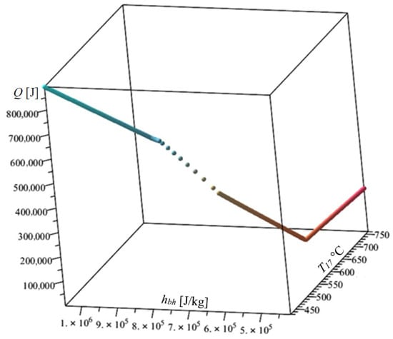
Figure 4.
Determination of the optimal values of the temperature and the intermediate specific enthalpy .
The graph in Figure 4 shows that the minimum value of the objective function (22) = 844.8329 J was obtained at the values of the optimization variables = 565,675.2667 J/kg·K and = 619.6798761 °C. The data for all the initial and optimized temperatures are given in Table 4.
Table 4.
Initial and optimized values of the temperatures.
To evaluate the sensitivity of the optimization function with respect to the key parameters , , , and , their sensitivities , , , and in percentages are defined as follows:
where , , , and are the optimal values of the key parameters , , , and .
These sensitivities are calculated for an interval of the objective function from to , and the obtained results are presented in Figure 5. The graphs show that after , all the sensitivities increase linearly. The sensitivity of is associated with the highest gradient. The sensitivities of and are almost the same, and the sensitivity of has the lowest gradient. These results show that to guarantee the obtained minimum of the objective function, the greatest efforts must be made to first ensure the accuracy of the temperature and then of and the enthalpy .
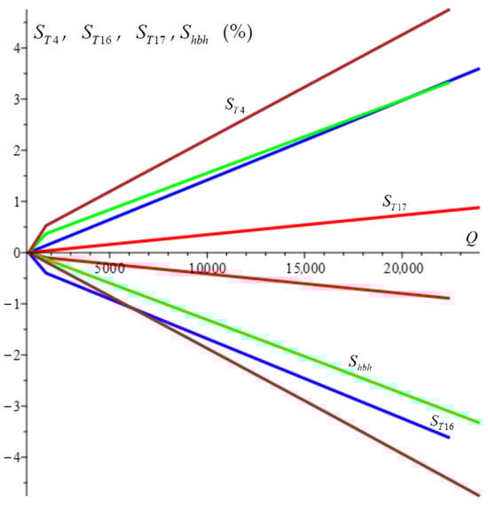
Figure 5.
Sensitivities , , , and in percentages of the optimization parameters , , , and with respect to the objective function.
The results also demonstrate the fast convergence of the optimization method with respect to the key parameters.
For the purposes of engineering analyses and applications, the results obtained can be considered satisfactory. From a mathematical point of view, the task can be solved, for example, using nonlinear programming methods, which would ensure higher accuracy. Such methods are expected to be included in future studies after the final selection of the heat exchange system structure.
With the parameters of the recuperation system obtained in this way, in addition to the optimized total consumption of PH and H, the energy of the pump and the electrical energy consumed by the SOEC during the chemical decomposition of water must be added to the energy consumption.
According to data from [31] for the SOEC Elcogen Elcostack model E3000, the efficiency is = 3.2 kWh/Nm3, which is the electrical energy required to produce one normal cubic meter (at 0 °C and 1 atmosphere) of hydrogen. Since 1 Wh = 3600 J, it can be assumed that for one Nm3, the electrolyzer cell consumes = 11,520 kJ. For the amount of hydrogen = 0.075 kg considered here, a volume of ≈ 0.834 Nm3 is found, or for this amount, the actual electrical energy consumed will be = 9707.68 kJ.
According to the same data [31], the volume flow rate of the SOEC Elcogen Elcostack model E3000 is = 3 Nm3/h, which is converted to a mass flow rate of 0.26964 kg/h, or, in SI, the mass flow rate of the cell is = 7.49 × 10⁻⁵ kg/s. Assuming that the volumetric flow rate of the steam is also 3 Nm3/h, which is equivalent to 0.000833 Nm3/s, and at a density of vapor of 1 kg/m3, the vapor flow rate is obtained as = 0.00125 kg/s. Considering that the SOEC outputs a mixed gas consisting of vapor and hydrogen in a ratio of 0.4:0.075, the equivalent mass flow rate of the mixed gas can be calculated as = 0.00106446 kg/s. The rate of the pump work in this case can be calculated by
from which it is calculated that = 133.153. Here, and are the enthalpies at points e and c from Figure 1 and Table 1.
The steady-state cycle period can be roughly figured out from the performance of the SOEC being studied, which, according to [31], is 3.0 Nm3/h or 0.27 kg/h, from which = 0.075/0.27 = 0.033 h = 118.8 s. Then the work of the pump for one steady-state period is = 15,818.58 J.
Ignoring the heat transfer between the outlet surface of the heat exchangers and the surrounding for the input energy [32] of a unit can be determined with the help of the formula
where is the mass of the flow, and and are the enthalpies of the end and the beginning of the heating process. These input energies are calculated in the optimization program after all reference data [28,29,30] have been entered and procedures have been created for calculating data that do not match the tabulated values using linear interpolation.
The optimized temperatures obtained for each unit of the system and their corresponding parameters in accordance with Formula (25) are shown in Table 5.
Table 5.
Gained energy of the heat regenerating system.
The distribution of the energy gained from the regenerating system is shown in Figure 6. As can be seen from the graph, Heat Exchanger 4 accounts for the maximum share of 63% of the energy produced, while Heat Exchanger 3 and Heat Exchanger 1 contribute 0.13% and 0.79% of the energy, respectively. ME also has a relatively small share at 0.19%, but its main task is to maintain the saturated steam state when mixing the two flows with approximately similar temperatures by varying the step.
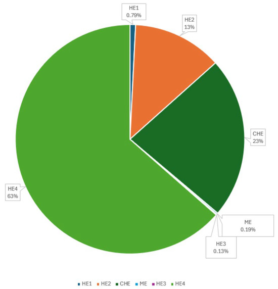
Figure 6.
Distribution of the gained energy between different units of the regenerating system.
With regard to the distribution of gained energy, it can be said that the task has not been solved well, and this is expected to be the next step in optimization, which will be solved in the future. In order to optimize the distribution of energy among the various modules, it is necessary to investigate structural changes in the heat exchange system. For example, a suitable option is to merge the low-temperature heat exchangers HE1 and HE2. It is also advisable to discuss the option of adding low-temperature inlet flows to HE4 and HE3.
The energy consumed in the case under consideration is the sum of the energies of PH, the H pump, and the energy in the electrolyzer for the electrochemical decomposition of water. The total energy consumed by the Preheater and Heater, = 185,230.7489 J, is obtained from the solution of the optimization task. The pump consumes work = 15,818.58 J, and the actual electrical energy consumed by the electrolyzer cell was obtained as 9707.68 kJ. These data are given in Table 6, and the distribution of the energy consumed when the electrolyzer is switched off is given in Figure 7a, while the total energy consumed is given in Figure 7b. The data on energy consumption are shown in Table 6.
Table 6.
Energy consumption of external sources.
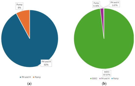
Figure 7.
Distribution of the consumed energy between different units of the regenerating system: (a) without energy consumption by the SOEC; (b) with energy consumption by the SOEC.
The energy previously introduced into the heating system can be calculated approximately as
from which we obtain = 3,634,619.494 J.
The thermal efficiency of the system is calculated using the ratio
and is determined to be = 0.75.
The exergy efficiency of the heating system can be calculated using the formula
from which it is calculated that =0.73.
The results obtained in terms of efficiency can be considered satisfactory when compared to other similar systems. There are several publications in which higher efficiencies have been reported, such as the one by AlZahrani A. et al. [15], who attained values of 79.24% and 77.62% for energy and exergy efficiency, respectively, with similar regenerative systems. In other studies, energy efficiency values of 56% [33,34] or 60% [35] have been reported.
6. Discussion
The obtained minimum of the objective function confirms the hypothesis of the possible separation of hydrogen from steam in regenerative heat exchange systems based on SOECs. At the same time, the lack of sufficient latent energy in the inlet flow at 100 °C necessitates the addition of a preheater to the structure. This new structural unit increases the energy consumption of the heat exchange system and reduces its thermal efficiency.
The main subject of discussion here is the possibilities for reducing the energy consumed by the preheater. One way is to increase the pump pressure. This will lead to less latent energy in the outlet stream and will increase the pump’s electrical energy consumption. A hypothetical option is to increase the pump pressure until the critical point of water is reached at 22.064 MPa. In this case, the latent energy of the outlet stream will be zero, and separation will occur immediately after reaching the pressure, but this high pressure is not suitable for engineering reasons.
Another possible way to influence the superheater consumption is to change the pump starting point in the temperature–entropy diagram (Figure 1). If the pump is switched on in the saturated steam region at low pressure—for example, at point c2 (Figure 1)—the temperature balance will change, but the pump’s energy consumption will remain the same as at point c. In this variant, the pump will operate at a lowest temperature of 120 °C, but the unused enthalpy from point b to h will again require a superheater.
7. Conclusions
A detailed analysis and optimization of an original heat regeneration system for a solid oxide electrolysis cell used to produce green hydrogen has been conducted. The hypothesis concerning the increase in pressure of the gas flow emanating from the SOEC cathode, a mixture of steam and hydrogen, has been corroborated. It has been established that an increase in pressure results in the condensation of water within the gas mixture, leading to the separation of hydrogen at temperatures in excess of 100 °C.
The thermodynamic studies demonstrate that, in accordance with the anticipated decline in latent energy during the condensation of steam from the SOEC stream, a proportion of the latent energy inherent in the water stream entering the SOEC cannot be recovered from the regeneration system. The implementation of an electrically powered preheater within the heat exchange structure is imperative. The energy balance of the heat exchange system has been taken into consideration, and the introduction of a preheater has been implemented. The purpose of this is to add energy to the incoming steam of the electrolyzer.
The distribution of temperatures in the heat exchangers and other modules of the regenerative heat exchange system is achieved through numerical optimization, wherein the objective function is formulated as the minimum energy of the preheater and heater. The solution to this problem is contingent upon identifying the optimal temperature distribution of the separate units.
The quantity of energy gained by each unit of the heat exchange system is determined, and its distribution is then analyzed. The thermal and exergy efficiency of the system are the focus of the present study, and the relevant calculations are presented herein.
The sensitivity of key parameters to the objective function has been investigated. The parameters that demonstrated the highest degree of sensitivity have been identified, and measures have been specified that must be observed in order to guarantee the minimum value of the objective function. Sensitivity studies also show that the optimization method has stable convergence.
Overall, the study indicates that there is still scope for structural and temperature optimization. The distribution of energy between the various heat exchange units could be made more efficient. The selection of an appropriate thermodynamic state of the system from which to increase the pressure of the gas mixture of steam and hydrogen has the potential to optimize the heating system.
Supplementary Materials
The following supporting information can be downloaded at: https://www.mdpi.com/article/10.3390/en18164424/s1, Mape program source S1: SOEC heating system calculation.
Author Contributions
Conceptualization, G.T., T.T., and K.K.; methodology, K.K. and T.T.; software, T.T.; validation, G.T. and K.K.; formal analysis, T.T.; investigation, T.T. and G.T.; resources, G.T.; data curation, G.T.; writing—original draft preparation, T.T.; writing—review and editing, G.T. and K.K.; visualization, T.T.; supervision, G.T.; project administration, G.T.; funding acquisition, T.T. and K.K. All authors have read and agreed to the published version of the manuscript.
Funding
This research was funded by the Europefan Union—NextGenerationEU, through the National Recovery and Resilience Plan of the Republic of Bulgaria, project No BG-RRP-2.004-0005.
Data Availability Statement
The data are contained within the article.
Conflicts of Interest
The authors declare no conflicts of interest.
Abbreviations
The following abbreviations are used in this manuscript:
| Isobaric specific heat capacity for fluid of type at point of the heating system | |
| Average isobaric specific heat capacity for fluid of type at points and of the heating system | |
| Energy of the SOEC for the steady-state period | |
| Specific enthalpy at point of the heating system | |
| Latent heat energy of vaporization or condensation at pressure | |
| Mass of the periodically added cold water | |
| Mass of the hydrogen | |
| Mass of the oxygen | |
| Mass of the vapor | |
| Mass of the returned vapor plus added vapor | |
| Mass flow rate | |
| Specific entropy at point of the heating system | |
| Temperature at point of the heating system | |
| Ambient temperature | |
| Steady-state period | |
| The rate of the heat of a flow | |
| Thermal energy of unit U of the heating system | |
| Volume flow rate | |
| Rate of the pump work | |
| Thermal efficiency | |
| Exergy efficiency | |
| Efficiency of unit U of the heating system |
References
- Armaroli, N.; Balzani, V. The Hydrogen Issue. ChemSusChem 2011, 4, 21–36. [Google Scholar] [CrossRef] [PubMed]
- Penner, S.S. Steps toward the Hydrogen Economy. Energy 2006, 31, 33–43. [Google Scholar] [CrossRef]
- Bockris, J.O. A Hydrogen Economy. Science 1972, 176, 1323. [Google Scholar] [CrossRef] [PubMed]
- Ni, M.; Leung, M.; Leung, D. Technological Development of Hydrogen Production by Solid Oxide Electrolyzer Cell (SOEC). Int. J. Hydrogen Energy 2008, 33, 2337–2354. [Google Scholar] [CrossRef]
- Hagen, A.; Caldogno, R.; Capotondo, F.; Sun, X. Metal Supported Electrolysis Cells. Energies 2022, 15, 2045. [Google Scholar] [CrossRef]
- Elrhoul, D.; Naveiro, M.; Romero Gómez, M. Thermo-Economic Comparison between Three Different Electrolysis Technologies Powered by a Conventional Organic Rankine Cycle for the Green Hydrogen Production Onboard Liquefied Natural Gas Carriers. J. Mar. Sci. Eng. 2024, 12, 1287. [Google Scholar] [CrossRef]
- Lang, S.; Yuan, J.; Zhang, H. Optimally Splitting Solar Spectrums by Concentrating Solar Spectrums Splitter for Hydrogen Production via Solid Oxide Electrolysis Cell. Energies 2024, 17, 2067. [Google Scholar] [CrossRef]
- Liu, H.; Shuai, W.; Yao, Z.; Xuan, J.; Ni, M.; Xiao, G.; Xu, H. Optimization of Solid Oxide Electrolysis Cells Using Concentrated Solar-Thermal Energy Storage: A Hybrid Deep Learning Approach. Appl. Energy 2025, 377, 124610. [Google Scholar] [CrossRef]
- Chen, Y.; Wu, X.; Hu, H.; Zhang, J. System Level Performance Analysis and Parameter Optimization of Hydrogen Production Based on Solid Oxide Electrolytic Cell. Appl. Energy 2023, 347, 121329. [Google Scholar] [CrossRef]
- Wu, Z.; Si, Y.; Li, S.; Ma, L.; Gao, M. Optimization Method for Economical Operation of SOEC Considering Thermal Balance Efficiency Characteristics. In Proceedings of the 2022 4th International Conference on Power and Energy Technology (ICPET), Beijing, China, 28–31 July 2022; IEEE: Piscataway, NJ, USA, 2022; pp. 698–704. [Google Scholar]
- Wang, H.; Xiao, L.; Liu, Y.; Zhang, X.; Zhou, R.; Liu, F.; Yuan, J. Performance and Thermal Stress Evaluation of Full-Scale SOEC Stack Using Multi-Physics Modeling Method. Energies 2023, 16, 7720. [Google Scholar] [CrossRef]
- Abousalmia, A.; Karagoz, S. Design and Simulation of an Integrated Process for the Co-Production of Power, Hydrogen, and DME by Using an Electrolyzer’s System. Energies 2025, 18, 2446. [Google Scholar] [CrossRef]
- Jeong, K.; Hong, J.; Kim, D.; Ji, J. SOFC-0205—Design and Optimization of a Solid Oxide Electrolysis Cell System and Its Behavior Under Load Following Conditions. Available online: https://ecs.confex.com/ecs/sofc2025/meetingapp.cgi/Paper/206073 (accessed on 10 June 2025).
- Tanozzi, F.; Sharma, S.; Maréchal, F.; Desideri, U. 3D Design and Optimization of Heat Exchanger Network for Solid Oxide Fuel Cell-Gas Turbine in Hybrid Electric Vehicles. Appl. Therm. Eng. 2019, 163, 114310. [Google Scholar] [CrossRef]
- AlZahrani, A.A.; Dincer, I. Modeling and Performance Optimization of a Solid Oxide Electrolysis System for Hydrogen Production. Appl. Energy 2018, 225, 471–485. [Google Scholar] [CrossRef]
- Mohammadi, A.; Mehrpooya, M. Techno-Economic Analysis of Hydrogen Production by Solid Oxide Electrolyzer Coupled with Dish Collector. Energy Convers. Manag. 2018, 173, 167–178. [Google Scholar] [CrossRef]
- Cui, T.; Zhu, J.; Lyu, Z.; Han, M.; Sun, K.; Liu, Y.; Ni, M. Efficiency Analysis and Operating Condition Optimization of Solid Oxide Electrolysis System Coupled with Different External Heat Sources. Energy Convers. Manag. 2023, 279, 116727. [Google Scholar] [CrossRef]
- Daneshpour, R.; Mehrpooya, M. Design and Optimization of a Combined Solar Thermophotovoltaic Power Generation and Solid Oxide Electrolyser for Hydrogen Production. Energy Convers. Manag. 2018, 176, 274–286. [Google Scholar] [CrossRef]
- Park, Y.J.; Min, G.; Hong, J. Operational Guidelines for a Residential Solid Oxide Fuel Cell-Combined Heat and Power System with an Optimal System Layout Design. Energy Convers. Manag. 2021, 246, 114666. [Google Scholar] [CrossRef]
- Min, G.; Park, Y.J.; Hong, J. Thermodynamic Analysis of a Solid Oxide Co-Electrolysis Cell System for Its Optimal Thermal Integration with External Heat Supply. Energy Convers. Manag. 2020, 225, 113381. [Google Scholar] [CrossRef]
- Min, G.; Choi, S.; Hong, J. A Review of Solid Oxide Steam-Electrolysis Cell Systems: Thermodynamics and Thermal Integration. Appl. Energy 2022, 328, 120145. [Google Scholar] [CrossRef]
- Wang, F.; Wang, L.; Ou, Y.; Lei, X.; Yuan, J.; Liu, X.; Zhu, Y. Thermodynamic Analysis of Solid Oxide Electrolyzer Integration with Engine Waste Heat Recovery for Hydrogen Production. Case Stud. Therm. Eng. 2021, 27, 101240. [Google Scholar] [CrossRef]
- Ploner, A.; Hauch, A.; Pylypko, S.; Di Iorio, S.; Cubizolles, G.; Mougin, J. Optimization of Solid Oxide Cells and Stacks for Reversible Operation. ECS Trans. 2019, 91, 2517–2526. [Google Scholar] [CrossRef]
- Lang, M.; Lee, Y.S.; Lee, I.S.; Szabo, P.; Hong, J.; Cho, J.; Costa, R. Analysis of Electrochemical Degradation Phenomena of SOC Stacks Operated in Reversible SOFC/SOEC Cycling Mode. J. Electrochem. Soc. 2023, 170, 114516. [Google Scholar] [CrossRef]
- Rizvandi, O.B.; Noponen, M.; Frandsen, H.L.; Sun, X. Numerical Investigation of Electrochemical Performance of Commercial Solid Oxide Cell Stacks. Int. J. Hydrogen Energy 2025, 102, 830–844. [Google Scholar] [CrossRef]
- McCarty, R.D.; Hord, J.; Roder, H.M. Selected Properties of Hydrogen (Engineering Design Data); U.S. Government Printing Office: Washington, DC, USA, 1981. [Google Scholar]
- Wagner, W.; Kretzschmar, H.-J. International Steam Tables Properties of Water and Steam Based on the Industrial Formulation IAPWS-IF97, 2nd ed.; Springer: Berlin/Heidelberg, Germany, 2008. [Google Scholar]
- Wagner, W.; Kruse, A. Properties of Water and Steam/Zustandsgrößen von Wasser Und Wasserdampf; Springer: Berlin/Heidelberg, Germany, 1998; ISBN 978-3-662-03530-6. [Google Scholar]
- Wark, K. Thermodynamics, 4th ed.; McGraw-Hill: New York, NY, USA, 1983. [Google Scholar]
- Annaratone, D. Handbook for Heat Exchangers and Tube Banks Design; Springer: Berlin/Heidelberg, Germany, 2010; ISBN 978-3-642-13308-4. [Google Scholar]
- Amiri, J. Solid Oxide Electrolysis Cell (SOEC) SOECs: The Answer to Our Hydrogen Needs? Available online: https://www.linkedin.com/feed/update/urn:li:activity:7104433077220773888/ (accessed on 14 December 2024).
- Cengel, Y.; Boles, M.; Kanoglu, M. Thermodynamics: An Engineering Approach, 10th ed.; McGraw: New York, NY, USA, 2022; ISBN 1265898502. [Google Scholar]
- Brabandt, J.; Posdziech, O. System Approach of a Pressurized High-Temperature Electrolysis. ECS Trans. 2017, 78, 2987–2995. [Google Scholar] [CrossRef]
- Gruber, M.; Weinbrecht, P.; Biffar, L.; Harth, S.; Trimis, D.; Brabandt, J.; Posdziech, O.; Blumentritt, R. Power-to-Gas through Thermal Integration of High-Temperature Steam Electrolysis and Carbon Dioxide Methanation—Experimental Results. Fuel Process. Technol. 2018, 181, 61–74. [Google Scholar] [CrossRef]
- Saarinen, V.; Pennanen, J.; Kotisaari, M.; Thomann, O.; Himanen, O.; Di Iorio, S.; Hanoux, P.; Aicart, J.; Couturier, K.; Sun, X.; et al. Design, Manufacturing, and Operation of Movable 2 × 10 KW Size RSOC System. Fuel Cells 2021, 21, 477–487. [Google Scholar] [CrossRef]
Disclaimer/Publisher’s Note: The statements, opinions and data contained in all publications are solely those of the individual author(s) and contributor(s) and not of MDPI and/or the editor(s). MDPI and/or the editor(s) disclaim responsibility for any injury to people or property resulting from any ideas, methods, instructions or products referred to in the content. |
© 2025 by the authors. Licensee MDPI, Basel, Switzerland. This article is an open access article distributed under the terms and conditions of the Creative Commons Attribution (CC BY) license (https://creativecommons.org/licenses/by/4.0/).