Review

Low-Emission Hydrogen for Transport—A Technology Overview from Hydrogen Production to Its Use to Power Vehicles

Department of Transportation and Informatics, WSEI University, Projektowa 4, 20-209 Lublin, Poland
Energies 2025, 18(16), 4425; https://doi.org/10.3390/en18164425
Submission received: 25 July 2025 / Revised: 16 August 2025 / Accepted: 17 August 2025 / Published: 19 August 2025
(This article belongs to the Section A5: Hydrogen Energy)

Abstract

This article provides an overview of current hydrogen technologies used in road transport, with particular emphasis on their potential for decarbonizing the mobility sector. The author analyzes both fuel cells and hydrogen combustion in internal combustion engines as two competing approaches to using hydrogen as a fuel. He points out that although fuel cells offer higher efficiency, hydrogen combustion technologies can be implemented more quickly because of their compatibility with existing drive systems. The article emphasizes the importance of hydrogen’s source—so-called green hydrogen produced from renewable energy sources has the greatest ecological potential. Issues related to the storage, distribution, and safety of hydrogen use in transport are also analyzed. The author also presents the current state of refueling infrastructure and forecasts for its development in selected countries until 2030. He points to the need to harmonize legal regulations and to support the development of hydrogen technologies at the national and international levels. He also highlights the need to integrate the energy and transport sectors to effectively utilize hydrogen as an energy carrier. The article presents a comprehensive analysis of technologies, policies, and markets, identifying hydrogen as a key link in the energy transition. In conclusion, the author emphasizes that the future of hydrogen transport depends not only on technical innovations, but above all on coherent strategic actions and infrastructure investments.

1. Introduction

Intensive research is currently underway on the production of low-emission hydrogen from renewable energy sources, which aims to make these technologies more competitive compared with traditional technologies using fossil fuels [1]. Cheap and readily available hydrogen will have all the necessary characteristics to contribute to the decarbonization of various sectors of the economy [2]. One such large sector is transportation [3]. Hydrogen, as a fuel for hydrogen fuel cells and combustion engines, has potential applications in all modes of transport: road, rail, maritime, and aviation [4]. In non-road sectors, the technological maturity of hydrogen applications varies significantly. In aviation, hydrogen use is currently at the experimental stage, with several demonstrator aircraft—powered by fuel cells or modified gas turbines—having completed short test flights. Key bottlenecks include the low volumetric energy density of hydrogen, which necessitates large and lightweight cryogenic tanks, as well as the lack of refueling standards for airports. In the maritime sector, hydrogen and its derivatives (such as ammonia) are being tested in pilot projects for ferries and small cargo vessels, but large-scale adoption is constrained by storage space requirements, the absence of high-capacity bunkering facilities, and the need for safety regulations tailored to handling hydrogen at ports. In rail transport, hydrogen fuel cell trains have already reached limited commercial operation in several countries, though wider deployment is limited by refueling infrastructure and fuel supply logistics. Breakthrough directions across these modes include advances in cryogenic tank design, improved liquid hydrogen transfer systems, hybrid hydrogen–electric propulsion concepts, and the development of standardized global refueling protocols. All modes of transport require large amounts of fuel to power them. Traditional fuels produced by refining crude oil, available at every gas station in the form of gasoline and diesel, have been used as fuels until now [5].
However, energy from renewable energy sources can also be used in other ways [6]. Both dedicated power generation capacities and surpluses from photovoltaic and wind energy mixes can be used to produce hydrogen, a sustainable fuel [7]. Hydrogen as a storage medium can be used to store energy for long periods. Storage times can range from several days to even several months. It is worth noting that options for easily transporting compressed hydrogen are already available on the market [8].
For many technologies, reducing the size of the tanks and hydrogen fuel cells themselves requires years of research and development [9]. Therefore, the best way to develop hydrogen-powered vehicle technologies is to begin with buses [10]. Onboard city buses, especially buses, offer ample space to accommodate all components of the energy supply and drive systems. Hydrogen is typically stored onboard buses in high-pressure tanks [11]. Due to the low weight of the composite hydrogen tanks themselves and the weight of the hydrogen itself, they are typically mounted on the bus roof [12]. At a pressure of 350 bar, the tanks can hold up to 40 kg of hydrogen, giving a 12 m long city or intercity bus a range of over 400 km [13]. The quoted driving range refers to measurements conducted under the Worldwide Harmonized Light Vehicles Test Procedure (WLTP) for a mid-size fuel cell electric vehicle with a curb weight of 1900 kg, carrying two passengers (150 kg total) and 6.0 kg of usable hydrogen stored at 350 bar. Ambient temperature during testing was maintained at 23 ± 2 °C, with the air conditioning switched off. Under these conditions, the measured hydrogen consumption was approximately 1.45 kg H2/100 km, resulting in a nominal range of 400 km. It is important to note that range is sensitive to environmental and operational factors: according to JRC data, a temperature drop to −10 °C can increase hydrogen consumption by 15–25% because of higher auxiliary loads and reduced fuel cell efficiency, while sustained highway driving at 110 km/h may increase consumption by 10–15% compared with the WLTP cycle. These figures are consistent with the SAE J2572 methodology [14] for range assessment of hydrogen-fueled vehicles.
A significant advantage of hydrogen-powered city buses is their weight. A bus powered solely by electricity stored in traction batteries will have a very high curb weight and will be able to carry significantly fewer passengers than its hydrogen-powered competitor [15]. Another advantage in favor of hydrogen drives is the very short hydrogen refueling time compared with charging traction batteries with a capacity of 300 kWh or larger [16]. Compressed to a pressure of 350 bar, the hydrogen is then expanded in a pressure reducer to several bar and powers a hydrogen fuel cell system. These are chemical devices that convert the chemical energy of hydrogen into electricity and heat. Currently, proton exchange membrane fuel cells (PEMFCs) are typically used [17]. They operate at temperatures of 65–85 °C. They also feature a relatively quick start-up time and the commencement of operation at rated power. Their operational flexibility allows them to operate with variable power ranging from idle power to maximum power. However, hydrogen fuel cells typically operate in hybrid systems or as range extenders, which allows for reduced load dynamics and extended operating time. Modern hydrogen buses typically utilize a combination of hydrogen fuel cells with a power output of 50 to 100 kW and traction batteries with an energy capacity of 30 to 70 kWh [18]. The latter is usually plug-in, allowing for charging from external energy sources.
Low-emission hydrogen—particularly green hydrogen produced from renewable energy sources—has emerged in recent years as a central element of the global energy transition [19]. In this paper, “low-emission hydrogen” refers to hydrogen produced with a full-lifecycle greenhouse gas (GHG) footprint not exceeding 3.4 kg CO2-eq per kilogram of H2, in line with thresholds suggested by the International Energy Agency (IEA) for pathways consistent with net-zero scenarios by 2050 [20]. Green hydrogen (green H2) is defined as hydrogen produced via water electrolysis powered entirely by renewable energy sources, with typical lifecycle emissions in the range of 0.1–1.0 kg CO2-eq/kg H2, depending on the carbon intensity of the electricity mix. Blue hydrogen (blue H2) is produced from natural gas via steam methane reforming (SMR) or autothermal reforming (ATR) combined with carbon capture and storage (CCS), typically achieving lifecycle emissions between 1.5 and 3.0 kg CO2-eq/kg H2 if CO2 capture rates exceed 90%. For comparison, gray hydrogen (produced from fossil fuels without CCS) has an average carbon intensity of 9–12 kg CO2-eq/kg H2. These values include upstream emissions, process emissions, and downstream CO2 releases, ensuring a full cradle-to-grave assessment in line with IPCC methodology [21].
According to forecasts from the International Energy Agency and the European Commission, its share in the economy is expected to grow steadily by 2050, supporting industrial decarbonization in selected processes (e.g., hydrogen-based direct reduction of iron in steelmaking) and serving as a chemical feedstock for derivatives such as ammonia, which itself functions as an established hydrogen carrier [22]. In the cement industry, where very high process temperatures are required, hydrogen could potentially be used as a supplementary fuel, although significant advances in carbon capture and storage (CCS) will be essential to achieve deep decarbonization. It should also be noted that large-scale hydrogen production for heavy industry entails substantial energy requirements for both generation and compression. Given these constraints, the most advanced and near-term large-scale application of low-emission hydrogen remains the transport sector, especially in modes where direct electrification is technically difficult or economically inefficient [23].
From an industrial perspective, hydrogen can replace fossil fuels in high-emission processes such as steel, cement, and ammonia production. According to forecasts from many institutions, including the International Energy Agency, hydrogen could meet up to 12–24% of global energy demand by 2050 [24]. This necessitates the rapid expansion of infrastructure for its production, storage, and distribution, which is already the subject of numerous government programs and private initiatives, particularly in Europe and Asia [25]. In particular, ensuring low production costs through technological advances in electrolyzers and the decline in renewable energy costs will be crucial [26].
The transport sector will be one of the key beneficiaries of low-emission hydrogen, especially in areas where technical and logistical constraints hinder the use of electric batteries [27]. This applies primarily to heavy-duty and long-haul transport, aviation, shipping, and rail transport on non-electrified routes [28]. Thanks to its high energy density, hydrogen enables long distances to be covered without the need for lengthy charging periods, which is particularly attractive for commercial vehicle fleets. Countries such as Germany, Japan, and China are already implementing pilot projects using hydrogen in public transport and trucks. By 2050, a widespread network of hydrogen refueling stations and the standardization of fuel cell technology are expected [29].
It is worth noting that the development of a hydrogen economy will not be possible without an appropriate regulatory framework, investment support mechanisms, and international cooperation [30]. By 2040, a significant decline in the production costs of green hydrogen is expected, making it competitive with fossil fuels and so-called green hydrogen. The second important technology is the production of blue hydrogen, which refers to hydrogen obtained from natural gas using processes such as steam methane reforming (SMR) or autothermal reforming (ATR), combined with carbon capture and storage (CCS) to significantly reduce CO2 emissions. While this approach can achieve a much lower carbon footprint than conventional “gray” hydrogen production, it still relies on fossil fuels and entails the risk of methane leakage, which has a high global warming potential. An advantage of blue hydrogen is the possibility of leveraging existing natural gas infrastructure, which facilitates faster scale-up of production. However, its environmental benefits depend strongly on the capture efficiency and long-term security of CO2 storage, as well as on minimizing upstream methane emissions. Ultimately, by the mid-21st century, low-emission hydrogen has the potential to become a pillar of a climate-neutral economy and a key energy source for transport, supporting the goals of the Paris Agreement and the European Union’s climate neutrality strategy [31].
The aim of this article is to review technologies in the field of low-emission hydrogen. The introduction analyzes the literature, legal acts, and strategic documents related to the European Green Deal. Particular attention is paid to the role hydrogen is expected to play in the context of its use in transport. Section 2 presents the methodology and research tools used. Section 3 focuses on designing new generation capacities from renewable energy sources for the production of green hydrogen. It reviews technologies in both modern photovoltaic systems and wind turbines. This is followed by an overview of various hydrogen generation technologies compatible with power from a photovoltaic–wind mix. Section 4 provides important information on the compression, transportation, and refueling of hydrogen vehicles. Section 5 presents the possibilities of using hydrogen fuel to power fuel cell vehicles and hydrogen-burning engines. Section 6 provides a summary and conclusions. This article provides an overview of the technology and science available on the market, from generating low-emission hydrogen from renewable energy sources (RES) to distributing it and powering hydrogen vehicles. This article provides a compendium of knowledge needed for the climate and energy transition of transport companies. It can also be used by investors and developers of renewable energy sources intending to produce hydrogen for transport applications. It should be noted that this refers to a minimum power output of 10 MW or multiples thereof to power electrolyzers. Hydrogen produced in this way is capable of powering dozens of hydrogen buses and hundreds of passenger cars. Based on the information contained in this article, industrial engineers and scientists can begin selecting components and making preliminary economic assumptions for the climate and energy transition of transport companies. The author’s suggestions and opinions contained in the article can also be used to develop research stations and pilot systems for the generation and use of low-emission hydrogen. Such projects are often implemented in science and technology parks.

2. Research Methods and Tools

In preparing this review article, the author utilized numerous research methods and techniques. The basis for this topic is the author’s academic work on the use of hydrogen technologies in transportation and the planning and management of renewable energy investments, particularly efficient photovoltaic and wind mixes. Throughout his professional career, the author maintains contact with numerous commercial companies and research institutes offering services and products in the areas under review. Another important method employed by the author is desk research. This method was used to examine both the state-of-the-art and the state-of-the-art in databases of scientific articles. The author acquired significant information through visits to international trade fairs dedicated to hydrogen technologies and innovative means of transportation. These include the Hydrogen Technology Expo 2023 in Bremen, Hyvolution 2024 in Paris, and Next Mobility 2024 in Milan. Interviews with representatives of technology companies, who are often the creators of the technologies offered, provide crucial insights. These include both the advantages and disadvantages of the offered technologies and the resulting competitive advantages. One of the last yet crucial pieces of information is knowledge about the actual market availability of individual technologies. This can only be obtained through close contact with the technology company at the stage of interest in purchasing the product. The final confirmation of market availability is the completion of the technology order, its commercial launch, and monitoring of parameters over time.

3. Low-Emission Hydrogen Production

Next to the production of fertilizers and industrial chemicals, the transportation industry may be the largest consumer of low-emission hydrogen [32]. This refers only to the production of synthetic fuels using low-emission hydrogen or pure low-emission hydrogen as fuel. Furthermore, hydrogen can be used in the production and regeneration of many technological fluids, such as engine oils. An example is hydrotreating, a process in which hydrogen is used to remove contaminants from oils (e.g., sulfur, nitrogen, oxygen, metals, and polycyclic aromatic hydrocarbons) [33]. Used engine oil contains many contaminants: oxidation products, soot, heavy metals, performance additives, and others. Hydrotreating can be used to remove them, restoring the properties of the base lubricating oil. Hydrogen reacts with saturated and unsaturated organic compounds, “purifying” the oil fractions. However, in this article, we will focus on the use of pure, low-emission hydrogen to directly power vehicles using hydrogen fuel cells and internal combustion engines.
Low-emission hydrogen plays a key role in transport decarbonization strategies, particularly in the context of powering hydrogen vehicles such as buses, trucks, trains, and passenger cars. However, for hydrogen to become the fuel of the future, it must be produced in a low-emission manner and on a large scale [34]. Four main technologies are currently being developed to meet this challenge, varying in technological advancement, carbon footprint, and production costs.
The first and most desirable method from a climate perspective is water electrolysis using renewable energy—so-called green hydrogen production [35]. This process involves splitting a water molecule into hydrogen and oxygen using an electric current. If the electricity comes from renewable sources such as wind, solar, or hydroelectric power, hydrogen production is carbon-neutral. Various types of electrolyzers are used to implement this process, including alkaline electrolyzers, PEM electrolyzers, and high-temperature SOEC electrolyzers [36]. Electrolysis is a technology that is increasingly being developed, but it remains quite expensive—both due to energy consumption and the required infrastructure investments. However, as renewable energy prices decline and electrolyzer production scales up, green hydrogen could become economically competitive [37].
The second important technology is methane reforming with carbon dioxide capture, also known as blue hydrogen production [38]. In this process, hydrogen is extracted from natural gas through steam or autothermal reforming. Typically, such production generates CO2 emissions (known as gray hydrogen), but using CCS (carbon capture and storage) technology allows for the capture and safe storage of most emissions. Blue hydrogen has a significantly lower carbon footprint than traditional methods and allows for rapid production scaling by leveraging existing gas industry infrastructure [39]. However, this method still relies on fossil fuels and carries the risk of methane emissions, which have a very high greenhouse gas potential.
A third developing technology is methane pyrolysis, which produces so-called turquoise hydrogen [40]. This process takes place without oxygen at high temperatures and decomposes methane into hydrogen and solid carbon. The advantage of this method is that it does not produce carbon dioxide—emissions can be close to zero if the process is powered by renewable energy sources. Unlike CCS, solid carbon is easier to store and transport. However, the technological maturity is low—pyrolysis is in the pilot phase and requires further development and optimization for cost and efficiency.
A fourth solution is the use of high-temperature nuclear reactors (HTGRs) for hydrogen production [41]. These can provide both the electricity for electrolysis and the high temperature needed for thermochemical water splitting processes. This technology is characterized by very low greenhouse gas emissions and high energy stability, but it is currently in the research and development phase and requires significant capital investment and public acceptance [42].
All of these technologies could be the foundation of a future hydrogen transport system, provided they are cost-effective, safe, and scalable.

3.1. Generating Power from Renewable Energy Sources for Green Hydrogen Production

According to the author, electrolytic hydrogen production technologies using renewable energy sources offer the greatest potential for producing low-emission hydrogen for transportation purposes [43]. It should also be added that distributed hydrogen production systems located near the largest potential local consumers are the most economically promising. In the transportation industry, the largest demand for hydrogen fuel will be for fleets of hydrogen trucks and hydrogen city and long-distance buses. Furthermore, hydrogen can be used to power entire fleets and individual passenger vehicles. In the case of fleet vehicles, distributed low-emission hydrogen production should, and usually is, relocated outside cities. However, for logistical reasons, it should be located close to them.
The cheapest electricity in Poland currently comes from ground-mounted photovoltaic farms. However, energy generation from this source is characterized by significant variability, cyclicality, and seasonality [44]. Practical considerations related to balancing a power grid powered by renewable energy sources currently require the use of at least two RESs, characterized by the ability to substitute and supplement power generation, and thus electricity production. Scientific research shows that these conditions are met by power generation systems based on wind farms and photovoltaic farms [45]. Depending on the geographic context, the power ratio of both sources will vary, but a 50:50 ratio can be assumed for approximate calculations [46]. Ground-mounted wind turbines are currently being built in Europe with capacities ranging from 3.5 to 7 MW. The average power of new onshore turbines is increasing in Europe [47]. In 2024, it averaged 4.6 MW, and in countries such as Germany, it has already reached 5.1 MW, with significant increases in mast height and rotor diameter. Large parks are developing turbines with capacities of up to 6–7 MW, such as the Nordex N163/6.X (6.8 MW in Germany in the Osternienburger Land), or energy-efficient prototypes of 7 MW or more [48]. Therefore, when it comes to investing in low-emission hydrogen production from a photovoltaic–wind mix, the smallest scalable investment of this type should consist of a single 5 MW wind turbine and an accompanying ground-mounted photovoltaic system with a peak power of 5 MWp.
In the field of photovoltaic technologies, the construction of a photovoltaic farm in Europe will currently utilize monocrystalline bifacial panels mounted in an east–west orientation [49]. This orientation will reduce the maximum power generated at midday (when electricity prices are lowest or even negative) and increase the power generated during the morning and evening hours (when electricity prices are highest) [50]. Bifacial technologies allow for maximizing the power generated per unit of photovoltaic panel area [51]. A 5 MWp peak solar farm with bifacial monocrystalline panels oriented east–west requires an area of approximately 6 to 8 hectares. An east–west orientation allows for denser panel layouts than a traditional south-facing orientation, as shadow casts between rows are reduced. This allows for better utilization of available space, resulting in a more compact farm layout. Bifacial panels generate energy from both the front and rear sides using reflected light, increasing energy yield by several to a dozen or so percent. In this configuration, the panel tilt angle is typically 10 to 15 degrees, providing a compromise between building density and energy efficiency. Modern panels with a capacity of approximately 550 W require approximately 9100 modules to achieve 5 MWp. Technical elements such as service roads, fencing, safety clearances, and a transformer also influence the total farm area [52]. With appropriately selected substrates, such as light-colored gravel or concrete, the efficiency of bifacial panels can be further enhanced. The use of east–west-oriented support structures further reduces space requirements. As a result, such a farm can be constructed in a manner that is both spatially and energy-efficient, especially in areas with limited land availability [53].
What parameters should characterize a modern wind turbine? A modern 5 MW wind turbine is a technologically advanced unit designed primarily for use in large wind farms [54]. The rotor diameter of such a turbine typically ranges from 130 to 170 m, allowing for the effective utilization of wind energy even at lower speeds. The tower height can reach 100 to 150 m, and in some models, even higher, which increases operational stability and improves efficiency. The starting wind speed at which the turbine begins producing energy is typically around 3 m/s, with maximum operating speeds reaching 12–13 m/s. The turbine achieves full rated power within a wind speed range of approximately 11 to 13 m/s. Modern control systems enable optimization of the blade angle of attack and automatic adjustment of operation to weather conditions. Turbines of this class are equipped with active cooling systems and real-time monitoring systems [55]. The total rotor weight can exceed 100 tons, and the nacelle and generator alone often weigh over 200 tons. The efficiency (capacity factor) of such a turbine can range from 35 to 50%, depending on the location and wind conditions. Turbines with 5 MW capacity are now standard in many projects, especially where high power output must be balanced with optimal space utilization [56].
The author, along with many other researchers, has recently been exploring the issue of determining the size of an energy storage system to effectively balance the power generated by a photovoltaic–wind mix. Various research methods are used for this purpose. For example, calculating average hourly power outputs for an entire month of system operation allows for precise quantification of the size of an energy storage system [57]. The Metalog family of probability distributions allows for the accurate calculation of the probability distribution of designated power generation levels (or energy production) for individual months of the year [58]. Both methods take into account the geographic context related to the location of the photovoltaic–wind system. Calculation of power signatures in photovoltaic–wind systems based on unsupervised clustering using the k-means algorithm has yielded very interesting and useful results [59]. Issues related to balancing a power grid powered by renewable energy sources are currently moving towards dynamic balancing and predicting the performance of individual sources in the mix [60]. Such research increasingly takes the form of virtual power plants, which are advanced dynamic models of electricity generation and conversion processes [61,62].
According to the author, in order to effectively balance the photovoltaic–wind mix in Polish wind conditions and solar radiation of a system consisting of a turbine with a maximum power of 5 MW and a photovoltaic system with a peak power of 5 MWp, an ESS with an energy capacity of at least 10 MWh is needed [63]. A modern stationary energy storage system with a capacity of 10 MWh is a technologically advanced solution for balancing energy demand and stabilizing the power grid [64]. The system is typically based on lithium-ion technology, characterized by high energy density and a large number of charging cycles. The container-based structure enables modular construction, allowing for quick installation, flexible scalability, and ease of transport and maintenance [65]. The containers are equipped with air conditioning, fire protection, and monitoring systems, ensuring safe operation in various weather conditions [66]. The storage system integrates with energy management systems (EMS), enabling automatic optimization of charging and discharging processes [67]. It meets European standards, including the EMC directive, IEC safety standards, and environmental protection guidelines. The system must comply with network operator requirements (e.g., ENTSO-E, Belgium, Brussels) and provide off-grid and on-grid operation. The energy efficiency of the entire storage system typically exceeds 85%, making it cost-effective for commercial and industrial applications. This type of storage facility can act as a buffer for renewable energy sources, increasing their share in the energy mix. Investing in a container-based energy storage facility supports the achievement of the EU’s energy and climate policy goals and the energy transition.

3.2. Production of Green Hydrogen by Water Electrolysis Methods Powered by Renewable Energy Sources

Recent techno-economic analyses indicate that, under current conditions in Europe, the levelized cost of green hydrogen production (LCOH) ranges from approximately 4–8 EUR/kg, depending on renewable electricity prices (typically 40–80 EUR/MWh), electrolyzer CAPEX (700–1200 EUR/kW for PEM systems), and operating hours [37]. According to the IEA and the Hydrogen Council, achieving cost parity with blue hydrogen (~2–3 EUR/kg) will require renewable electricity prices below 20 EUR/MWh, electrolyzer CAPEX falling below 500 EUR/kW, and capacity factors above 50% [68]. Critical inflection points in competitiveness are projected around 2030–2035, when large-scale deployment and manufacturing scale effects could lower the LCOH of green hydrogen to 1.5–2.5 EUR/kg in regions with abundant low-cost renewables. Beyond CAPEX reductions, improvements in electrolyzer efficiency (e.g., from 50 to 55 kWh/kgH2 to below 48 kWh/kgH2) and reduced stack replacement costs will be essential to achieving these targets.
From a total cost of ownership (TCO) perspective, the competitiveness of hydrogen-fueled transport depends on both the production cost of hydrogen and the corresponding cost per kilometer relative to diesel. According to IRENA (2023) [69], the current levelized cost of green hydrogen production ranges between 4.5 and 6.5 USD/kg H2 in most markets, with best-in-class projects in regions with high renewable potential achieving costs below 4 USD/kg. Assuming a mid-size fuel cell bus consumes 8.5 kg H2/100 km, this translates to 0.38–0.55 USD per km, compared with 0.30–0.40 USD per km for an equivalent Euro VI diesel bus at a diesel price of 1.4 USD/L. Sensitivity analysis indicates that reducing electrolyzer CAPEX from 900 USD/kW to 350 USD/kW, increasing annual operating hours to >4000, and securing renewable electricity at <20 USD/MWh could bring green hydrogen costs down to 1.5–2.0 USD/kg H2 by 2050, making the per-kilometer cost competitive with diesel even without carbon pricing. Achieving these cost levels will require economies of scale, advances in electrolyzer manufacturing, and expansion of low-cost renewable power capacity.
Hydrogen production for transportation purposes, particularly for applications in fuel cell vehicles and hydrogen-powered internal combustion engines, requires technology that not only ensures adequate process efficiency but, above all, high hydrogen purity [70], operational reliability [71], operational flexibility, and the ability to integrate with renewable energy sources [72]. Among the several competing electrolyzer types, the PEM (proton exchange membrane) electrolyzer appears to be the most suitable technology for this sector, as confirmed by analyses presented in available scientific publications [73].
Many hydrogen production technologies rely on extracting hydrogen from water. This water must be properly prepared, especially for electrolysis processes. A commercial water preparation station for large-scale electrolytic processes, presented at the Hydrogen Technology Expo 2023 in Bremen, Germany, is shown in Figure 1.
Proton membrane electrolysis is based on the separation of water into hydrogen and oxygen using a special proton exchange membrane [74]. A key advantage of this solution is the ability to generate hydrogen with very high purity, even exceeding 99.99%, which is essential for its use in fuel cells. In vehicles using such cells, the presence of contaminants such as carbon oxides or methane molecules could lead to rapid degradation and loss of efficiency [75]. Therefore, ensuring adequate hydrogen quality is becoming one of the fundamental technological requirements for transport based on this energy carrier. PEM electrolyzers enable these stringent quality requirements to be met without the need for costly and complex purification steps [76].
Another significant advantage of PEM technology is its high current density, which translates into the ability to build compact yet efficient devices [77]. This is particularly important for hydrogen refueling stations and mobile systems, where space and ease of integration are key. Unlike bulkier and less flexible alkaline systems, PEM allows for the design of systems that are more adapted to the spatial constraints of modern transport infrastructure [78]. Furthermore, PEM electrolyzers have a rapid response time to load changes, making them ideal for intermittent renewable energy sources such as photovoltaic systems and wind turbines [79]. In the context of energy transition and decarbonization, enabling the dynamic production of hydrogen from excess electricity generated by renewable energy sources is a prerequisite for the development of a hydrogen economy. It is also significant that PEM technology is already widely used in pilot and commercial projects. Operational installations in Europe, Asia, and North America demonstrate that these systems are scalable, safe, and relatively reliable [78]. Their development is supported by growing investment and active government and international programs that support the development of hydrogen infrastructure in public transport, heavy transport, and the rail sector [80].
The PEM electrolyzer stacks presented at Hyvolution 2024 and Hydrogen Technology Expo 2023 are shown in Figure 2. The first one (Figure 2a) has square cells, while the second one (Figure 2b) has cylindrical cells.
Of course, PEM technology is not without challenges. The most significant remains the high cost of the materials used in the electrodes, primarily platinum group metals such as platinum and iridium [81]. These materials are essential for maintaining the high efficiency of the electrocatalytic reactions, but their limited availability and high price significantly impact the final cost of the entire system. Nevertheless, intensive research is underway to reduce the content of these metals or partially substitute them with cheaper alternatives, which raises the hope of further cost reductions in the future [82].
Article [83] mentioned that PEM electrolyzers have already reached a technological level that allows for over 60,000 h of operation with acceptable efficiency degradation. It also notes that further technological development focuses, among other things, on improving the stability and durability of membranes and electrodes, particularly by reducing the content of precious metals that can contribute to their degradation. This suggests that typical membrane lifespans in well-designed PEM systems range from approximately 40,000 h (approximately 4.5 years of continuous operation) to as much as 80,000 h (approximately 9 years) before its performance deteriorates to the point of requiring replacement. Field data and accelerated aging tests indicate that PEM electrolyzers experience a gradual decline in efficiency over their operational life. Typical performance degradation rates range from 0.5% to 1.5% per 1000 operating hours, depending on stack design, water quality, and load cycling patterns [81,82]. For example, after approximately 10,000 h of continuous operation, efficiency losses of 5–10% relative to initial performance are common, often accompanied by a modest increase in cell voltage (e.g., +50–150 mV). In commercial installations, operators often plan for mid-life stack refurbishment or partial membrane replacement after 20,000–30,000 h to restore efficiency and extend operational life. Such degradation dynamics directly affect the levelized cost of hydrogen, as higher specific energy consumption (kWh/kg H2) over time increases both electricity demand and operating costs. Accurate lifecycle cost assessments should therefore incorporate not only initial CAPEX and nominal lifespan, but also the progressive efficiency decline and scheduled maintenance intervals.
For comparison, it is worth considering other electrolysis technologies. Alkaline electrolyzers, while cheaper and technologically more mature, are characterized by lower power density, longer response times, and a lack of compatibility with intermittent renewable power supplies [81]. Furthermore, the hydrogen produced in them requires additional purification steps, limiting their suitability for transportation applications, especially in fuel cells. Other technologies, such as high-temperature electrolysis using solid-oxide electrochemical cells (SOEC) [83] or photoelectrolysis [84], are currently at an earlier stage of development and, while offering interesting long-term prospects, do not yet meet the technical and economic requirements for widespread use in transportation. AEM electrolyzers are a promising technology and, in some respects, are seen as potential competitors to PEM electrolyzers. However, analysis of the literature indicates that AEMs are not yet a full-fledged replacement for PEMs in applications requiring high hydrogen purity and high reliability, such as fuel cell-based transportation [85,86].
The characteristics of low-emission hydrogen from various production pathways, particularly its purity, have a direct influence on the performance and durability of proton exchange membrane fuel cells (PEMFCs) in transport applications. Hydrogen generated via PEM electrolysis typically achieves >99.999% purity with negligible CO and sulfur compounds, minimizing catalyst poisoning and enabling long service life. In contrast, hydrogen from steam methane reforming (SMR) with carbon capture may contain trace levels of CO (<0.2 ppm) or other impurities unless subjected to additional purification stages, which can accelerate degradation of the platinum catalyst layer and reduce membrane integrity over time [70]. Field studies indicate that a sustained CO concentration above 1 ppm can lead to a 10–15% drop in fuel cell power output within 1000 operating hours, underlining the importance of harmonizing production specifications with application durability requirements. This linkage between production quality and operational reliability is critical for effective technology deployment and infrastructure investment.
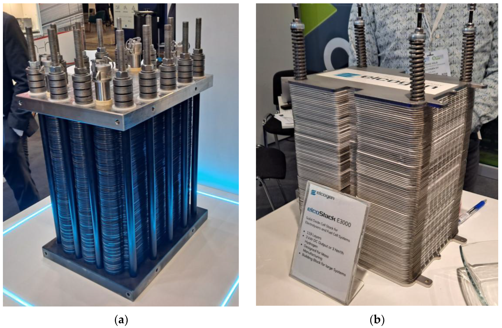
The AEM and SOEC electrolyzer stacks presented at Hyvolution 2024 and Hydrogen Technology Expo 2023 are shown in Figure 3. The first stack (Figure 3a) is built using AEM technology, while the second (Figure 3b) uses SOEC technology. The latter operates at 650 degrees Celsius and can function as both an electrolyzer and a solid-oxide fuel cell (SOFC).
The available scientific evidence and market observations clearly indicate that PEM electrolyzers are the most effective hydrogen production technology for fuel cell-based transportation and, to a lesser extent, for combustion vehicles adapted to hydrogen combustion. They are characterized by superior product quality, high efficiency, operational flexibility, and the potential for integration with renewable energy sources. Although their cost is still high, the dynamic development of technology and the scale of implementation suggest that PEM will maintain its competitive advantage in the coming years.
Currently, several types of 2 MW electrolyzers with scalable capacities are available on the European market [87]. Manufacturers’ websites detail the advantages and disadvantages of each technology [88,89,90]. However, only commercial implementation and monitored operation over several years can confirm their long-term performance. It is worth noting that many of the latest electrolyzer solutions have been developed in recent years by newly established start-ups. Investors intending to produce green water for transportation and other purposes should take this into consideration [91].
In 2025, the role of artificial intelligence in every field of technology and science cannot be ignored. Artificial intelligence supports the development of PEMFC fuel cells and PEMWE electrolyzers, enabling the creation of advanced control strategies that adapt to changing operating conditions and increase the accuracy of maintaining optimal parameters. Machine learning algorithms enable fault prediction, anomaly detection, and real-time system optimization, translating into higher efficiency and longer system life. AI enables a gradual transition from traditional automation to fully autonomous process management in PEMFCs and PEMWEs [92]. Research published by another team of scientists also shows that artificial intelligence (AI) can effectively support the development of hydrogen technologies, such as PEMFC fuel cells and PEMWE electrolyzers, primarily by improving the control strategies for these systems [93]. Machine learning algorithms enable better modeling of complex, nonlinear relationships between subsystems (gas supply, power, thermal, and water systems), which increases control accuracy and enables rapid response to disturbances. AI also supports fault prediction and diagnosis, optimizes energy consumption, and enables the creation of hybrid control systems that combine the advantages of traditional and advanced methods, representing a step toward fully autonomous hydrogen systems.
Proton exchange membrane (PEM) electrolyzers typically achieve a system efficiency of 60–70% (LHV basis) under nominal operating conditions, with stack efficiencies reaching up to 75% in optimized setups. For comparison, alkaline electrolyzers generally operate at 55–65%, while solid-oxide electrolyzers (SOEC) can exceed 80% when integrated with high-grade waste heat sources. Table 1 summarizes representative energy conversion rates for common electrolyzer technologies, based on the recent literature and manufacturer data [94].

4. Compressing, Transporting, and Refueling Hydrogen

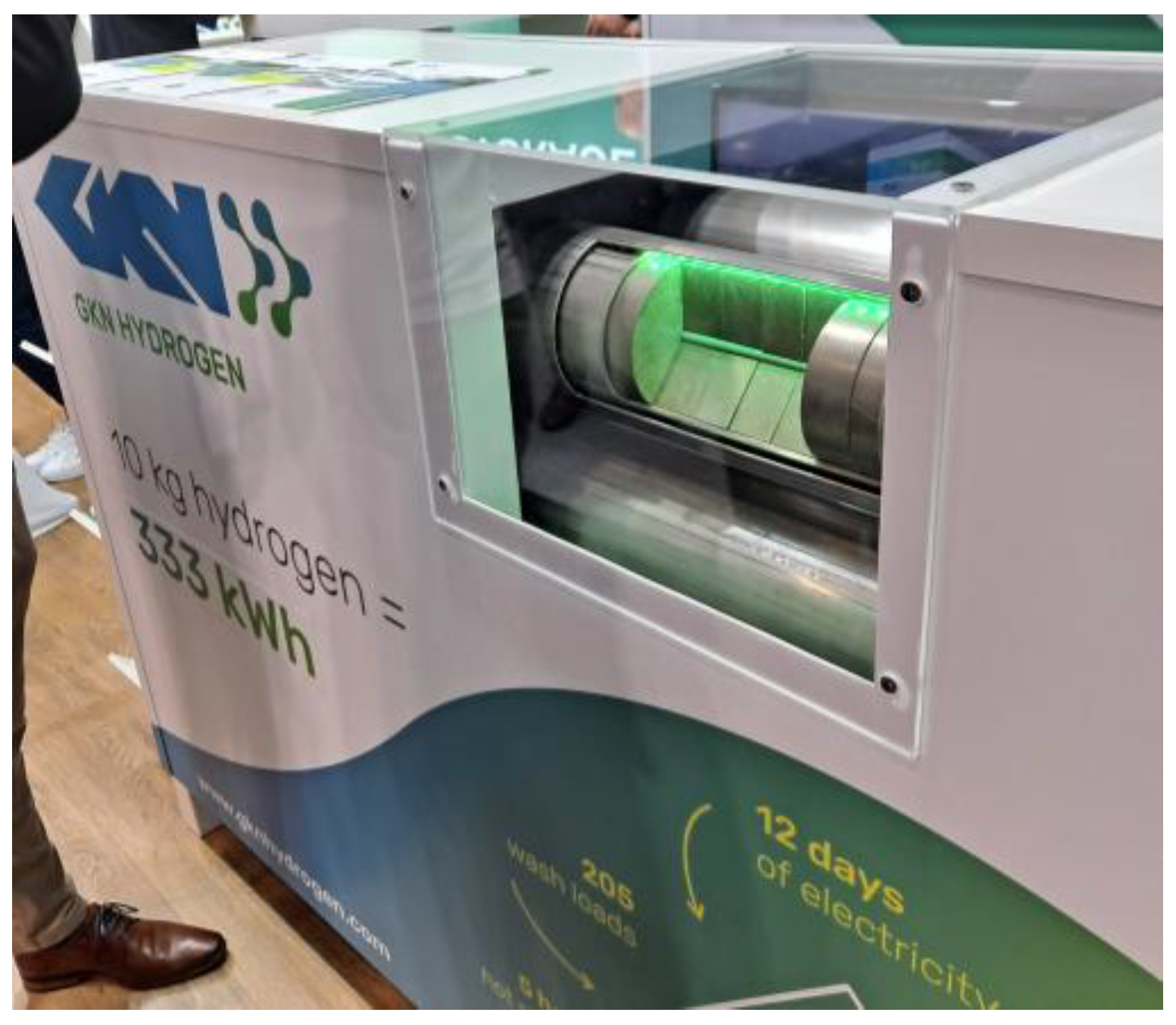
Hydrogen produced through electrolytic processes typically has a pressure of no more than 30–50 bar. Hydrogen at this pressure can only be stored in metal hydrides. An example of this type of device presented at the Hydrogen Technology Expo 2023 is shown in Figure 4. However, even after the hydrogen is released through heating, it must be compressed to the high pressures required for hydrogen vehicles.
To achieve the pressure required in hydrogen buses (350 bar) or passenger cars (700 bar), it must be efficiently compressed to high pressures. Multistage compression systems are used for this purpose, typically reciprocating compressors. Hydrogen for transportation purposes using hydrogen fuel cells requires compressors that provide oil-free compression. Compressing 1 kg of hydrogen from 30 bar to 700 bar with 65% efficiency requires approximately 3 kWh of energy [95].
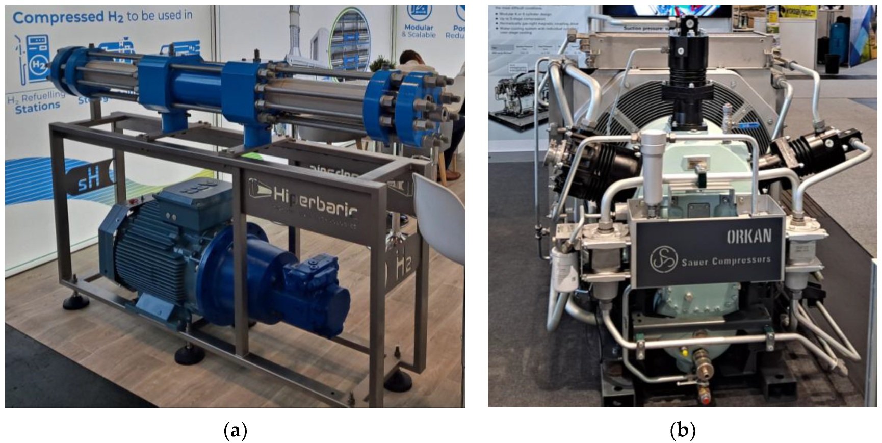
The high-pressure oil-free hydrogen compression equipment presented at the Hydrogen Technology Expo 2023 is shown in Figure 5. The device shown in Figure 5a is available in two compression pressure options: 500 bar and 1000 bar. The device shown in Figure 5b operates with six compression stages and has a nominal pressure of 350 bar and a flow rate of up to 1000 m3/h.
In the case of hydrogen vehicles, as in the case of electric vehicles, access to the refueling infrastructure is crucial. Based on the literature reviewed, it can be concluded that the development of hydrogen compression, transport, and refueling technologies for hydrogen vehicles is currently in the phase of intensive research and gradual market implementation. This state is characterized by significant progress in materials, infrastructure, and energy efficiency, but it also poses significant technological, economic, and safety challenges.
Hydrogen compression is a key step in enabling its efficient storage and transport. The most common method is compressing hydrogen to pressures of 350–700 bar, which increases its energy density and enables storage in relatively compact tanks. Typical compression systems use reciprocating, diaphragm, or screw compressors, with reciprocating compressors most commonly used in large installations (e.g., hydrogen farms) because of their scalability and efficiency at high flow rates [96]. However, the compression process is energy-intensive—at 700 bar, energy losses can amount to 10–15% of the hydrogen’s energy content. Additionally, high pressures pose a risk of material embrittlement, leaks, and potential explosions, requiring the use of advanced materials such as carbon fibers and specialized composites [97].
Three main methods are used to transport hydrogen: compressed, liquid, and chemical. Compressed hydrogen transport technology is the most advanced, particularly in the context of hydrogen vehicle refueling station infrastructure. Type III and IV tanks, used in road transport and passenger cars, enable hydrogen storage at pressures up to 700 bar. An alternative is the transport of liquid hydrogen (LH2), which requires cooling to −253 °C and maintaining high insulation, resulting in higher energy costs and evaporative losses (boil-off). In practical applications, boil-off rates for stationary storage and transport tanks typically range from 0.2% to 0.6% of stored mass per day for large-scale facilities, and up to 1% per day for smaller mobile tanks, depending on insulation quality and ambient conditions [98]. Modern designs employ multilayer vacuum insulation with low-emissivity reflective foils, minimizing conductive and radiative heat transfer. For long-distance maritime transport, boil-off gases are often recovered and used as fuel for propulsion or re-condensed using onboard re-liquefaction units. Additional strategies under development include composite cryogenic tanks with integrated getters to trap residual gases, optimized tank geometries to reduce surface-to-volume ratios, and active thermal management systems to stabilize internal temperatures during transit. These advancements are critical to improving the economic viability of LH2 supply chains by reducing hydrogen losses during storage and distribution. Despite this, LH2 is the preferred form of long-distance transport because of its higher volumetric energy density.
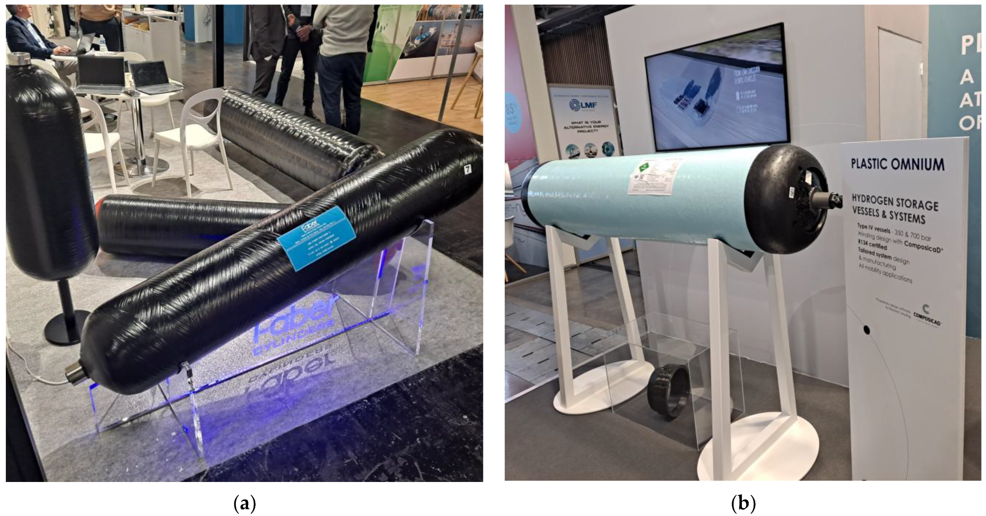
The composite high-pressure cylindrical hydrogen tanks presented at Hyvolution 2024 are shown in Figure 6. The first tank (Figure 6a) has a capacity of 134 L and weighs 157 kg, while the second tank (Figure 6b) has a capacity of 304 L and weighs 183 kg. The latter operates at a pressure of 70 MPa (700 bar). The manufacturer guarantees 11,000 tank-filling cycles. In current industry practice, high-pressure hydrogen tanks operating at above 300 bar are considered the standard solution, with 350 bar systems typically used in buses and 700 bar systems in passenger cars. Ongoing research and development in this area is focused primarily on improving operational safety, material durability, and resistance to hydrogen embrittlement, as well as ensuring long-term reliability under repeated refueling cycles. Key directions include enhancing crash resistance, integrating advanced leak detection systems, and optimizing composite structures to increase service life while maintaining low weight. Reductions in tank dimensions are generally a secondary objective, pursued only if they can be achieved without compromising safety, refueling performance, or driving range.
Hydrogen refueling stations (HRS) are crucial for the development of hydrogen mobility. Hydrogen refueling is performed under high pressure and requires precise temperature management, typically by pre-cooling the gas to −40 °C to avoid excessive temperature rise in the vehicle tank during rapid filling [99]. The refueling process must be automated, fast, and compliant with user requirements, which requires the use of advanced pressure regulation, cooling, and flow control systems. Applicable technical standards, as well as the development of numerical models, support the design of increasingly efficient and safe stations.
From an infrastructure perspective, the development of hydrogen refueling station networks is still limited, particularly outside of Asia and Western Europe. The EU has adopted regulations requiring the construction of HRS stations every 100 km along major TEN-T transport corridors and every 400 km for liquid hydrogen stations, providing a significant boost to market development. However, varying standards (350 vs. 700 bar, compressed vs. liquid hydrogen) complicate coordination between vehicle manufacturers and infrastructure operators. The uneven geographical distribution of hydrogen refueling stations in Europe results from a combination of policy priorities, market maturity, and economic incentives. Western and Northern European countries—such as Germany, the Netherlands, Denmark, and France—have incorporated hydrogen mobility into national energy transition strategies and backed these plans with substantial public co-funding, often covering up to 50–80% of capital costs for HRS deployment. These regions also benefit from higher hydrogen vehicle adoption rates, creating stronger demand signals for private investors. In contrast, many Central and Eastern European countries remain in the planning phase because of the absence of dedicated national hydrogen roadmaps or delayed implementation of EU directives, coupled with limited availability of public funding mechanisms for alternative fuels infrastructure. Economic factors, such as smaller initial market size, lower purchasing power of fleet operators, and higher perceived investment risk, further slow down private sector engagement. Additionally, existing natural gas and conventional fuel supply chains in these regions have historically received stronger policy support, delaying the diversification towards hydrogen. Overcoming these barriers will require targeted policy instruments, cross-border coordination, and early-stage risk-sharing mechanisms to stimulate market entry in less developed regions.
In the European Union, the 2024 “H2 Accelerates” program increased the previously adopted deployment targets by approximately 47%, aiming to achieve a denser station network along the TEN-T corridors and in metropolitan areas by 2030. In China, the “Hydrogen into Ten Thousand Homes” initiative has introduced technological breakthroughs in liquid hydrogen refueling stations, particularly for heavy-duty trucks, demonstrating both cryogenic storage advances and rapid fueling protocols at scale [100]. Furthermore, according to [101], the global growth rate of hydrogen stations in 2023 exceeded earlier projections by 18–22%, reflecting accelerated investment in Asia and Europe. Taken together, these updates indicate that hydrogen refueling infrastructure is developing faster than anticipated in earlier studies, underscoring the need for continuous monitoring of policy adjustments and industry commitments when evaluating the feasibility of hydrogen mobility.
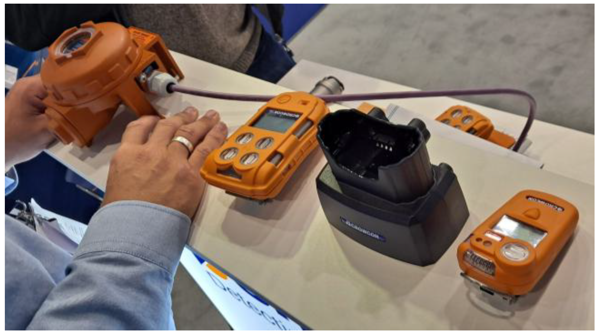
At the same time, safety plays a crucial role—both during the compression, transport, and use of hydrogen [102]. Risks include leaks, explosions, material embrittlement due to hydrogen, and hazards related to low temperatures in the case of liquid hydrogen [103]. This necessitates the use of numerous safety systems, including safety valves, leak detectors, and solutions to minimize the effects of potential failures (see Figure 7).
Currently, the hydrogen refueling infrastructure in Europe is not yet sufficient to fully support the mass deployment of hydrogen vehicles—both passenger cars and trucks. Despite dynamic development and growing interest from governments and industry, the network of hydrogen stations remains geographically limited, unevenly distributed, and often concentrated in a few countries [104]. Germany leads the way in Europe, with over 90 HRS (hydrogen refueling stations), primarily in cities and on major routes. France, the Netherlands, Denmark, and Norway are developing the infrastructure through national and EU projects. Central and Eastern Europe (including Poland) has a very limited number of stations—the infrastructure is only in the planning or pilot phase [105]. Europe has a developed infrastructure in some areas, but it is not yet dense enough to support seamless inter-country mobility. Furthermore, the European hydrogen refueling infrastructure is not integrated across countries and scalable to support large vehicle fleets (especially trucks and commercial vehicles) [106].
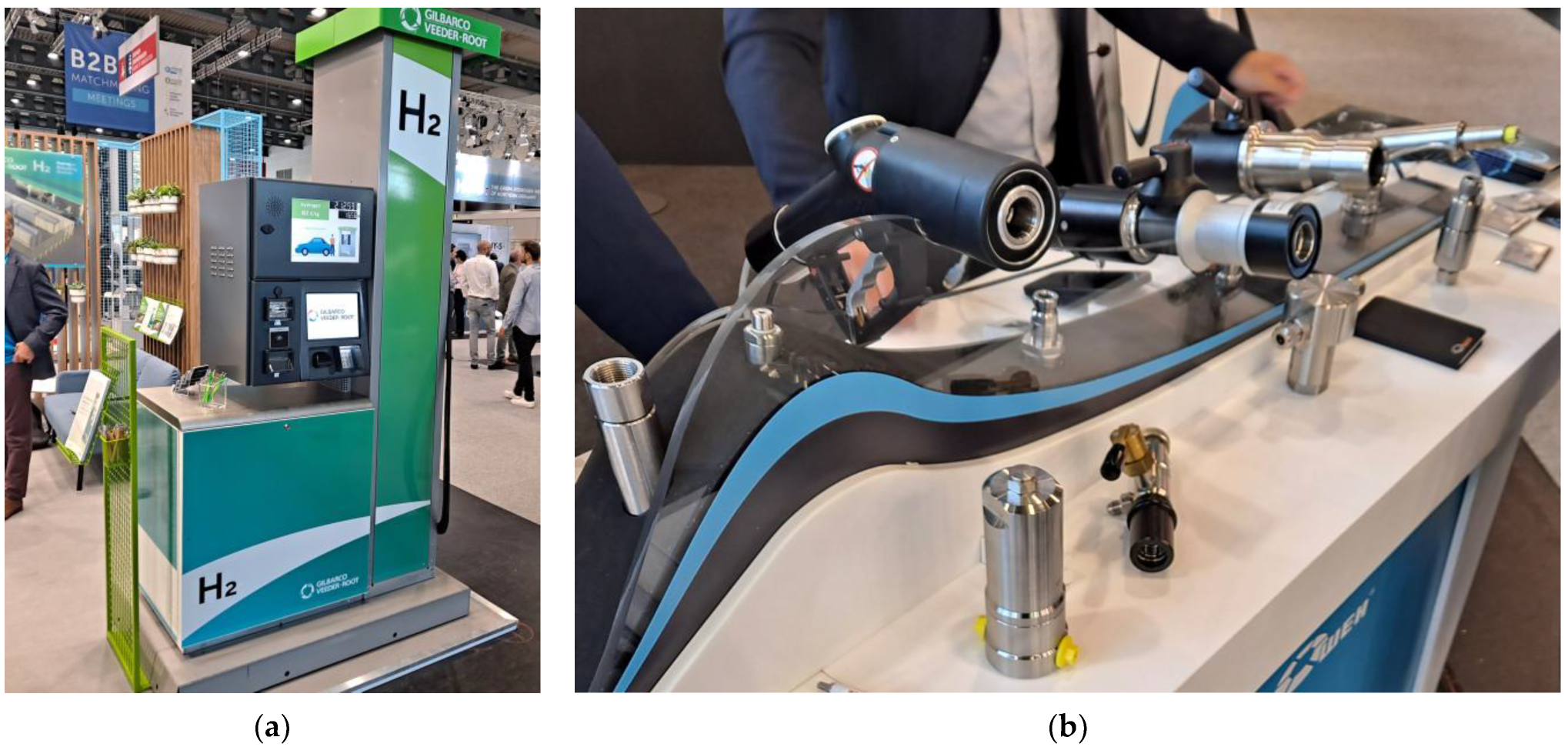
Technologies for dispensing hydrogen compressed to 350 and 700 bar are available on the market and were presented at the Hydrogen Technology Expo 2023. Figure 8a shows a hydrogen dispenser. The display shows the hydrogen price of 12.85 EUR/kg. Safe hydrogen refueling requires secure refueling nozzles on both the vehicle and the dispenser, as shown in Figure 8b).
Hydrogen storage and transportation options—including compressed gas (>350 bar), cryogenic liquid hydrogen (LH2), and chemically bound carriers such as ammonia—differ in terms of volumetric energy density, infrastructure requirements, energy efficiency, and safety considerations. Compressed hydrogen is technically mature and benefits from lower boil-off risk, but has lower volumetric density (~5.6 MJ/L at 700 bar) and requires heavy tanks. Liquid hydrogen offers higher density (~8.5 MJ/L) but incurs boil-off losses of 0.2–1%/day and requires energy-intensive liquefaction (~30% of LHV). Ammonia, with an energy density of ~12.7 MJ/L and established transport infrastructure, can serve as a hydrogen carrier via cracking, but the process adds conversion losses and requires addressing NOx emissions. The choice between these pathways depends on application scale, transport distance, and end-use technology, and it directly affects cost competitiveness in mobility and stationary markets.

5. Hydrogen as a Fuel for Hydrogen Fuel Cells and Internal Combustion Engines

Low-emission hydrogen is an excellent fuel for both hydrogen fuel cells and internal combustion engines. These are completely different technologies used to power various means of transport. The advantage of pure hydrogen in powering both FCs and ICEs lies primarily in the environmental friendliness of these solutions already available on the automotive market. Selected technologies for FCs and ICEs powered by low-emission hydrogen are presented below. Ongoing research and development in these two areas is increasingly being commercialized. Safe and homologated components and systems are part of innovative vehicles already available on the market. Growing interest in hydrogen drives, which offer numerous advantages, is increasing the scale of their production for various types of vehicles, translating into lower costs. Scientists frequently discuss the total cost of ownership (TCO) comparison between hydrogen models and traditional fossil fuel-powered models [107]. It turns out that over a longer timeframe of up to 10 years, the TCO for hydrogen and traditional vehicles is very similar. The TCO calculation methodology allows for the determination of individual costs related to the purchase and operation of individual means of transport [108].

5.1. Hydrogen as a Fuel for Hydrogen Fuel Cells

Hydrogen-powered fuel cells are electrochemical generators of electricity and heat that can be successfully used to power a variety of vehicles. These include passenger cars, buses, delivery vehicles, and trucks, as well as locomotives and vessels [109]. Each of these applications can be powered by a hydrogen fuel cell system and an electric motor. History also knows examples of hydrogen being used in space missions. In fact, we should begin this chapter with these applications. Due to their numerous advantages and the high unit production costs, hydrogen fuel cells found their first commercial applications in space technologies. Some of the first astronauts were able to drink water produced as a byproduct of fuel cell operation [110]. Heat and electricity will also be useful aboard any vehicle and spacecraft.
Hydrogen fuel cells were first used in space by NASA in the 1960s during the Gemini program as a compact source of electricity and potable water for astronauts. In subsequent missions, such as the Apollo and Space Shuttle missions, these cells played a crucial role thanks to their high efficiency and reliability in vacuum conditions. This technology remains a vital component of power systems for both manned and unmanned missions, laying the foundation for future flights to the Moon and Mars. The increasingly widespread use of fuel cells in space and ongoing research to improve these technologies (many types of fuel cells exist) have opened up the possibility of their use in vehicle propulsion. The first prototypes of such vehicles appeared over 25 years ago. Many global automotive companies now have hydrogen fuel cell vehicles on the market. Let us take a closer look at these technologies.
In the face of the global energy transformation, fuel cell technology is gaining importance as a key element of sustainable transport. Proton exchange membrane fuel cells (PEMFCs) play a particularly important role, characterized by high efficiency (up to 60%), rapid start-up time, and zero emissions during operation [111].
One of the key operational challenges for FCVs is efficiency at low temperatures. The development of waste heat recovery systems from PEMFCs addresses this issue. Studies show that optimized heat exchangers enable effective cabin heating even at temperatures as low as −30 °C, while reducing auxiliary energy consumption by up to 57.6%.
In parallel, methods using artificial intelligence to monitor and predict fuel cell failures are being intensively developed. Models based on neural networks, support vector machines (SVMs), and genetic algorithms allow for the prediction of voltage drops and operating errors with high precision, supporting system reliability [112]. From a practical perspective, FCVs offer advantages over traditional electric vehicles: longer range, shorter refueling times, and better acceleration. For example, hydrogen buses accelerate from 0 to 50 km/h in just 8 s and climb steeper gradients than their combustion-powered counterparts [113].
Using surplus renewable energy to produce hydrogen (so-called green hydrogen) is also becoming increasingly important, allowing for energy storage and subsequent use in fuel cell vehicles. Research shows that using excess hydrogen from electrolysis as a power source in mobile or backup systems (e.g., in service vehicles) opens up new business opportunities and supports low-emission infrastructure [114].
However, the sustainability of FCEVs depends on the method of hydrogen production. Lifecycle analyses (LCAs) indicate that only hydrogen produced from renewable energy significantly reduces greenhouse gas emissions [115,116]. Production based on fossil fuels can generate higher emissions than combustion vehicles.
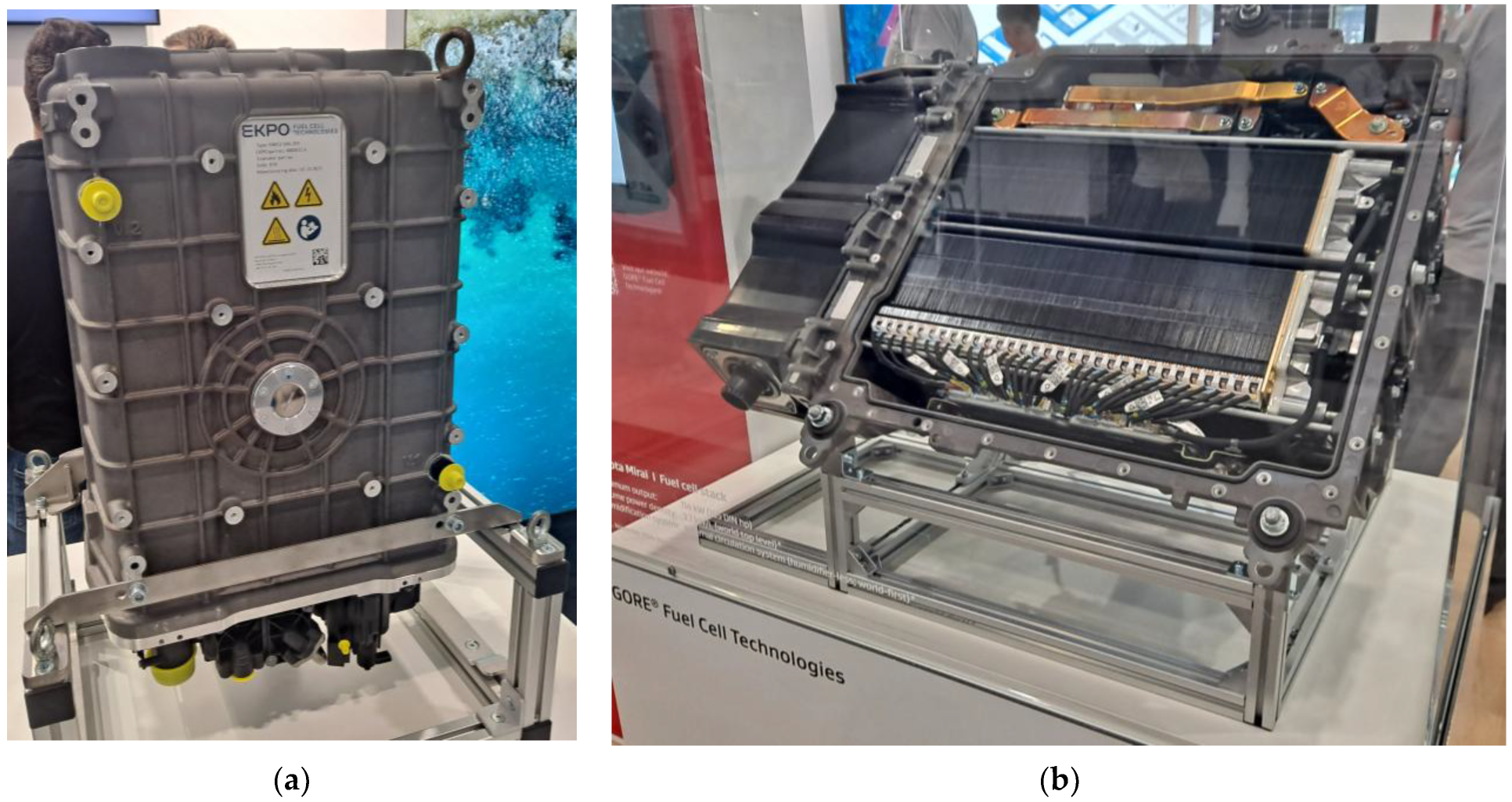
Fuel cell stacks for automotive applications are currently typically based on PEM fuel cells. Figure 9 shows two complete commercial hydrogen fuel cell systems presented at the Hydrogen Technology EXPO 2023 trade fair. The first (Figure 9a) contains 359 PEMFC cells and generates over 100 kW of electrical power. The manufacturer also offers a twin system based on two identical fuel cell stacks. These cells use metallic bipolar plates and a liquid cooling system. The second figure (Figure 9b) is the power source for the most popular commercial hydrogen vehicle, the Toyota Mirai I. Generating a nominal power of 114 kW, the fuel cell system has a volumetric power density of 3.1 kW/liter.
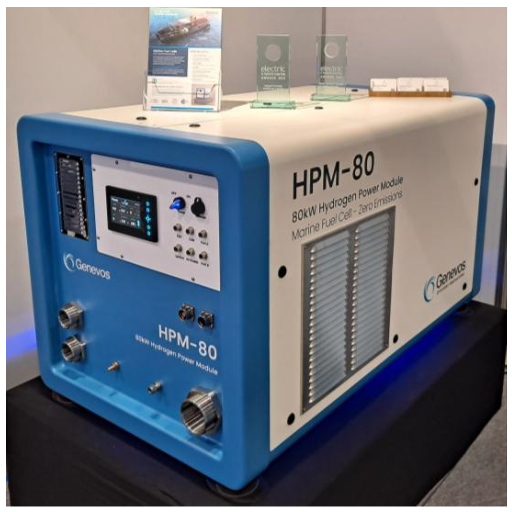
A fuel cell system designed for marine transport should be resistant to the corrosive effects of air and seawater [117]. An 80 kW marine-grade stack presented at the Hydrogen Technology Expo 2023 is shown in Figure 10.
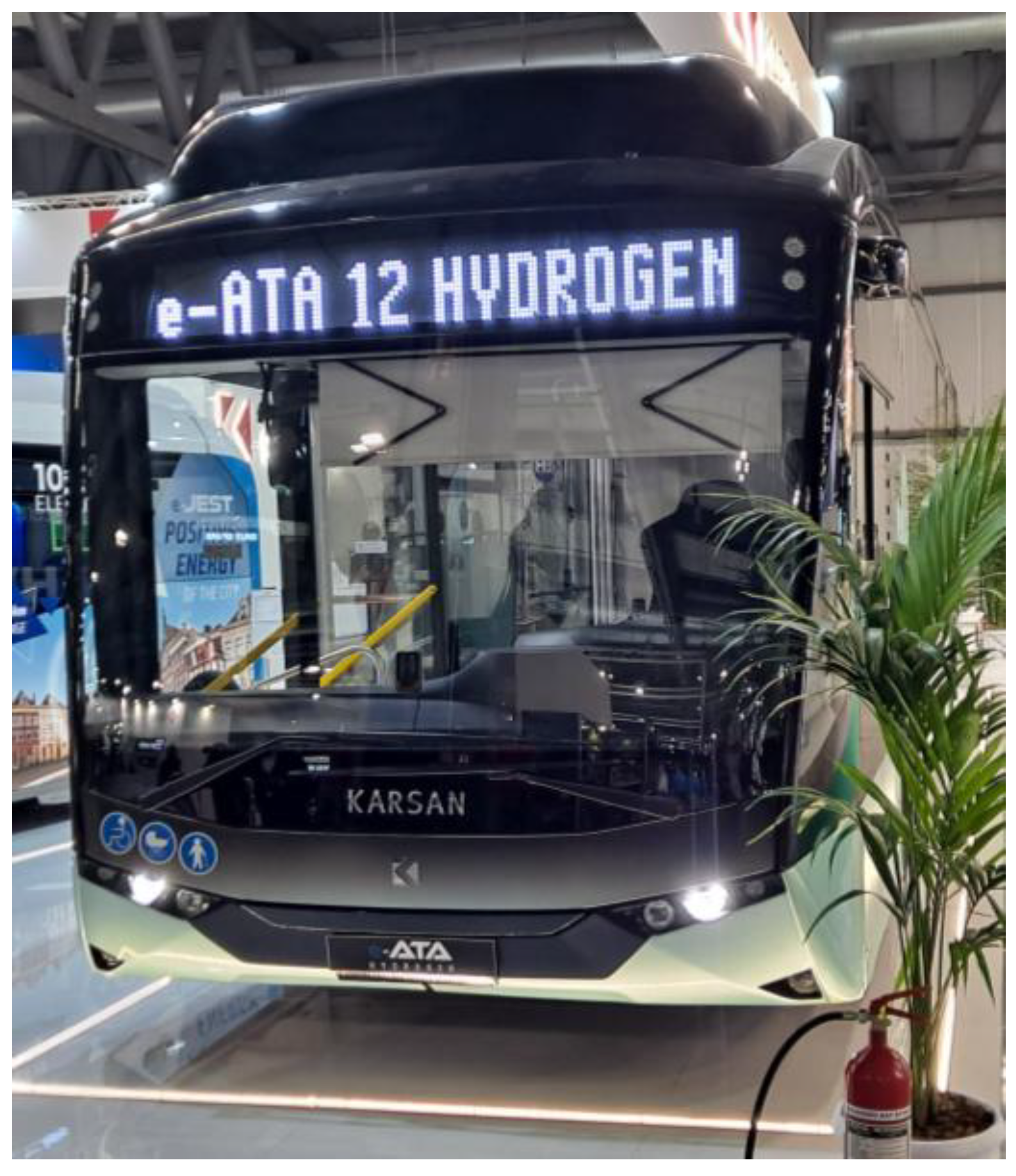
The hydrogen city bus with a range of 500 km presented at the Next Mobility 2024 trade fair in Milan is shown in Figure 11. The Karsan e-ATA 12 Hydrogen is a 12 m low-floor hydrogen fuel cell bus designed for public transportation. It features a 70 kW fuel cell, a 30 kWh LTO battery, and a 1560 L hydrogen tank, offering a range of over 500 km. The bus can carry over 95 passengers and can be refueled in under 7 min. The Turkish manufacturer’s fuel cell bus is powered by Ballard’s FCmove®-HD 70kW system [118].

5.2. Selected Problems in the Implementation of Hydrogen Fuel Cell Vehicles

In real-world applications, particularly in urban bus fleets, PEM fuel cells are subjected to highly dynamic duty cycles characterized by frequent starts, stops, and rapid load fluctuations. These operational patterns impose mechanical and chemical stresses on the membrane–electrode assembly (MEA), including increased membrane hydration/dehydration cycling, accelerated catalyst layer degradation, and higher rates of platinum dissolution and carbon support corrosion. Field studies have shown that durability under such dynamic conditions can be reduced by 30–50% compared with steady-state laboratory testing, with mean time to stack refurbishment dropping from over 20,000 h to as low as 12,000–14,000 h [119]. Therefore, accurate lifetime prediction models and control strategies must incorporate dynamic load profiles representative of target applications to ensure realistic performance expectations and maintenance planning.
An important direction for future research is the integration of advanced control strategies with long-term state-of-health (SOH) estimation and degradation prediction under real-world dynamic operating conditions [120]. Recent studies have demonstrated that time-varying dynamic degradation models, combined with data-driven approaches such as improved Informer architectures, can accurately forecast voltage decay trends and periodic recovery phenomena in PEMFC stacks over thousands of operating hours, achieving root mean square errors below 1.05 V and mean absolute percentage errors under 0.5%. The incorporation of such prognostic frameworks—particularly in cloud-based monitoring systems—would enable continuous SOH assessment for each operational period, improving maintenance planning and informing adaptive control strategies. Coupling real-time control with accurate long-term prognostics could bridge the gap between laboratory performance metrics and actual field durability, especially for demanding applications such as urban bus fleets with frequent load transients.
In real-world vehicular applications, rapid acceleration and deceleration can cause transient shifts in water distribution within the PEMFC stack, leading to localized membrane drying or flooding. Such uneven hydration not only increases the risk of hot spot formation and accelerated membrane degradation but can also extend start-up times because of the need for rebalancing internal water content. Supplemental water management strategies—such as optimized purge control, controlled humidification ramping, and differential pressure regulation—have been shown to mitigate these effects, thereby improving both start-up performance and long-term stack reliability [121]. These findings underscore that water management is intrinsically linked to the fast-start capability and operational flexibility of PEMFC systems.
Proton exchange membrane fuel cells (PEMFCs) face significant operational challenges during cold starts, particularly below −20 °C, where water in the membrane and gas diffusion layers can freeze, blocking reactant flow paths and reducing ionic conductivity. At −30 °C, start-up without preheating can lead to rapid voltage drop and potential membrane damage due to ice expansion. Effective cold start strategies include controlled heating via external resistive elements, catalytic hydrogen combustion, optimized purge cycles to remove liquid water before shutdown, and advanced thermal management using liquid-cooling circuits with antifreeze mixtures. The literature provides detailed modeling of heat distribution and phase change during cold starts, demonstrating that a combination of preheating and dynamic load control can enable reliable start-up within 60–120 s even at −30 °C [122]. Such strategies are critical for ensuring year-round operation in cold climates and for meeting automotive reliability standards.
Predictive techniques are becoming increasingly popular, enabling predictions of degradation and remaining service life of hydrogen fuel cells, allowing for optimized maintenance schedules and reduced operating costs. Using models based on operational data and machine learning methods, anomalies can be detected early, and control strategies can be adapted to extend system durability. It should be noted that some predictive models for PEMFC durability are trained on limited datasets, for example, operational data from a single vehicle type, which may not capture the full range of load profiles, environmental conditions, and usage patterns encountered in commercial fleets. As a result, prediction errors in certain scenarios can reach 20–30%, potentially overestimating the model’s generalization capability. Recent studies on fuel cell life prediction that incorporate the recovery phenomenon of reversible voltage loss demonstrate that integrating such effects into modeling can significantly improve prediction accuracy and better reflect the actual degradation pathways observed in field applications [123]. From a commercial standpoint, more accurate life prediction directly influences infrastructure planning, investment prioritization, and maintenance scheduling, thereby reducing operational risks and improving the economic viability of hydrogen-powered transport systems.

5.3. Hydrogen as a Fuel for Internal Combustion Engines

Clean, low-emission hydrogen is also an excellent fuel for internal combustion engines. Due to the power they generate, these can power a wide range of vehicles. Although work on hydrogen combustion in combustion engines began a long time ago, vehicles using this technology are only now appearing on the market. Do they compete with hydrogen fuel cells in the automotive industry? Is hydrogen combustion in an internal combustion engine more economical and ecological than its chemical conversion in fuel cells? Finally, which technology is currently more widely used, and which will dominate the future of transportation? These questions will be answered in this section.
Combustion of hydrogen in internal combustion engines is an interesting and increasingly promising alternative to traditional fossil fuels in automotive applications. One of the key advantages of this technology is its lack of carbon dioxide emissions—hydrogen contains no carbon atoms, and its combustion product is only water vapor [124]. This allows hydrogen engines to significantly contribute to the decarbonization of transport and improve air quality. Another significant advantage is the ability to use hydrogen in conventional piston engine designs, allowing for the adaptation of existing production and service infrastructure without the need to implement entirely new technologies, as is the case with fuel cells or battery drives [125].
Studies have shown that using hydrogen as an additive to conventional fuels can improve engine thermal efficiency by several percentage points and significantly reduce emissions of harmful compounds such as carbon monoxide and hydrocarbons [126]. The ability to operate on very lean fuel–air mixtures, resulting from hydrogen’s wide flammability range, further reduces NOx emissions and increases engine efficiency [127]. Additionally, hydrogen has a very low ignition energy and high flame propagation speed, which translates into improved combustion stability—especially in low ambient temperatures or at low loads.
Hydrogen combustion technology has potential applications, particularly in heavy-duty and specialized transport, where electric drives prove insufficient because of limited range, long battery charging times, and high energy requirements [128,129]. Unlike fuel cells, hydrogen engines are structurally simpler, less sensitive to fuel purity, and do not require the use of expensive catalytic converters or materials such as platinum. This makes them a cheaper and more quickly implemented technology in many automotive applications.
It should be noted, however, that despite its many advantages, hydrogen combustion is not without its challenges [130]. High combustion temperatures can lead to the formation of nitrogen oxides (NOx), but these can be reduced by operating on lean mixtures or using water injection, which effectively lowers cylinder temperatures [128]. Experimental studies indicate that operating hydrogen internal combustion engines on lean fuel–air mixtures (excess air ratios λ = 2.0–2.5) can reduce NOx emissions by approximately 50–70% compared with stoichiometric operation, while maintaining acceptable engine efficiency [119]. Additional application of direct water injection—at water-to-fuel mass ratios of 0.4–0.6—has been shown to further lower NOx levels by 40–60% relative to lean-burn alone, primarily through peak in-cylinder temperature reduction [131]. For example, tests conducted on a turbocharged 2.0 L hydrogen ICE demonstrated a drop in NOx emissions from ~1.2 g/kWh (lean-burn) to ~0.5 g/kWh when water injection was applied, with only a marginal impact (<2%) on brake thermal efficiency. These results confirm that combining lean-burn combustion with optimized water injection strategies offers a robust pathway for achieving low-NOx hydrogen engine operation without excessive efficiency penalties. Furthermore, hydrogen’s low energy density and the challenges of storing it at high pressure require appropriate engineering solutions [132].
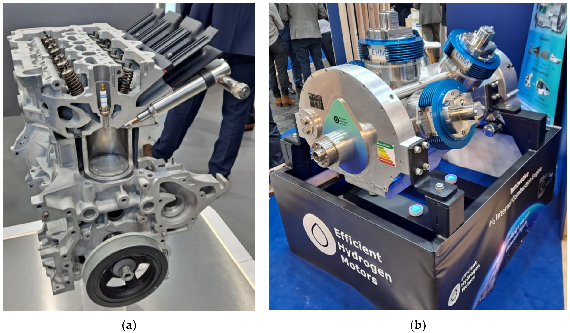
At Hyvolution 2024, powertrains based on hydrogen-burning internal combustion piston engines were presented, as shown in Figure 12. Figure 12a shows a four-cylinder 1.6 L powertrain developed by Aramco in collaboration with Hyundai and Bosch. The turbocharged hydrogen powertrain has a compression ratio of 9.5 and generates a maximum power of 132 kW at an engine speed of 5500 rpm. Maximum torque is 265 Nm, constant between 1500 and 4500 rpm. This performance allows for use in most passenger cars and small commercial vehicles. Hydrogen internal combustion engines can be gasoline or diesel engines adapted to burn hydrogen, or individually developed engines specifically designed from the outset to run on hydrogen, as shown in Figure 12b. It should be noted that this is a project developed since 2022 by a French start-up.
Combustion of hydrogen in piston engines offers a real opportunity to reduce emissions in the transport sector while leveraging existing infrastructure and the expertise of the automotive industry. It could be an important transitional step towards the full decarbonization of the transport sector [133].

5.4. Hydrogen Fuel Cell Vehicles and Hydrogen Combustion Engine Vehicles—Bottlenecks in Commercialization

A critical bottleneck in the industrialization of proton exchange membrane fuel cells (PEMFCs) is their reliance on platinum group metals (PGMs), primarily platinum (Pt) and iridium (Ir), as electrocatalysts [134]. These materials provide the high activity and durability required for hydrogen oxidation and oxygen reduction reactions, but their limited global availability and high cost significantly affect the overall system price. Current PEMFC stacks typically require 0.1–0.3 g Pt/kW, and further scale-up of production to heavy-duty transport sectors would impose a substantial demand on the global Pt supply. Recent research, therefore, focuses on reducing catalyst loading, improving catalyst recycling, and developing non-precious alternatives [135]. Nevertheless, the cost and resource constraints associated with PGMs remain one of the most significant industrialization challenges for FC technology [136].
In addition to catalyst-related costs, membrane durability constitutes another critical bottleneck for proton exchange membrane fuel cells. The most widely used membranes, such as Nafion® and perfluorosulfonic acid (PFSA) types, have been extensively studied, including recent investigations into Dongyue series PFSA membranes, which offer improved proton conductivity and chemical stability [137]. However, long-term degradation under dynamic operating conditions—such as radical attack, dehydration/rehydration cycles, and mechanical stress—remains a key barrier to extending stack lifetime [138]. Alternative approaches include the development of sulfonated poly(ether ether ketone) (sPEEK) membranes with varying degrees of sulfonation, which provide promising durability and lower cost potential [139,140]. Nevertheless, their performance still depends strongly on optimizing the balance between proton conductivity, mechanical strength, and chemical stability [141]. These membrane-related issues, together with catalyst cost, highlight the complex material challenges that must be addressed to achieve sustainable large-scale commercialization of PEMFC systems.
Although hydrogen internal combustion engines (H2-ICEs) eliminate CO2 emissions, they present significant challenges with respect to nitrogen oxide (NOx) formation because of high in-cylinder flame temperatures. Lean-burn operation and water injection can reduce NOx, but recent studies, including Toyota’s investigations into direct-injection hydrogen engines, have demonstrated abnormal combustion phenomena such as pre-ignition and backfiring under certain operating conditions [142]. These issues complicate reliable engine calibration and emission compliance [143]. Advanced control strategies, exhaust after-treatment, and optimized combustion chamber designs are therefore essential to mitigate NOx while ensuring stable performance [144]. This highlights that although ICE adaptation is technologically straightforward, emission control remains a crucial industrialization barrier.
Beyond efficiency and compatibility considerations, the lifecycle cost of ownership (LCOH) represents a decisive factor in assessing the competitiveness of FC and H2-ICE technologies. Recent techno-economic analyses show that the LCOH of FC vehicles is dominated by the cost of hydrogen (currently 4–8 EUR/kg for green H2) and the capital cost of stacks, which require periodic refurbishment or replacement [145]. In contrast, H2-ICE vehicles benefit from lower upfront costs because of the use of conventional engine architectures, but their lower efficiency results in higher hydrogen consumption per kilometer. Sensitivity analyses indicate that, under projected hydrogen costs of 2–3 EUR/kg by 2035, FC vehicles achieve lower per-kilometer fuel costs, whereas H2-ICEs may retain an advantage in early deployment phases because of lower capital costs and faster scalability. Thus, the two pathways exhibit complementary cost profiles depending on the time horizon and market maturity.
An in-depth analysis of the bottlenecks in the commercialization of these two hydrogen technologies leads to one final conclusion: while fuel cells offer superior efficiency and long-term cost advantages, but face material resource constraints, hydrogen internal combustion engines provide a more immediate pathway to commercialization, though they require continued progress in emission control and combustion stability.

6. Conclusions

This article presents a comprehensive overview of hydrogen technologies in the context of their application in road transport. The author analyzes both the technical aspects of fuel cells and hydrogen combustion engines, as well as issues related to hydrogen production, storage, and distribution. Particular attention is paid to the importance of hydrogen’s source, highlighting the key role of green hydrogen in decarbonizing transport. Barriers to its development are also highlighted, including limited infrastructure, high costs, and a lack of uniform regulations. The author concludes that hydrogen has the potential to become a strategic fuel of the future if certain technological, economic, and political conditions are met.
Based on this review of the state of technology and science, the following conclusions can be drawn:
1. Hydrogen represents a viable alternative to fossil fuels in transport, particularly in the heavy-duty and long-distance sectors.
2. Fuel cells offer higher energy efficiency but are more expensive and technologically complex than hydrogen combustion engines.
3. Combustion of hydrogen in modified piston engines can accelerate the implementation of hydrogen technology by leveraging existing infrastructure.
4. A key factor determining the environmental friendliness of hydrogen is its origin—only green hydrogen produced from renewable energy sources truly reduces emissions.
5. Storage and transportation of hydrogen remain a significant technical and cost challenge.
6. The development of hydrogen refueling infrastructure is uneven and requires intensification, particularly in developing countries.
7. The lack of uniform standards and regulations for hydrogen hinders its widespread commercialization.
8. Hydrogen can play an important role as an energy carrier, supporting grid balancing and integration with renewable sources.
9. Close cooperation between the energy sector, the automotive industry, and governments is needed to effectively implement hydrogen technologies.
10. Strategic policy, financial support, and a long-term vision are essential for hydrogen to become the foundation of the low-emission transportation of the future.
11. Hydrogen applications in transportation require high hydrogen purity, as even trace amounts of CO or sulfur can significantly shorten the life of PEMFC catalysts. This should be considered in infrastructure design and production standards.
12. The choice between compressed hydrogen, liquid hydrogen, and chemical carriers (e.g., ammonia) should be made based on an analysis of the total cost of ownership (TCO), energy density, and logistical requirements for a given market segment.
13. Advanced forecasting models can significantly improve the accuracy of fuel cell and electrolyzer lifecycle predictions for hydrogen production, which has direct commercial implications for investment and maintenance planning.
Practical cooperation between the energy sector and the automotive industry can take several forms. One proven model is the joint development of hydrogen refueling infrastructure through public–private partnerships, where energy companies supply green hydrogen and operate stations, while vehicle manufacturers commit to fleet deployment (e.g., the H2 Mobility Germany initiative). Another approach involves integrating renewable hydrogen production with captive fleet operation, as demonstrated by the “HyDeploy” and “H2BusEurope” projects, in which utility providers and bus manufacturers collaborated to optimize hydrogen supply chains for urban public transport. Industrial symbiosis schemes are also promising, where excess renewable electricity from utility-scale wind or solar farms is used for on-site hydrogen production, with guaranteed offtake by logistics or public transport operators. Such cooperative pathways combine demand assurance with infrastructure investment efficiency, thereby reducing financial risk and accelerating market adoption.

Funding

This research received no external funding.

Data Availability Statement

The original contributions presented in this study are included in the article; further inquiries can be directed to the author.

Conflicts of Interest

The author declares no conflicts of interest.

Abbreviations

The following abbreviations are used in this manuscript:
AEMAnion Exchange Membrane
ATAAir Transport Association
CCSCarbon Capture and Storage
CFDComputational Fluid Dynamics
CO2Carbon Dioxide
EMCElectromagnetic Compatibility
EMSEnergy Management System
ENTSOEuropean Network of Transmission System Operators
ESSEnergy Storage System
EUEuropean Union
EXPOInternational Exposition
HDHeavy Duty
HRSHydrogen Refueling Station
HTGRHigh-Temperature Gas-cooled Reactor
HTRHigh-Temperature Reactor
IECInternational Electrotechnical Commission
IETInstitution of Engineering and Technology
IPCCIntergovernmental Panel on Climate Change
IRENAInternational Renewable Energy Agency
ISOInternational Organization for Standardization
LHVLower Heating Value
LTOLithium Titanate (Battery)
NASANational Aeronautics and Space Administration
NEDCNew European Driving Cycle
NRELNational Renewable Energy Laboratory
PEMProton Exchange Membrane
PEMFCProton Exchange Membrane Fuel Cell
PEMWEProton Exchange Membrane Water Electrolyzer
PMParticulate Matter
PVPhotovoltaic
SOECSolid-Oxide Electrolysis Cell
SOFCSolid-Oxide Fuel Cell
TCOTotal Cost of Ownership
TENTrans-European Networks
WLTPWorldwide Harmonized Light Vehicles Test Procedure

References

  1. Sharma, V.K.; Monteleone, G.; Braccio, G.; Anyanwu, C.N.; Aneke, N.N. A Comprehensive Review of Green Energy Technologies: Towards Sustainable Clean Energy Transition and Global Net-Zero Carbon Emissions. Processes 2025, 13, 69. [Google Scholar] [CrossRef]
  2. Kotowicz, J.; Baszczeńska, O.; Niesporek, K. Cost of Green Hydrogen. Energies 2024, 17, 4651. [Google Scholar] [CrossRef]
  3. Pivetta, D.; Dall’Armi, C.; Taccani, R. Multi-Objective Optimization of a Hydrogen Hub for the Decarbonization of a Port Industrial Area. J. Mar. Sci. Eng. 2022, 10, 231. [Google Scholar] [CrossRef]
  4. Ustolin, F.; Campari, A.; Taccani, R. An Extensive Review of Liquid Hydrogen in Transportation with Focus on the Maritime Sector. J. Mar. Sci. Eng. 2022, 10, 1222. [Google Scholar] [CrossRef]
  5. Algburi, S.; Munther, H.; Fakhruldeen, H.F.; Sapaev, I.B.; Al-Dulaimi, O.; Al Seedi, K.F.K.; Khalaf, D.H.; Jabbar, F.I.; Hassan, Q.; Khudhair, A.; et al. Green Hydrogen Role in Sustainable Energy Transformations: A Review. Results Eng. 2025, 19, 105109. [Google Scholar] [CrossRef]
  6. Gómez, J.; Castro, R. Green Hydrogen Energy Systems: A Review on Their Contribution to a Renewable Energy System. Energies 2024, 17, 3110. [Google Scholar] [CrossRef]
  7. Dai, S.; Shen, P.; Deng, W.; Yu, Q. Hydrogen Energy in Electrical Power Systems: A Review and Future Outlook. Electronics 2024, 13, 3370. [Google Scholar] [CrossRef]
  8. Lu, Z.; Li, Y.; Zhuo, G.; Xu, C. Configuration Optimization of Hydrogen-Based Multi-Microgrid Systems under Electricity Market Trading and Different Hydrogen Production Strategies. Sustainability 2023, 15, 6753. [Google Scholar] [CrossRef]
  9. Olabi, A.G.; Sayed, E.T. Developments in Hydrogen Fuel Cells. Energies 2023, 16, 2431. [Google Scholar] [CrossRef]
  10. Cărăușan, H.; Varga, B.O.; Moldovanu, D.; Prunean, G.; Oargă, I.-T. Energy Efficiency Analysis of a Fuel Cell Bus Model Using Real Scenarios Generated by Data Collection. Sustainability 2024, 16, 1863. [Google Scholar] [CrossRef]
  11. Kim, M.-S.; Jeon, H.-K.; Lee, K.-W.; Ryu, J.-H.; Choi, S.-W. Analysis of Hydrogen Filling of 175 Liter Tank for Large-Sized Hydrogen Vehicle. Appl. Sci. 2022, 12, 4856. [Google Scholar] [CrossRef]
  12. Gul, W.; Xia, Y.E.; Gérard, P.; Ha, S.K. Characterization of Polymeric Composites for Hydrogen Tank. Polymers 2023, 15, 3716. [Google Scholar] [CrossRef]
  13. Chen, Z.; Wang, H. Total Cost of Ownership Analysis of Fuel Cell Electric Bus with Different Hydrogen Supply Alternatives. Sustainability 2024, 16, 259. [Google Scholar] [CrossRef]
  14. SAE J2572; Recommended Practice for Measuring Fuel Consumption and Range of Fuel Cell and Hybrid Fuel Cell Vehicles Fueled by Compressed Gaseous Hydrogen. SAE International: Warrendale, Pennsylvania, PA, USA, 2024.
  15. Borghetti, F.; Longo, M.; Bonera, M.; Libretti, M.; Somaschini, C.; Martinelli, V.; Medeghini, M.; Mazzoncini, R. Battery Electric Buses or Fuel Cell Electric Buses? A Decarbonization Case Study in the City of Brescia, Italy. Infrastructures 2023, 8, 178. [Google Scholar] [CrossRef]
  16. Bae, S.; Lee, E.; Han, J. Multi-Period Planning of Hydrogen Supply Network for Refuelling Hydrogen Fuel Cell Vehicles in Urban Areas. Sustainability 2020, 12, 4114. [Google Scholar] [CrossRef]
  17. Wu, Q.; Dong, Z.; Zhang, X.; Zhang, C.; Iqbal, A.; Chen, J. Towards More Efficient PEM Fuel Cells Through Advanced Thermal Management: From Mechanisms to Applications. Sustainability 2025, 17, 943. [Google Scholar] [CrossRef]
  18. Padovan, C.; Fagundes, J.A.G.; D’Agosto, M.d.A.; Angelo, A.C.M.; Carneiro, P.J.P. Impact of Fuel Production Technologies on Energy Consumption and GHG Emissions from Diesel and Electric–Hydrogen Hybrid Buses in Rio de Janeiro, Brazil. Sustainability 2023, 15, 7400. [Google Scholar] [CrossRef]
  19. Muñoz Díaz, M.T.; Chávez Oróstica, H.; Guajardo, J. Economic Analysis: Green Hydrogen Production Systems. Processes 2023, 11, 1390. [Google Scholar] [CrossRef]
  20. Hidouri, D.; Ben Omrane, I.; Khalil, K.; Cherif, A. Energy Management of a 1 MW Photovoltaic Power-to-Electricity and Power-to-Gas for Green Hydrogen Storage Station. World Electr. Veh. J. 2025, 16, 227. [Google Scholar] [CrossRef]
  21. Ciuła, J.; Generowicz, A.; Gronba-Chyła, A.; Wiewiórska, I.; Kwaśnicki, P.; Cygnar, M. Analysis of the Efficiency of Landfill Gas Treatment for Power Generation in a Cogeneration System in Terms of the European Green Deal. Sustainability 2024, 16, 1479. [Google Scholar] [CrossRef]
  22. Jeje, S.O.; Marazani, T.; Obiko, J.; Shongwe, M.B. Advancing the hydrogen production economy: A comprehensive review of technologies, sustainability, and future prospects. Int. J. Hydrogen Energy 2024, 49, 642–661. [Google Scholar] [CrossRef]
  23. Brandt, J.; Iversen, T.; Eckert, C.; Peterssen, F.; Bensmann, B.; Bensmann, A.; Beer, M.; Weyer, H.; Hanke-Rauschenbach, R. Cost and competitiveness of green hydrogen and the effects of the European Union regulatory framework. Nat. Energy 2024, 9, 703–713. [Google Scholar] [CrossRef]
  24. Pan, X.; Zhou, H.; Baimbetov, D.; Syrlybekkyzy, S.; Akhmetov, B.B.; Abbas, Q. Development Status and Future Prospects of Hydrogen Energy Technology: Production, Storage, and Cost Analysis. Adv. Energy Sustain. Res. 2025, 2400451. [Google Scholar] [CrossRef]
  25. Mekuye, B.; Mebratie, G.; Abera, B.; Yibelital, A.; Lake, A.; Tolesa, A. Energy: An Overview of Type, Form, Storage, Advantages, Efficiency, and Their Impact. Highlights Sci. Eng. Technol. CEAM 2025, 116, 237–245. [Google Scholar] [CrossRef]
  26. Sebbagh, T.; Şahin, M.E.; Beldjaatit, C. Green hydrogen revolution for a sustainable energy future. Clean Technol. Environ. Policy 2024, 26, 4017–4040. [Google Scholar] [CrossRef]
  27. Akpasi, S.O.; Anekwe, I.M.S.; Tetteh, E.; Amune, U.; Mustapha, S.I.; Elshafie, A.E. Hydrogen as a Clean Energy Carrier: Advancements, Challenges, and its Role in a Sustainable Energy Future. Clean Energy 2025, 9, 52–88. [Google Scholar] [CrossRef]
  28. Münster, M.; Bramstoft, R.; Kountouris, I.; Langer, L.; Keles, D.; Schlautmann, R.; Mörs, F.; Saccani, C.; Guzzini, A.; Pellegrini, M.; et al. Perspectives on green hydrogen in Europe—During an energy crisis and towards future climate neutrality. Oxf. Open Energy 2024, 3, oiae001. [Google Scholar] [CrossRef]
  29. Lebepe, M.C.; Oviroh, P.O.; Jen, T.C. Techno-economic optimisation modelling of a solar-powered hydrogen production system for green hydrogen generation. Sustain. Energy Res. 2025, 12, 11. [Google Scholar] [CrossRef]
  30. Fan, Z. The Role of Hydrogen in Achieving Sustainable Energy Systems: Challenges and Opportunities. Highlights Sci. Eng. Technol. CEAM 2024, 116, 237–245. [Google Scholar] [CrossRef]
  31. Perissi, I.; Jones, A. Investigating European Union Decarbonization Strategies: Evaluating the Pathway to Carbon Neutrality by 2050. Sustainability 2022, 14, 4728. [Google Scholar] [CrossRef]
  32. Muhsen, H.; Hamida, F.; Tarawneh, R. The Potential of Green Hydrogen and Power-to-X to Decarbonize the Fertilizer Industry in Jordan. Agriculture 2025, 15, 608. [Google Scholar] [CrossRef]
  33. Blažek, J.; Toullis, D.; Straka, P.; Staš, M.; Šimáček, P. Influence of Pressure on Product Composition and Hydrogen Consumption in Hydrotreating of Gas Oil and Rapeseed Oil Blends over a NiMo Catalyst. Catalysts 2021, 11, 1093. [Google Scholar] [CrossRef]
  34. Tuluhong, A.; Chang, Q.; Xie, L.; Xu, Z.; Song, T. Current Status of Green Hydrogen Production Technology: A Review. Sustainability 2024, 16, 9070. [Google Scholar] [CrossRef]
  35. Pinchao, P.; Torres, A.; Yánez, M.; Reina, S.; Cando, E. Analysis for the Implementation of Surplus Hydropower for Green Hydrogen Production in Ecuador. Energies 2024, 17, 6051. [Google Scholar] [CrossRef]
  36. Kumar, S.S.; Lim, H. An overview of water electrolysis technologies for green hydrogen production. Energy Rep. 2022, 8, 13793–13813. [Google Scholar] [CrossRef]
  37. Saars, L.; Madsen, M.; Meyer, J. Optimizing the Operation of an Electrolyzer with Hydrogen Storage Using Two Different Methods: A Trade-Off Between Simplicity and Precision in Minimizing Hydrogen Production Costs Using Day-Ahead Market Prices. Energies 2024, 17, 5546. [Google Scholar] [CrossRef]
  38. Chen, L.; Qi, Z.; Zhang, S.; Su, J.; Somorjai, G.A. Catalytic Hydrogen Production from Methane: A Review on Recent Progress and Prospect. Catalysts 2020, 10, 858. [Google Scholar] [CrossRef]
  39. Chan, E.Y.H.; Adi Putra, Z.; Tan, R.R.; Wan, Y.K.; Foo, D.C.Y. Carbon Footprint Analysis of Chemical Production: A Case Study of Blue Hydrogen Production. Processes 2025, 13, 1254. [Google Scholar] [CrossRef]
  40. Scheiblehner, D.; Antrekowitsch, H.; Neuschitzer, D.; Wibner, S.; Sprung, A. Hydrogen Production by Methane Pyrolysis in Molten Cu-Ni-Sn Alloys. Metals 2023, 13, 1310. [Google Scholar] [CrossRef]
  41. Al-Shikh, S.A.; Al-Ammar, E.A.; Alomari, A.S. Economic Feasibility of Hydrogen Generation Using HTR-PM Technology in Saudi Arabia. Sustainability 2025, 17, 1730. [Google Scholar] [CrossRef]
  42. Hildebrand, J.; Kortsch, T.; Rau, I. The Public Acceptance of Power-to-X Technologies—Results from Environmental–Psychological Research Using a Representative German Sample. Sustainability 2025, 17, 6574. [Google Scholar] [CrossRef]
  43. Franco, A.; Carcasci, C.; Ademollo, A.; Calabrese, M.; Giovannini, C. Integrated Plant Design for Green Hydrogen Production and Power Generation in Photovoltaic Systems: Balancing Electrolyzer Sizing and Storage. Hydrogen 2025, 6, 7. [Google Scholar] [CrossRef]
  44. Schleifer Anna, H.; Harrison-Atlas Dylan Cole Wesley, J.; Murphy Caitlin, A. Hybrid renewable energy systems: The value of storage as a function of PV-wind variability. Front. Energy Res. 2023, 11, 1036183. [Google Scholar] [CrossRef]
  45. Osman, M.G.; Lazaroiu, G.; Hamad, S.A.; Messaoud, H.; Mohammed, D.; Stoica, D. Analysis of Photovoltaic Systems with Battery Storage, Electric Vehicle Charging, and Smart Energy Management. Sustainability 2025, 17, 3887. [Google Scholar] [CrossRef]
  46. Wang, W.; Qi, Y.; Zhang, X.; Xie, P.; Guo, Y.; Sun, H. Carbon Emission Optimization of the Integrated Energy System in Industrial Parks with Hydrogen Production from Complementary Wind and Solar Systems. Hydrogen 2025, 6, 8. [Google Scholar] [CrossRef]
  47. Tumse, S.; Bilgili, M.; Yildirim, A.; Sahin, B. Comparative Analysis of Global Onshore and Offshore Wind Energy Characteristics and Potentials. Sustainability 2024, 16, 6614. [Google Scholar] [CrossRef]
  48. Olczak, P.; Surma, T. Energy Productivity Potential of Offshore Wind in Poland and Cooperation with Onshore Wind Farm. Appl. Sci. 2023, 13, 4258. [Google Scholar] [CrossRef]
  49. Azarbakhsh, G.; Mahmoudi, A.; Kahourzade, S.; Yazdani, A.; Mahmud, A. Optimal Sizing of Photovoltaic and Battery Energy Storage for Residential Houses in South Australia by Considering Vehicle-to-Home Operation. IET Renew. Power Gener. 2025, 19, e70053. [Google Scholar] [CrossRef]
  50. Golub, G.; Blažauskas, E.; Tsyvenkova, N.; Šarauskis, E.; Jasinskas, A.; Kukharets, S.; Nadykto, V.; Holubenko, A. Determination of the Installation Efficiency of Vertical Stationary Photovoltaic Modules with a Double-Sided “East–West”-Oriented Solar Panel. Appl. Sci. 2025, 15, 1635. [Google Scholar] [CrossRef]
  51. Ahmed, E.M.; Aly, M.; Mostafa, M.; Rezk, H.; Alnuman, H.; Alhosaini, W. An Accurate Model for Bifacial Photovoltaic Panels. Sustainability 2023, 15, 509. [Google Scholar] [CrossRef]
  52. Ross, K.; Matuszewska, D.; Olczak, P. Analysis of Using Hybrid 1 MWp PV-Farm with Energy Storage in Poland. Energies 2023, 16, 7654. [Google Scholar] [CrossRef]
  53. de Luis-Ruiz, J.M.; Salas-Menocal, B.R.; Pereda-García, R.; Pérez-Álvarez, R.; Sedano-Cibrián, J.; Ruiz-Fernández, C. Optimal Location of Solar Photovoltaic Plants Using Geographic Information Systems and Multi-Criteria Analysis. Sustainability 2024, 16, 2895. [Google Scholar] [CrossRef]
  54. Zhang, Q.; Wang, X. Numerical Investigation of Aerodynamic Performances for NREL 5-MW Offshore Wind Turbine. Wind 2023, 3, 191–212. [Google Scholar] [CrossRef]
  55. Saenz-Aguirre, A.; Fernandez-Resines, S.; Aramendia, I.; Fernandez-Gamiz, U.; Zulueta, E.; Lopez-Guede, J.M.; Sancho, J. 5 MW Wind Turbine Annual Energy Production Improvement by Flow Control Devices. Proceedings 2018, 2, 1452. [Google Scholar] [CrossRef]
  56. Reddy, Y.-s.; Hur, S.-h. Comparison of Optimal Control Designs for a 5 MW Wind Turbine. Appl. Sci. 2021, 11, 8774. [Google Scholar] [CrossRef]
  57. Małek, A.; Marciniak, A.; Bednarczyk, T. Probabilistic Analysis of Electricity Production from a Photovoltaic–Wind Energy Mix for Sustainable Transport Needs. Sustainability 2024, 16, 10164. [Google Scholar] [CrossRef]
  58. Małek, A.; Dudziak, A.; Caban, J.; Matijošius, J. Probabilistic Analysis of Low-Emission Hydrogen Production from a Photovoltaic Carport. Appl. Sci. 2024, 14, 9531. [Google Scholar] [CrossRef]
  59. Šarkan, B.; Caban, J.; Małek, A.; Marciniak, A. Determining Signatures for Energy Mix Produced by Photovoltaic Systems and Wind Turbines. Appl. Sci. 2025, 15, 1800. [Google Scholar] [CrossRef]
  60. Abdelkader, S.; Amissah, J.; Abdel-Rahim, O. Virtual power plants: An in-depth analysis of their advancements and importance as crucial players in modern power systems. Energ. Sustain. Soc. 2024, 14, 52. [Google Scholar] [CrossRef]
  61. Luis, R.; Tiago, S.; Igor, R.; João, F.; Vladimiro, M. Virtual power plant optimal dispatch considering power-to-hydrogen systems. Int. J. Hydrogen Energy 2024, 68, 1019–1032. [Google Scholar] [CrossRef]
  62. Yang, Z.; Li, K.; Chen, J. Robust scheduling of virtual power plant with power-to-hydrogen considering a flexible carbon emission mechanism. Electr. Power Syst. Res. 2024, 226, 109868. [Google Scholar] [CrossRef]
  63. Małek, A.; Dudziak, A.; Marciniak, A.; Słowik, T. Designing a Photovoltaic–Wind Energy Mix with Energy Storage for Low-Emission Hydrogen Production. Energies 2025, 18, 846. [Google Scholar] [CrossRef]
  64. Maheshwari, K.U.; Lakshmi, P.V.; Nagaraju, A.; Kothagundu, S. Optimal power dispatch capability and reliability analysis of hybrid renewable energy system. Multidiscip. Sci. J. 2023, 6, 2024046. [Google Scholar] [CrossRef]
  65. Gullu, S.; Djaho, A.-c.; Mensah, A.; Batarseh, I. Demonstration Project: 1.86 MWH Battery Energy Storage System and 540 KVA Inverter Integration. Electronics 2024, 13, 2596. [Google Scholar] [CrossRef]
  66. He, M.; Chartouni, D.; Landmann, D.; Colombi, S. Safety Aspects of Stationary Battery Energy Storage Systems. Batteries 2024, 10, 418. [Google Scholar] [CrossRef]
  67. Castillo-Calzadilla, T.; Oroya-Villalta, J.; Borges, C.E. Energy Management System for a Residential Positive Energy District Based on Fuzzy Logic Approach (RESTORATIVE). Smart Cities 2024, 7, 1802–1835. [Google Scholar] [CrossRef]
  68. Clean Hydrogen Production Pathways Report 2024. Available online: https://hydrogeneurope.eu/wp-content/uploads/2024/06/2024_H2E_CleanH2ProductionPathwaysReport.pdf (accessed on 16 July 2025).
  69. Global Trade in Green Hydrogen Derivatives. Available online: https://www.irena.org/-/media/Files/IRENA/Agency/Publication/2024/Oct/IRENA_Green_hydrogen_derivatives_trade_2024.pdf (accessed on 16 July 2025).
  70. Kim, Y.; Yang, H. Hydrogen Purity: Influence of Production Methods, Purification Techniques, and Analytical Approaches. Energies 2025, 18, 741. [Google Scholar] [CrossRef]
  71. Dumančić, A.; Vlahinić Lenz, N.; Wagmann, L. Profitability Model of Green Hydrogen Production on an Existing Wind Power Plant Location. Sustainability 2024, 16, 1424. [Google Scholar] [CrossRef]
  72. Marouani, I.; Guesmi, T.; Alshammari, B.M.; Alqunun, K.; Alzamil, A.; Alturki, M.; Hadj Abdallah, H. Integration of Renewable-Energy-Based Green Hydrogen into the Energy Future. Processes 2023, 11, 2685. [Google Scholar] [CrossRef]
  73. Araújo, H.F.; Gómez, J.A.; Santos, D.M.F. Proton-Exchange Membrane Electrolysis for Green Hydrogen Production: Fundamentals, Cost Breakdown, and Strategies to Minimize Platinum-Group Metal Content in Hydrogen Evolution Reaction Electrocatalysts. Catalysts 2024, 14, 845. [Google Scholar] [CrossRef]
  74. Pg Haji Omar Ali, D.N.H.A.; Suhaimi, H.; Abas, P.E. Membrane-Based Hydrogen Production: A Techno-Economic Evaluation of Cost and Feasibility. Hydrogen 2025, 6, 9. [Google Scholar] [CrossRef]
  75. Kim, Y.; Min, I.; Lee, J.; Yang, H. An Analysis of Greenhouse Gas Emissions in Electrolysis for Certifying Clean Hydrogen. Energies 2024, 17, 3698. [Google Scholar] [CrossRef]
  76. Snehasish, D.; Arjun, S.K.; Jose, S.; Vincent, H.W.D.; Elangovan, D.; Subbarama, K.S.; Sendhil, K.N. Advances in green hydrogen production through alkaline water electrolysis: A comprehensive review. Int. J. Hydrogen Energy 2024, 83, 614–629. [Google Scholar] [CrossRef]
  77. Şahin, M.E. An Overview of Different Water Electrolyzer Types for Hydrogen Production. Energies 2024, 17, 4944. [Google Scholar] [CrossRef]
  78. Guerrero-Rodríguez, N.F.; De La Rosa-Leonardo, D.A.; Tapia-Marte, R.; Ramírez-Rivera, F.A.; Faxas-Guzmán, J.; Rey-Boué, A.B.; Reyes-Archundia, E. An Overview of the Efficiency and Long-Term Viability of Powered Hydrogen Production. Sustainability 2024, 16, 5569. [Google Scholar] [CrossRef]
  79. Ansari, S.A.; Alam, M.W.; Dhanda, N.; Abbasi, M.S.; Ahmed, M.E.; Alrashidi, A.B.; Al-Farhan, A.M.; Abebe, B. Sustainable Hydrogen Production, a Review of Methods, Types, Applications, Challenges, and Future Perspectives. Glob. Chall. 2025, 9, 2500086. [Google Scholar] [CrossRef]
  80. Spatolisano, E.; Pellegrini, L.A. A Technical Analysis of the H2 Purification Trains Downstream of Alkaline Electrolyzers. Energies 2025, 18, 2886. [Google Scholar] [CrossRef]
  81. Bayat, A.; Das, P.K.; Saha, G.; Saha, S.C. Proton Exchange Membrane Electrolysis Revisited: Advancements, Challenges, and Two-Phase Transport Insights in Materials and Modelling. Eng 2025, 6, 72. [Google Scholar] [CrossRef]
  82. Zun, M.T.; McLellan, B.C. Cost Projection of Global Green Hydrogen Production Scenarios. Hydrogen 2023, 4, 932–960. [Google Scholar] [CrossRef]
  83. Xu, X.; Zhao, Z.; Song, C.; Xu, L.; Zhang, W. Seawater Membrane Distillation Coupled with Alkaline Water Electrolysis for Hydrogen Production: Parameter Influence and Techno-Economic Analysis. Membranes 2025, 15, 60. [Google Scholar] [CrossRef]
  84. Hou, D.; Ma, W.; Hu, L.; Huang, Y.; Yu, Y.; Wan, X.; Wu, X.; Li, X. Modeling of Nonlinear SOEC Parameter System Based on Data-Driven Method. Atmosphere 2023, 14, 1432. [Google Scholar] [CrossRef]
  85. Maggio, G.; Vasta, S.; Nicita, A.; Trocino, S.; Giorgianni, M. Green Hydrogen Generation by Water Photoelectrolysis: Economic and Environmental Analysis. Energies 2025, 18, 1439. [Google Scholar] [CrossRef]
  86. Noor Azam, A.M.I.; Ragunathan, T.; Zulkefli, N.N.; Masdar, M.S.; Majlan, E.H.; Mohamad Yunus, R.; Shamsul, N.S.; Husaini, T.; Shaffee, S.N.A. Investigation of Performance of Anion Exchange Membrane (AEM) Electrolysis with Different Operating Conditions. Polymers 2023, 15, 1301. [Google Scholar] [CrossRef]
  87. European Made Alkaline Electrolysers for Enabling the Industry of Tomorrow. Available online: https://stargatehydrogen.com/ (accessed on 16 July 2025).
  88. Produce Maximum Green Hydrogen from Renewables. Available online: https://www.enapter.com/en/ (accessed on 16 July 2025).
  89. Large-Scale Water Electrolysis for Green Hydrogen Production. Available online: https://www.thyssenkrupp-nucera.com/wp-content/uploads/2022/11/thyssenkrupp-nucera-green-hydrogen-solutions-brochure.pdf (accessed on 16 July 2025).
  90. Modular PEM Electrolyzers 2-50 MW. Available online: https://fest-group.de/en/solutions/pem-electrolyzers/ (accessed on 16 July 2025).
  91. Denizhan, B.; Özçelik, C.E. Selection of a green hydrogen production facility location with a novel heuristic approach. Int. J. Hydrogen Energy 2025, 115, 198–213. [Google Scholar] [CrossRef]
  92. Malek, A.; Dreger, M.; Shaigan, N.; Song, C.; Malek, K.; Jankovic, J.; Eikerling, M. Data-driven modeling of polymer electrolyte fuel cells: Towards predictive analytics with explainable artificial intelligence. Energy AI 2025, 21, 100577. [Google Scholar] [CrossRef]
  93. Mao, J.; Li, Z.; Xuan, J.; Du, X.; Ni, M.; Xing, L. A review of control strategies for proton exchange membrane (PEM) fuel cells and water electrolysers: From automation to autonomy. Energy AI 2024, 17, 100406. [Google Scholar] [CrossRef]
  94. LTE Electrolyzer Data Collection. Available online: https://docs.nrel.gov/docs/fy24osti/89518.pdf (accessed on 16 July 2025).
  95. Franco, A.; Giovannini, C. Hydrogen Gas Compression for Efficient Storage: Balancing Energy and Increasing Density. Hydrogen 2024, 5, 293–311. [Google Scholar] [CrossRef]
  96. Alssalehin, E.; Holborn, P.; Pilidis, P. Assessment of Hydrogen Storage and Pipelines for Hydrogen Farm. Energies 2025, 18, 1167. [Google Scholar] [CrossRef]
  97. Davies, E.; Ehrmann, A.; Schwenzfeier-Hellkamp, E. Safety of Hydrogen Storage Technologies. Processes 2024, 12, 2182. [Google Scholar] [CrossRef]
  98. Naquash, A.; Agarwal, N.; Lee, M. A Review on Liquid Hydrogen Storage: Current Status, Challenges and Future Directions. Sustainability 2024, 16, 8270. [Google Scholar] [CrossRef]
  99. Genovese, M.; Cigolotti, V.; Jannelli, E.; Fragiacomo, P. Hydrogen Refueling Process: Theory, Modeling, and In-Force Applications. Energies 2023, 16, 2890. [Google Scholar] [CrossRef]
  100. How China’s ‘Hydrogen into Ten Thousand Homes’ Initiative Is Taking Off. Available online: https://www.hydrogenfuelnews.com/hydrogen-into-ten-thousand-homes/8568556/ (accessed on 16 July 2025).
  101. Milestone Reached: Over 1000 Hydrogen Refuelling Stations in Operation Worldwide in 2024. Available online: https://www.h2stations.org/press-release-2025-milestone-reached-over-1000-hydrogen-refuelling-stations-in-op-eration-worldwide-in-2024/ (accessed on 16 July 2025).
  102. Pereira, J.; Souza, R.; Oliveira, J.; Moita, A. Hydrogen Production, Transporting and Storage Processes—A Brief Review. Clean Technol. 2024, 6, 1260–1313. [Google Scholar] [CrossRef]
  103. Magliano, A.; Perez Carrera, C.; Pappalardo, C.M.; Guida, D.; Berardi, V.P. A Comprehensive Literature Review on Hydrogen Tanks: Storage, Safety, and Structural Integrity. Appl. Sci. 2024, 14, 9348. [Google Scholar] [CrossRef]
  104. Pereira, R.; Monteiro, V.; Afonso, J.L.; Teixeira, J. Hydrogen Refueling Stations: A Review of the Technology Involved from Key Energy Consumption Processes to Related Energy Management Strategies. Energies 2024, 17, 4906. [Google Scholar] [CrossRef]
  105. Filina-Dawidowicz, L.; Miłek, D.; Baziukė, D. The Concept of an Infrastructure Location to Supply Buses with Hydrogen: A Case Study of the West Pomeranian Voivodeship in Poland. Energies 2025, 18, 3026. [Google Scholar] [CrossRef]
  106. Giza, K.; Owczarek, E.; Piotrowska-Woroniak, J.; Woroniak, G. Hydrogen Materials and Technologies in the Aspect of Utilization in the Polish Energy Sector. Appl. Sci. 2024, 14, 10024. [Google Scholar] [CrossRef]
  107. Wróblewski, P.; Drożdż, W.; Lewicki, W.; Dowejko, J. Total Cost of Ownership and Its Potential Consequences for the Development of the Hydrogen Fuel Cell Powered Vehicle Market in Poland. Energies 2021, 14, 2131. [Google Scholar] [CrossRef]
  108. Hassan, Q.; Azzawi, I.D.J.; Sameen, A.Z.; Salman, H.M. Hydrogen Fuel Cell Vehicles: Opportunities and Challenges. Sustainability 2023, 15, 11501. [Google Scholar] [CrossRef]
  109. Chiang, P.-H.; Ke, B.-R.; Yen, S.-J.; Chien, W.-C. Minimization of Construction and Operation Costs of the Fuel Cell Bus Transportation System. Systems 2024, 12, 573. [Google Scholar] [CrossRef]
  110. Kishore, S.C.; Perumal, S.; Atchudan, R.; Alagan, M.; Sundramoorthy, A.K.; Lee, Y.R. A Critical Review on Artificial Intelligence for Fuel Cell Diagnosis. Catalysts 2022, 12, 743. [Google Scholar] [CrossRef]
  111. Lu, D.; Yi, F.; Li, J. Optimization of the Adaptability of the Fuel Cell Vehicle Waste Heat Utilization Subsystem to Extreme Cold Environments. Sustainability 2022, 14, 11570. [Google Scholar] [CrossRef]
  112. Mo, T.; Li, Y.; Luo, Y. Advantages and Technological Progress of Hydrogen Fuel Cell Vehicles. World Electr. Veh. J. 2023, 14, 162. [Google Scholar] [CrossRef]
  113. Manoharan, Y.; Hosseini, S.E.; Butler, B.; Alzhahrani, H.; Senior, B.T.F.; Ashuri, T.; Krohn, J. Hydrogen Fuel Cell Vehicles; Current Status and Future Prospect. Appl. Sci. 2019, 9, 2296. [Google Scholar] [CrossRef]
  114. Pamungkas, E.D.; Kurniyanto, F.W.; Putra, F.A.; Marpaung, H.T.R.; Silvia; Priyono, B. PEMFC Technology as a Mobile Generator and Back-Up Power Supply Environmentally Friendly. Int. J. Educ. Sci. Technol. Eng. 2024, 7, 75–86. [Google Scholar] [CrossRef]
  115. Burchart, D.; Przytuła, I. Review of Environmental Life Cycle Assessment for Fuel Cell Electric Vehicles in Road Transport. Energies 2025, 18, 1229. [Google Scholar] [CrossRef]
  116. Syré, A.M.; Shyposha, P.; Freisem, L.; Pollak, A.; Göhlich, D. Comparative Life Cycle Assessment of Battery and Fuel Cell Electric Cars, Trucks, and Buses. World Electr. Veh. J. 2024, 15, 114. [Google Scholar] [CrossRef]
  117. Xing, H.; Stuart, C.; Spence, S.; Chen, H. Fuel Cell Power Systems for Maritime Applications: Progress and Perspectives. Sustainability 2021, 13, 1213. [Google Scholar] [CrossRef]
  118. Karsan e-ATA 12 Hydrogen Completes ‘Winter Challenge’—Powered by Ballard. Available online: https://www.ballard.com/karsan-e-ata-12-hydrogen-completes-winter-challenge-powered-by-ballard/ (accessed on 16 July 2025).
  119. Nguyen, H.-L.; Lee, S.-M.; Yu, S. A Comprehensive Review of Degradation Prediction Methods for an Automotive Proton Exchange Membrane Fuel Cell. Energies 2023, 16, 4772. [Google Scholar] [CrossRef]
  120. Tang, X.; Shi, L.; Li, M.; Xu, S.; Sun, C. Health State Estimation and Long-Term Durability Prediction for Vehicular PEM Fuel Cell Stacks Under Dynamic Operational Conditions. IEEE Trans. Power Electron. 2025, 40, 4498–4509. [Google Scholar] [CrossRef]
  121. Yan, S.; Yang, M.; Sun, C.; Xu, S. Liquid Water Characteristics in the Compressed Gradient Porosity Gas Diffusion Layer of Proton Exchange Membrane Fuel Cells Using the Lattice Boltzmann Method. Energies 2023, 16, 6010. [Google Scholar] [CrossRef]
  122. Song, K.; Hou, T.; Jiang, J.; Grigoriev, S.A.; Fan, F.; Qin, J.; Wang, Z.; Sun, C. Thermal management of liquid-cooled proton exchange membrane fuel cell: A review. J. Power Sources 2025, 648, 237227. [Google Scholar] [CrossRef]
  123. Tang, Y.; Huang, X.; Li, Y.; Ma, H.; Zhang, K.; Song, K. Degradation Prediction of Proton Exchange Membrane Fuel Cell Based on Multi-Head Attention Neural Network and Transformer Model. Energies 2025, 18, 3177. [Google Scholar] [CrossRef]
  124. Yao, Q.; Lu, H.; Chen, J.; Kwan, T.H. Numerical Investigation of the Combustion Characteristics of a Hydrogen-Fueled Engine with Water Injection. Fire 2024, 7, 289. [Google Scholar] [CrossRef]
  125. Yip, H.L.; Srna, A.; Yuen, A.C.Y.; Kook, S.; Taylor, R.A.; Yeoh, G.H.; Medwell, P.R.; Chan, Q.N. A Review of Hydrogen Direct Injection for Internal Combustion Engines: Towards Carbon-Free Combustion. Appl. Sci. 2019, 9, 4842. [Google Scholar] [CrossRef]
  126. Pukalskas, S.; Rimkus, A.; Vipartas, T.; Stravinskas, S.; Kriaučiūnas, D.; Mejeras, G.; Ušinskas, A. Hydrogen Supplementation in SI Engines: Enhancing Efficiency and Reducing Emissions with a Focus on Knock Phenomena. Machines 2025, 13, 571. [Google Scholar] [CrossRef]
  127. Chen, H.; Zhao, K.; Luo, L.; Ma, Z.; Hu, Z.; Li, X.; Qu, P.; Pei, Y.; An, Y.; Gao, Z. A Numerical Simulation of Mixture Formation in a Hydrogen Direct-Injection Internal Combustion Engine. Appl. Sci. 2024, 14, 11317. [Google Scholar] [CrossRef]
  128. Ozkara, M.; Gul, M.Z. Optimization of a Heavy-Duty Hydrogen-Fueled Internal Combustion Engine Injector for Optimum Performance and Emission Level. Appl. Sci. 2025, 15, 8131. [Google Scholar] [CrossRef]
  129. Durkin, K.; Khanafer, A.; Liseau, P.; Stjernström-Eriksson, A.; Svahn, A.; Tobiasson, L.; Andrade, T.S.; Ehnberg, J. Hydrogen-Powered Vehicles: Comparing the Powertrain Efficiency and Sustainability of Fuel Cell versus Internal Combustion Engine Cars. Energies 2024, 17, 1085. [Google Scholar] [CrossRef]
  130. Sipos, G.; Bukovácz, K.; Istvánkó, K.; Sebestyén, L.Á. Hydrogen Engine Conversion Aspects. Eng. Proc. 2024, 79, 6. [Google Scholar] [CrossRef]
  131. Stępień, Z. A Comprehensive Overview of Hydrogen-Fueled Internal Combustion Engines: Achievements and Future Challenges. Energies 2021, 14, 6504. [Google Scholar] [CrossRef]
  132. Wróbel, K.; Wróbel, J.; Tokarz, W.; Lach, J.; Podsadni, K.; Czerwiński, A. Hydrogen Internal Combustion Engine Vehicles: A Review. Energies 2022, 15, 8937. [Google Scholar] [CrossRef]
  133. Suatean, B.; Cican, G.; Guilain, S.; De-Paz-Alcolado, G. Optimization of Hydrogen Combustion in Diesel Engines: A CFD-Based Approach for Efficient Hydrogen Mixing and Emission Reduction. Fuels 2025, 6, 27. [Google Scholar] [CrossRef]
  134. Okonkwo, P.C. Proton Exchange Membrane Fuel Cell Catalyst Layer Degradation Mechanisms: A Succinct Review. Catalysts 2025, 15, 97. [Google Scholar] [CrossRef]
  135. Helsel, N.; Choudhury, P. Non-Platinum Group Metal Oxygen Reduction Catalysts for a Hydrogen Fuel Cell Cathode: A Mini-Review. Catalysts 2025, 15, 588. [Google Scholar] [CrossRef]
  136. Martinaiou, I.; Daletou, M.K. Enhancing Electrode Efficiency in Proton Exchange Membrane Fuel Cells with PGM-Free Catalysts: A Mini Review. Energies 2024, 17, 3443. [Google Scholar] [CrossRef]
  137. Meng, G.; Li, X.; Liu, M.; Grigoriev, S.A.; Tolj, I.; Shen, J.; Yue, C.; Sun, C. Investigations of Dongyue Series Perfluorosulfonic Acid Membranes for Applications in Proton Exchange Membrane Fuel Cells (PEMFCs). Batteries 2025, 11, 277. [Google Scholar] [CrossRef]
  138. Zhang, Z.; Dou, Y.; Zhang, W.; Xu, L.; Wang, Y. A Fiberglass-Cloth-Reinforced Perfluorosulfonic Acid Membrane. Membranes 2025, 15, 166. [Google Scholar] [CrossRef]
  139. Li, X.; Ye, T.; Meng, X.; He, D.; Li, L.; Song, K.; Jiang, J.; Sun, C. Advances in the Application of Sulfonated Poly(Ether Ether Ketone) (SPEEK) and Its Organic Composite Membranes for Proton Exchange Membrane Fuel Cells (PEMFCs). Polymers 2024, 16, 2840. [Google Scholar] [CrossRef]
  140. Teixeira, F.C.; Teixeira, A.P.S.; Rangel, C.M. New Modified SPEEK-Based Proton Exchange Membranes. Polymers 2025, 17, 1646. [Google Scholar] [CrossRef]
  141. Wang, X.; Shi, B. Simultaneously Promoting Proton Conductivity and Mechanical Stability of SPEEK Membrane by Incorporating Porous g–C3N4. Membranes 2025, 15, 194. [Google Scholar] [CrossRef]
  142. Tanno, S.; Ito, Y.; Michikawauchi, R.; Nakamura, M.; Tomita, H. High-Efficiency and Low-NOx Hydrogen Combustion by High Pressure Direct Injection. SAE Int. J. Engines 2010, 3, 259–268. [Google Scholar] [CrossRef]
  143. Zöldy, M.; Virt, M.; Lukács, K.; Szabados, G. A Comprehensive Analysis of Characteristics of Hydrogen Operation as a Preparation for Retrofitting a Compression Ignition Engine to a Hydrogen Engine. Processes 2025, 13, 718. [Google Scholar] [CrossRef]
  144. Markowska, K.; Wittek, K.; Kabiesz, P.; Stecuła, K.; Aydın, B.; Pawlak, S.; Markowska, A. Hydrogen-Powered Engines: A Study on Selected Technological and Emissions Issues. Energies 2025, 18, 1675. [Google Scholar] [CrossRef]
  145. Danielis, R.; Scorrano, M.; Masutti, M.; Awan, A.M.; Niazi, A.M.K. The Economic Competitiveness of Hydrogen Fuel Cell-Powered Trucks: A Review of Total Cost of Ownership Estimates. Energies 2024, 17, 2509. [Google Scholar] [CrossRef]
Figure 1. A commercial water preparation station for large-scale electrolytic processes, presented at the Hydrogen Technology Expo 2023 in Bremen, Germany.
Energies 18 04425 g001
Figure 2. The PEM electrolyzer stacks with: (a) square cells; (b) cylindrical cells.
Energies 18 04425 g002
Figure 3. The electrolyzer stacks in technology: (a) AEM; (b) SOEC.
Energies 18 04425 g003
Figure 4. A device for storing hydrogen in metal hydrides.
Energies 18 04425 g004
Figure 5. The high-pressure oil-free hydrogen compression equipment produced by: (a) Hyperbaric compressor; (b) Sauer compressor.
Energies 18 04425 g005
Figure 6. The composite high-pressure cylindrical hydrogen tanks with: (a) a capacity of 134 L and a weight of 157 kg; (b) a capacity of 304 L and a weight of 183 kg.
Energies 18 04425 g006
Figure 7. Hydrogen detectors presented at Hyvolution 2024.
Energies 18 04425 g007
Figure 8. Hydrogen vehicle refueling infrastructure, including: (a) hydrogen fuel dispensers; (b) refueling terminals.
Energies 18 04425 g008
Figure 9. Fuel cell systems for automotive applications from the company: (a) EKPO; (b) GORE.
Energies 18 04425 g009
Figure 10. An 80 kW marine-grade fuel cell stack.
Energies 18 04425 g010
Figure 11. The hydrogen city bus with a range of 500 km.
Energies 18 04425 g011
Figure 12. Powertrains based on hydrogen-burning internal combustion piston engines: (a) developed by large automotive concerns; (b) developed by a French start-up.
Energies 18 04425 g012
Table 1. Representative energy conversion rates of electrolyzer technologies.
TechnologyEfficiency (LHV)Operating TemperatureTypical H2 Output PressureKey AdvantagesKey Limitations
PEM
Electrolyzer
60–70%50–80 °C30–80 barHigh purity H2, dynamic operation, compactHigher cost, uses precious metal catalysts
Alkaline Electrolyzer55–65%60–90 °C~1–30 barMature tech, low cost, durableLower current density, slower response time
SOEC75–85%600–850 °C~1–30 barVery high efficiency with heat integrationHigh-temp materials challenges, early stage
Anion
Exchange Membrane
55–65%50–70 °C~1–30 barNon-precious catalysts, compactLower maturity, durability under development
Disclaimer/Publisher’s Note: The statements, opinions and data contained in all publications are solely those of the individual author(s) and contributor(s) and not of MDPI and/or the editor(s). MDPI and/or the editor(s) disclaim responsibility for any injury to people or property resulting from any ideas, methods, instructions or products referred to in the content.