Abstract
A hybrid wave energy conversion (WEC) system, integrating a backward bent duct buoy (BBDB) with an oscillating buoy (OB) via a flexible mooring chain, is introduced in this study. Unlike existing hybrid WECs, the proposed system dispenses with rigid mechanical linkages and enables flexible offshore deployment. Flared BBDB and buoy models with spherical, cylindrical, and semi-capsule shapes are designed and tested experimentally in a wave flume using both regular and irregular wave conditions. The effects of nozzle ratio (NR), coupling distance, buoy draft, and buoy geometry are systematically examined to investigate the hydrodynamic performance and energy conversion characteristics. It is found that NR at 110 under unidirectional airflow produces an optimal balance between pressure response, free surface displacement, and energy conversion efficiency. Energy extraction is significantly influenced by the coupling distance, with the hybrid system achieving maximum performance at a specific normalized spacing. The semi-capsule buoy improves power extraction ability and expands effective bandwidth due to asymmetric shape and coupled motion. These findings provide valuable insights into the coupling mechanism and geometric optimization for hybrid WECs.
1. Introduction
The global population surpassed 8 billion by 2024, leading to an unprecedented surge in resource demand and placing substantial pressure on global energy structures [1]. Pollutants emitted from fossil fuels are identified as the primary contributors to planetary warming and increasing carbon emissions [2]. Human reliance on fossil fuels also leads to ecological degradation and resource depletion [3]. To alleviate environmental pressures and achieve sustainable development, it is projected that by 2050, renewable energy sources could account for approximately two-thirds of the global primary energy supply [4]. Among various renewable energy sources, marine energy, predominantly distributed between 40° and 60° latitude in both hemispheres [5], stands out for its vast theoretical potential and has been regarded as one of the most promising alternatives to fossil fuels [6]. Compared to wind or solar energy, wave energy is characterized by its higher power density and relative predictability. It has been estimated that the global theoretical wave energy resource ranges from 8766 to 87,660 TWh per year, with a typical power density flow of approximately 2–3 kW/m2 [7]. Nevertheless, due to the limited technological maturity of wave energy converters (WECs) and the high cost of offshore maintenance, the energy return on investment (EROI) varies significantly across different devices [8]. Therefore, enhancing the operational lifespan and conversion efficiency of WECs becomes a primary focus in their design, requiring a simpler structure, broader frequency adaptability, and greater deployment flexibility.
Since the construction of overtopping wave energy converters (WECs) such as the Tapchan [9] and the Wave Dragon [10] in the late 1980s, as well as the development of land-based oscillating water column (OWC) systems including the LIMPET [11] and the Pico [12] plant, research focus had gradually shifted toward floating OWC and oscillating buoy (OB) wave energy converters, which could extend the available resource base beyond nearshore environments.
In the preliminary design and theoretical analysis of oscillating water column (OWC) systems, linear potential flow theory is often used to describe the internal resonant behavior and energy conversion mechanisms. Evans and Porter [13] identified a piston-type mode and a sloshing mode within OWC chambers, both of which significantly influence internal free surface motion and energy capture performance. Falcão [14] demonstrated that turbine behavior deviates from ideal isentropic processes under shallow water conditions. Recently, Computational Fluid Dynamics (CFD) simulations have grown more essential for analyzing complex hydrodynamic interactions involving WECs, such as the RANS-VOF model by Elhanafi et al. [15], which has demonstrated that air compressibility has a considerable impact at full scale, reducing maximum conversion efficiency near resonance by approximately 12%. Moreover, Gong et al. [16] numerically studied the steady-state gap resonance between two adjacent boxes, revealing that both the floater motion and breadth ratio significantly influence the hydrodynamic responses and load distributions. Similarly, Song et al. [17] investigated the effects of floater spacing on wave response between three adjacent barges and identified resonance mechanisms that are sensitive to geometry and wave frequency. Additionally, Mi et al. [18] analyzed transient gap resonance caused by focused wave groups, emphasizing the strong nonlinear amplifications that can occur in confined gaps. Li et al. [19] numerically investigated the influence of spacing on wave energy absorption between WEC arrays, showing that optimal spacing improves hydrodynamic efficiency. These findings revealed interactions between internal air pressure and free surface motion within the BBDB chamber, which in turn are significantly influenced by the spacing between the dual floating buoys. Although linear potential-flow theory has been extensively employed, its inability to account for fluid viscosity and nonlinear wave effects limits the accuracy in representing real fluid behavior. Conversely, experimental studies provide a more effective way to assess wave-body interactions and the hydrodynamic responses of WECs.
The Backward Bent Duct Buoy (BBDB), initially proposed by Yoshio Masuda, is an OWC comprising a backward L-shaped duct, a buoyancy chamber, an air chamber, and a Power Take-Off (PTO) [20]. When excited by incident waves, the oscillation of the internal water column periodically compresses the air inside the chamber, thereby driving an air turbine to generate electricity. Since the proposal in the 1980s, BBDB technology has attracted global interest due to offshore prototypes showing strong potential and feasibility [21]. Masuda [22] demonstrated that the BBDB could generate power at lower wave heights through wave flume experiments. These experiments also revealed that at a nozzle ratio of 100, the backward-facing horizontal duct resulted in a higher air pressure compared to the forward setup. Nagata et al. [23] attributed the reverse drift force in BBDBs to the counteracting force induced by the pitch motions, enabling simple mooring systems, while Imai et al. [24] found drift forces and sway motions peaked in shorter waves. Wu et al. [25] demonstrated that modifying the duct and stern geometries to pentagonal and triangular shapes enhanced the peak capture width ratio (CWR) and broadened the capture bandwidth. Sheng et al. [26] showed that increasing mooring stiffness, unifying the water column, and elongating the duct improved power performance, and found backward-facing BBDBs better suited for floating systems, whereas forward-facing ones excelled in fixed installations. Portillo et al. [27] conducted an optimization based on sensitivity analysis and demonstrated that under specific wave conditions and geometric designs, the forward configuration outperforms the traditional backward BBDB design. Liu et al. [28] found that pitch motions were highly sensitive to small wave excitations, producing a dual-peak spectrum and broadening the bandwidth, while heave suppressed pitch response. Jalani reported that smooth duct-to-chamber transitions reduced internal viscous losses due to wall impact. Chen et al. [29] proposed a dual-chamber BBDB with a bottom plate that enhanced CWR and extended the response range, validated via 3D CFD. Rao et al. [30] designed a pentagonal-channel BBDB with dual chambers, achieving a peak CWR of 252.6% and 77.1% wave-to-battery efficiency in tank tests. Chen et al. [31] examined the energy capture performance of a triple parallel BBDB array, revealing its critical influence on hydrodynamic efficiency in wave flume and basin tests. These studies aimed to enhance energy conversion efficiency by optimizing the geometric parameters and configurations of BBDBs, where improvements in surging and pitching motion made positive contributions to wave power capturing.
OB-WECs, comprising a buoy responding to waves and a submerged body, have been extensively studied due to their superior wave energy capture efficiency achieved through mechanical, hydraulic, or electromagnetic PTO systems. These devices feature a compact structure, high efficiency, and versatile functions, with designs mainly divided into three distinct groups: point absorbers, terminators, and attenuators [32], among which point absorbers (PAs) are the most widely implemented [33]. Power conversion efficiency is influenced mainly by buoy geometry [34] and PTO interaction dynamics [35]. Colling et al. [36] demonstrated that draft depth is crucial for damping and natural frequency, based on comparative analysis using linear Cummins models, Navier-Stokes simulations, and physical experiments. Pastor et al. [37] used BEM to optimize conical and hemispherical PA-WECs and developed time-domain models capturing displacement and hydrodynamic loading. Chen et al. [38] revealed that conical-bottom buoys with a taper angle of 3.0 minimized viscous effects and were easier to manufacture, while Berenjkoob [39] demonstrated that a spherical-cap-bottom buoy outperformed other designs in absorption efficiency. Azam [40] proposed five innovative buoy geometries tailored for low-energy-density seas, identifying the S-profile buoy as optimal under both regular and irregular waves. Chen et al. [41] further discovered that cylindrical buoys outperformed hemispherical ones in energy capture when the projected areas were equal in low-energy sea states. Additional advancements included dual-body systems like Wavebob [42] and PowerBuoy [43], where heaving cylindrical bases with damping enhancements replaced fixed foundations to improve dynamic response and efficiency. Kim et al. [44] demonstrated that adding multiple resonance modes among the outer buoy, inner buoy, and internal fluid significantly widens the effective frequency bandwidth, improving energy extraction in irregular seas. Li et al. [45] further confirmed that two-buoy floating WECs achieve notably higher capture efficiency compared to single-buoy designs due to amplified relative motion and more effective tuning to wave conditions. These findings reveal that power conversion efficiency is primarily influenced by buoy geometry and draft depth in OBs, providing a foundation for research on hybrid systems.
From the literature review, it could be found that the BBDB and OB devices have been extensively studied; however, the integration of both into a hybrid wave energy conversion system has received limited attention in current research. Only a small subset of previous hybrid WEC studies focuses on combining OBs with OWCs. Zheng et al. [46] proposed a new design where an oscillating floating cube was hinged to a conventional OWC, allowing hydraulic PTO actuation through relative rotation. Cui et al. [47] created a concentric cylindrical hybrid system with a central OWC and an OB component hinged on the outer wall, and improved the frequency and directional bandwidth when the OB was positioned downstream. Wan et al. [48] designed a dual-cylinder OWC with a front-hinged oscillating buoy, demonstrating that wedge-shaped and asymmetric triangular floaters yielded superior CWRs and wave attenuation, and could be feasibly embedded in caisson breakwaters or wind turbine foundations. Although OB-OWCs slightly broaden the main frequency band of wave power capture, the rigid hinged connection between OB and OWC restricts the degrees of freedom of the buoys and increases structural complexity. Moreover, rigid connections suffer limited degrees of freedom and poor survivability under extreme sea states.
To fill this gap, this study proposes a new hybrid wave energy conversion system, referred to as BBDB-OB-WEC, which integrates a BBDB with a trailing OB connected via a flexible mooring chain. Distinct from previous OB–OWC hybrids that require dual PTOs and rigid hinges, a single air turbine mounted on the BBDB is used for energy conversion. This eliminates the need for deploying both air turbines and hydraulic PTO systems simultaneously, reducing mechanical complexity and increasing structural reliability. More importantly, the relative positions and dynamic responses of the two bodies can be adjusted to optimize performance under various wave conditions, thereby enhancing the reliability and survivability of the hybrid system in extreme wave conditions. The BBDB first responds with wave excitation, while the OB performs heave oscillations in its wake. The interaction forces produced by the OB are transmitted through the mooring line, enabling effective dynamic coupling between the two buoys. This configuration enhances energy capture without increasing PTO demand. Designed for integration with existing offshore infrastructure or as a standalone unit, the system supports modular deployment and shared deployment sites with offshore wind turbines or aquaculture platforms, enabling the joint utilization of mooring and power transmission systems to reduce the overall system costs and improve the stability of power supply, as shown in Figure 1. Its adaptability to deep-sea conditions, elimination of failure-prone mechanical linkages, and capacity to support multiple energy complementarity make it a scalable, less maintenance, and resilient solution for marine renewable energy applications.
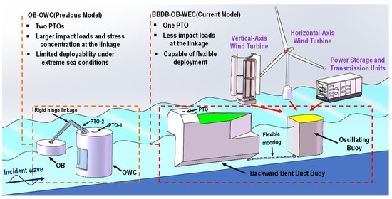
Figure 1.
Comparative schematic of OB-OWC and BBDB-OB hybrid system.
This study is based on the hypothesis that key parameters, including nozzle ratio (NR), coupling distance between buoys, draft, buoy geometry, and motion configurations, have a significant relationship with the hydrodynamic efficiency of the hybrid system, thereby providing practical guidance for optimizing the BBDB-OB hybrid system. To this end, a flared BBDB and buoy models with spherical, cylindrical, and semi-capsule shapes were designed and tested in a wave flume under both regular and irregular wave conditions. Comparative analyses were conducted across multiple configurations to assess the dynamic responses and power conversion characteristics. These research questions are justified because previous studies have primarily addressed OB-OWC hybrids with rigid connections and idealized numerical models, neglecting the performance implications of flexible coupling and actual wave conditions. These findings aim to provide valuable insights into the coupling mechanism and geometric optimization of hybrid WEC systems with enhanced energy capture and operation adaptability.
2. Physical Model Approach
2.1. Experimental Setup of the BBDB-OB Model
The experimental workflow is shown in Figure 2. Initial tests focused on optimizing the PTO output of BBDB by evaluating the effects of nozzle ratio and airflow mode. The BBDB–OB hybrid system with flexible mooring was subsequently tested to examine the influence of coupling distance, motion configuration, buoy geometry, and draft depth. The entire experimental program was designed to enhance hydrodynamic efficiency and wave energy capture performance.
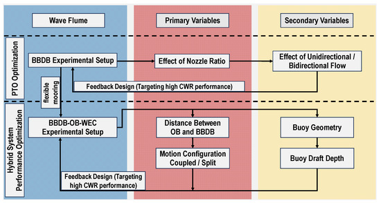
Figure 2.
Flowchart of the experimental program.
The experimental study was conducted in the narrow wave flume at the Guangzhou Institute of Energy Conversion, China. The wave-making apparatus incorporated a servo motor-driven push-plate mechanism with a frequency converter control, allowing precise manipulation of hydrodynamic parameters. It was capable of generating both regular and irregular waves. The wave flume used in this study is identical to that employed in previous experiments; the main dimensions and the physical model used for testing are shown in Figure 3 [49]. The wave flume was 56.0 m long, 1.2 m wide, and had a maximum water depth of 1.2 m. A wave-absorbing area was set up at the opposite end of the wave maker. Two digital wave height gauges were installed at distances of 6 m and 20 m from the wave board to measure the wave height and period data of the incident and reflected waves, respectively.

Figure 3.
Sketch of the experimental set-up and the physical model in the wave flume (adapted from [49]).
The BBDB-OB-WEC, consisting of a BBDB and a floating buoy, was installed along the central axis of the flume. During the experiment, the net water depth was set to 0.95 m. The scaled model was placed on the centerline of the flume, 20.0 m from the wave maker. A Cartesian coordinate system (Oxz) was established with the origin (O) at the center of the free surface inside the chamber when the backward-bent duct buoy floated on the water surface. The positive direction of the x-axis corresponded to the incident wave propagation direction, while the positive z-axis pointed upwards in the direction of wave elevation. The sensors and data acquisition devices used in the experiment are listed in Table 1.

Table 1.
Experimental sensors and data acquisition equipment.
In accordance with the gravitational similarity criterion, an energy capture model with a 1:10 scale ratio was employed in the experiment. The model consisted of three parts: the BBDB model, the oscillating buoy, and the mooring system. The BBDB model was mainly constructed from aluminum plates and acrylic panels. Aluminum plates were chosen for their ease of manufacturing and mechanical strength, which ensured the structural integrity of the model. The L-shaped acrylic panels on the sides allowed for direct observation of the free surface movement inside the chamber and the flow within the horizontal duct, owing to their transparency. As illustrated in Figure 4, which depicts the BBDB model and the flexible mooring connection to the floating buoy within the wave flume of the hybrid system, rubber gaskets were placed between the acrylic panels and aluminum plates to ensure airtightness, and the components were secured with screws to maintain a reliable seal.
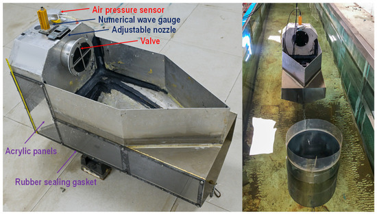
Figure 4.
View of the BBDB model and hybrid system floating in the flume.
The size parameters and perspective diagram of the horizontally flared pentagonal BBDB model are shown in Figure 5. The model consists of a rectangular chamber, an L-shaped duct, a buoyancy cabin, and a valve. The chamber width, representing the capture width of the model and noted as B, measures 0.4 m. The draft of the device is also shown as the red line in Figure 5, measuring 0.36 m. The chamber length is 0.2 m, giving a chamber area of 0.08 m2. One part of the chamber was submerged in water, while the other part was filled with air and connected to the atmosphere. The horizontally oriented flow channel of the L-shaped duct was designed as a flared duct, featuring a gradual expansion from the inlet to the outlet. The outlet side, along the x-axis cross section, formed a pentagon, while the side near the air chamber, along the x-axis cross section, formed a parallel concave hexagon with an area equal to the chamber cross-sectional area. The entire duct was completely submerged in water, with the two edges at the bottom of the x-axis cross-section intersecting at an angle of 120°. A valve with a diameter of 130 mm was installed on the side of the air chamber to control the airflow inside the chamber, allowing for either unidirectional or bidirectional flow. This feature enabled adjustments to the working mode of the backward-bent duct. The overall dimensions of the model are 0.95 m × 0.40 m × 0.60 m. After installing sensors and counterweights, the total mass of the model reached 20.35 kg. The primary parameters of the model considered in this study are summarized in Table 2.
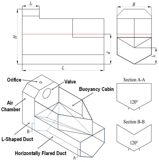
Figure 5.
Sketch of the dimension and perspective diagram of the flared BBDB.

Table 2.
Main parameters of the flared BBDB model.
The effect of an air turbine was typically simulated by using an orifice or a layer of porous material in the OWC model. In this study, a specially designed circular orifice with an adjustable nozzle ratio was installed at the top of the chamber. The orifice consisted of an acrylic plate with a 39 mm diameter circular hole, accompanied by two sliding blocks with serrated seals. This configuration was developed to simulate varying turbine damping conditions during the experiment. The configurations of the adjustable orifice in both fully open and fully closed states were illustrated in Figure 6.
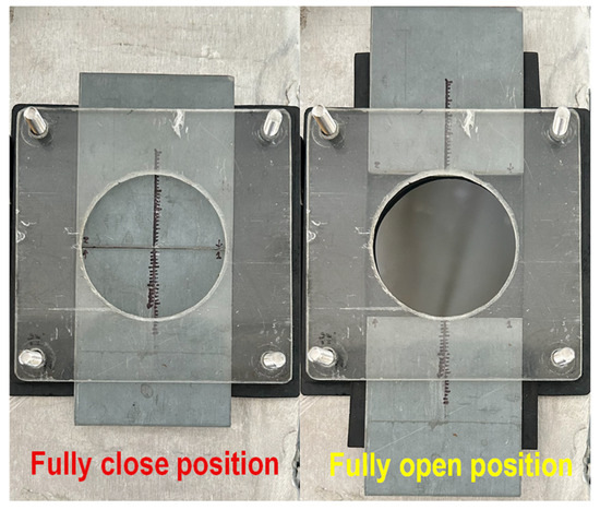
Figure 6.
Schematic view of the orifice with an adjustable nozzle.
For the oscillating buoy in the system, three geometric shapes of floating buoys were designed for this study: spherical buoy, cylindrical buoy, and semi-capsule-shaped buoy. The capture width in wave facing direction for each buoy model was set to 0.3 m. The spherical buoy model was made of plastic with a hollow internal structure, while the cylindrical and semi-capsule-shaped buoy models were fabricated from galvanized steel plates. The schematic diagrams of the three buoy models are shown in Figure 7, and the main parameters of each buoy are listed in the table. To investigate the influence of buoy shape on the primary conversion efficiency of the systems, the three different buoy models were connected to the model through mooring chains. The main parameters of different buoy models considered in this work are summarized in Table 3.
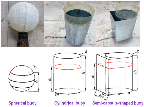
Figure 7.
Schematic diagrams of three buoy models.

Table 3.
Main parameters of the three buoy models.
2.2. Data Processing Method
For calculating the CWR of the model, which is the ratio of the pneumatic power to incident wave power, as follows:
where Pair is the pneumatic power. Preg is the incident regular wave power. Pirr is the incident irregular wave power.
where ρ is the water density, ρ = 1000 kg/m3. g is the gravitational acceleration. h is the water depth. B is the model width. Cg is the wave group velocity. The wave number k and phase velocity c can be obtained by solving the dispersion relation to determine the wavelength L. The definitions of the average wave period and average wave height are as follows:
The number of data points N corresponds to the number of measurements collected within the selected time period of the experiment. The average wave power of irregular incident waves is calculated using the following formulas, where and represent the average period and significant wave height of the irregular incident wave, respectively.
The calculation of pneumatic power depends on the type of work performed by the water column inside the chamber, which drives the airflow. When a unidirectional valve is installed in the air chamber, allowing air to flow unidirectionally through the nozzle, the pneumatic power of the model can be expressed as follows:
where and are the water level inside at time steps i + 1-th and i-th sampling, respectively. S signifies the cross-sectional area of the chamber’s waterline surface, and n denotes the total number of samplings. When the valve is closed, allowing air to flow bidirectionally through the nozzle, the pneumatic power of the device can be expressed as follows:
3. Results Evaluation and Discussion
3.1. Effects of the Nozzle Ratio
The nozzle ratio is a critical parameter influencing the wave energy conversion efficiency of the system. An optimal nozzle diameter must be designed by balancing airflow and pressure during operation to maximize energy transfer. In this section, the hydrodynamic efficiency of the BBDB-OB hybrid system, in which only the BBDB is considered, is analyzed under different nozzle ratios. Additionally, the variation of water column elevation and air pressure inside the chamber is compared. NR represents the ratio of the chamber’s cross-sectional area A to the orifice area .
The BBDB was operated under a draft of 0.34 m, with unidirectional airflow driven by the air chamber during energy conversion. As presented in Table 4, the experiments were divided into five test groups, in which regular waves with a constant wave height of 0.05 m and varying wave periods ranging from 0.9 s to 1.6 s were used to evaluate five different nozzle ratios.

Table 4.
The peak CWR of BBDB under different nozzle ratios.
Figure 8 presents five sets of experimental data capturing the air pressure inside the chamber and the free surface elevation at time domain intervals during the stable operation phase of the device. As shown by the strong blue curve in Figure 8, the chamber with NR = 80 exhibits the lowest peak air pressure and the largest relative variation in free surface elevation. In contrast, the light red curve for NR = 140 indicates the highest air pressure with the smallest fluctuation in water surface elevation. Those observations suggest that a smaller NR facilitates airflow under short-period wave conditions, reducing damping effects and enabling a more unrestricted oscillation of the water column. Conversely, a larger NR enhances pressure differentials under longer-period waves, thereby improving the PTO efficiency. The motion of the water column is limited by excessive damping, and the resonance is shifted toward longer wave periods. Figure 9 illustrates the variation of the capture width ratio (CWR) of the BBDB device across different wave periods for five experimental configurations. It is evident that the nozzle ratio has a considerable influence on both the resonant period and the peak CWR. As the NR increases, the peak efficiency shifts from 1.20 s to 1.30 s, with the corresponding CWR enhanced by 49.18%.
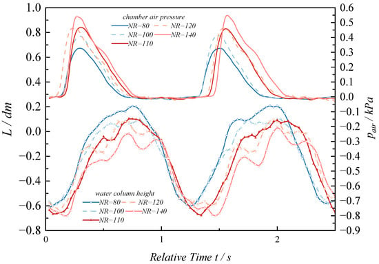
Figure 8.
Comparison of the water column height and air pressure data within the chamber under different nozzle ratios.
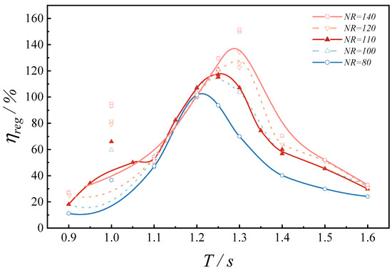
Figure 9.
Variation of the CWR of BBDB under different nozzle ratios.
Although higher NR effectively increases the pressure amplitude, it also induces stronger free surface oscillations. The strong blue curve in Figure 8 displays an approximately sinusoidal variation indicative of piston-like motion, while the light red curve exhibits superimposed high-order oscillations, implying that the internal displacement of the water column transitions from the desired “piston” mode to a “sloshing” mode. In related studies on central-duct OWC devices, Zhou et al. [50] observed that such sloshing behavior typically develops in the circumferential direction, and the modal analysis revealed that first-order modes result in asymmetrical elevation profiles along the x-axis. Under second-order modal excitation, two high and two low amplitude regions form along the circumference, manifesting in a complex sloshing state that may introduce additional energy dissipation. In the present experiments, direct visual observations through the transparent acrylic side panel revealed asymmetric elevations on either side of the water column, resembling a first-order axial mode. Despite significant oscillation in wave gauge measurements, the actual volume change was limited, and the asymmetric free surface introduced measurement errors that compromised the accuracy of hydrodynamic efficiency calculations. Moreover, the sloshing surface hindered the effective transmission of captured wave energy to the air column within the chamber.
Under piston-type displacement conditions of the water column, the BBDB chamber, operating at NR = 110, exhibited significant air pressure fluctuations and pronounced relative free surface elevation during the unidirectional airflow mode. The corresponding efficiency spectrum as a function of wave period T is presented in Figure 10. In this case, the CWR peaked at 117.72% at T = 1.25 s under unidirectional airflow. In comparison, bidirectional airflow yielded a higher CWR of 127.24% at T = 1.30 s. Notably, under identical nozzle configurations, the bidirectional airflow mode achieved superior energy conversion efficiency in the resonant range of 1.25 s < T < 1.30 s. Furthermore, the slope of the CWR fitting curve declines more gradually on either side of the peak, indicating better bandwidth and hydrodynamic performance under both low-frequency and high-frequency wave conditions. Additionally, the free surface oscillations inside the chamber during bidirectional airflow were observed to be reduced compared to those under unidirectional airflow, motivating further investigations based on the NR = 110 bidirectional airflow condition. Notably, a significant discrepancy exists between the data at T = 1.10 s, which may be attributed to the influence of drift force under short-period wave excitation [27], leading to transverse sloshing mode and deviations in wave gauge measurements.
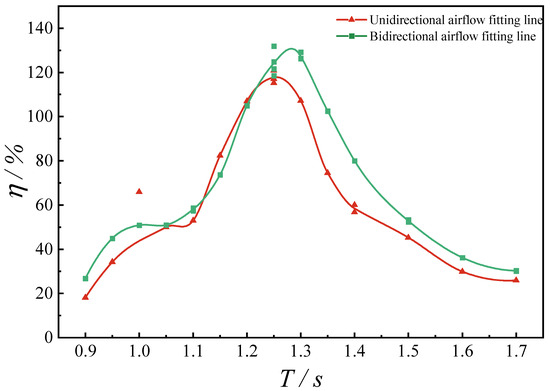
Figure 10.
Comparison of CWR under unidirectional and bidirectional airflow.
3.2. Effect of Distance Between OB and OWC
In the present section, a spherical buoy was employed as a heaving point absorber and was flexibly moored to the BBDB to examine how the distance between the OB and the BBDB affects wave energy conversion efficiency. Six distinct non-dimensional distance ratios 0.316, 0.421, 0.526, 0.632, 0.737, and 0.842, defined as the ratio of the distance between two devices to buoy diameter, were considered. The experiments were conducted at NR = 110, capture width ratio , under bidirectional airflow conditions. The variation of CWR with respect to the incident wave period T for different OB-BBDB distances is presented in Figure 11.
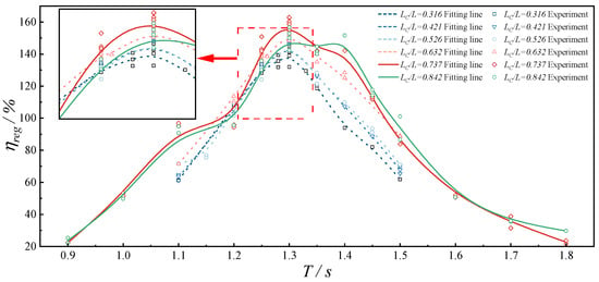
Figure 11.
Variation of CWR with wave periods T for different distances.
As shown in Figure 11, the energy conversion performance of the moored BBDB-OB hybrid system was found to be significantly influenced by the distance . An increase in distance resulted in a gradual improvement in peak CWR. Specifically, for distance ratios of 0.632, 0.737, and 0.842, the peak efficiency exceeded 150%, and the maximum observed CWR reached 160.39% at the wave period T = 1.30 s. Within the interval 1.25 s < T < 1.35 s, all configurations exhibited significant efficiency peaks, indicating that the system demonstrated optimal wave attenuation capacity in this range. All setups attained their respective maximum CWR values at T = 1.30 s, indicating that the BBDB and OB were operating at resonant frequency, thus decreasing wave energy dissipation while maximizing energy absorption efficiency.
For the sake of comparative analysis of peak period performance and the influence of reflected waves from the buoy at varying distances, supplementary experiments were conducted to assess the capture width ratio of the hybrid system at peak period T = 1.30 s under two distinct conditions: and a decoupled BBDB-OB system under the unmoored split configuration. As depicted in Figure 12, the capture width ratio of the hybrid system initially increased as the distance interval widened, reaching a maximum , then declined as the distance was further increased. This trend indicates the presence of a critical distance near , at which the heave motions of the BBDB and the floating buoy exhibited a phase opposition. Under these circumstances, the incident wave and the radiated wave from the BBDB constructively interfered, boosting the resonant response effected on the floating buoy. The enhanced motion of the buoy transmitted through the mooring chain effectively augmented the surge and pitch motions of the BBDB, leading to improved energy absorption. The buoy was displaced from the constructive interference zone and entered a complex wave field dominated by BBDB-generated disturbances as the distance was reduced below . The shortened mooring length imposed increased stiffness due to taut catenary geometry, inducing nonlinear high-frequency oscillations that impaired the system’s energy-capturing stability. On the contrary, the wave excitation acting on the buoy diminished when the distance exceeded . The increased deformation and friction within the mooring chain introduced greater damping into the coupled system, resulting in a lower peak efficiency [51]. Notably, at , a secondary peak in CWR was observed at T = 1.40, where the CWR surpassed that of . Furthermore, the effective capture bandwidth beyond the peak period was broadened, indicating that reduced mooring stiffness at this spacing improved low-frequency motion response. The system thus exhibited enhanced coupling between low-frequency dynamics and wave forcing, allowing for improved absorption of long-period waves under this configuration.
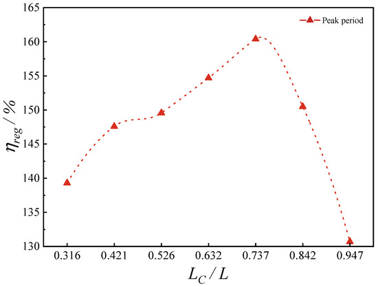
Figure 12.
Variation in CWR of the hybrid system at the peak period across different distance configurations between BBDB and OB.
Figure 13 presents the efficiency curves under three different configurations: (i) coupled motion of BBDB and the floating buoy via mooring connection at ; (ii) decoupled or split motion without mooring connection between the floating buoy and BBDB, and (iii) the BBDB operating independently without the presence of a buoy. It is evident that the hybrid system under moored coupling exhibits a substantial improvement in both peak CWR and effective energy capture bandwidth compared to the split-motion configuration. In contrast, the efficiency curve of the hybrid system operating in split motion closely follows the trend observed for the BBDB alone. This indicates that the radiated waves generated by the oscillating buoy have a limited influence on the hydrodynamic damping experienced by the BBDB at . Consequently, the enhancement in CWR due to the presence of the radiation effect generated by the floating buoy is marginal when the system operates without mechanical coupling.
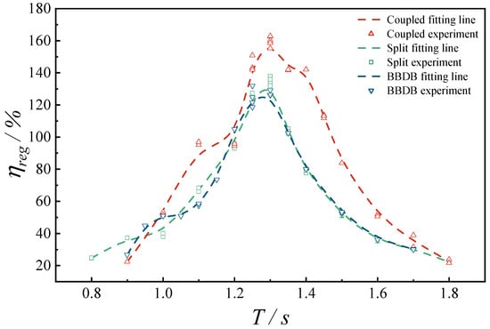
Figure 13.
Variation of CWR of the hybrid system with incident wave period under three different motion configuration modes.
3.3. Effects of the Spherical Floater Draft
The influence of the spherical buoy draft on the CWR of the hybrid system was examined in this section. As shown in Figure 14, circumstances were conducted under three draft conditions: the ratio of draft to buoy radius R , varied from 1.2 to 1.6 with an interval of 0.2, while maintaining a constant distance ratio at , NR = 110 and the d = 0.05 m. Evident variations in system efficiency were observed as the draft was altered. Resonant frequency remained largely unaffected by changes in floater draft. However, effective capture bandwidth was found to increase initially and then decline with deeper immersion. This trend could be explained by contrasting hydrodynamic behaviors, as shallower buoys experienced enhanced radiation damping, which reduced heave amplitude; deeper buoys induced greater added mass, thereby strengthening inertial responses under long-period waves and reducing overall efficiency. Maximum performance was achieved at a ratio of approximately , where damping and inertial effects reached an optimal balance.
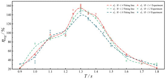
Figure 14.
Variation in CWR of the hybrid system floater with three different draft conditions.
3.4. Influence of Motion Configuration in Irregular Waves
The hydrodynamic performance of the wave energy converter under irregular wave conditions was evaluated across three distinct motion configurations: (i) a coupled motion configuration wherein the spherical buoy was moored to the BBDB (BBDB–OB coupled), (ii) a decoupled configuration without mooring connection (BBDB–OB split), and (iii) a solo BBDB configuration absent the spherical buoy (BBDB independent). The experimental parameters were maintained constant with a nozzle ratio of NR = 110, BBDB draft d = 0.05 m, spherical buoy draft , and normalized distance between the BBDB and buoy fixed at . As depicted in Figure 15, experimental investigations were conducted under irregular wave conditions characterized by a significant wave height of 0.05 m and effective wave periods ranging from 0.9 s to 1.85 s. The experimental results demonstrated that the BBDB-OB hybrid system under a compliant mooring connection exhibited substantially improved hydrodynamic efficiency compared to alternative configurations. A maximum CWR of 107.99% was attained at the spectral peak period s, accompanied by a broader effective bandwidth.
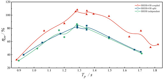
Figure 15.
CWR of the hybrid system under irregular waves with three different motion configurations.
Conversely, the hydrodynamic efficiencies of the split and independent configurations presented minimal variation, indicating that under irregular wave excitation, the reciprocal response of the spherical buoy imparted negligible influence on the dynamic behavior of BBDB. The compliant mechanical coupling provided by the mooring chain effectively facilitated axial force transmission between the two bodies, thereby augmenting the overall hydrodynamic performance of the coupled hybrid system.
3.5. Effect of Floater Geometry
To evaluate the influence of buoy geometry on wave energy extraction performance, three distinctly shaped buoys were considered for the hybrid system: a spherical buoy, a cylindrical buoy, and a semi-capsule-shaped cylindrical buoy (characterized by a semi-capsule profile in the top view). All buoys maintained an identical incident capture width dimension . The ratios of draft to radius were established as follows: for the spherical buoy, for the cylindrical buoy, and for the semi-capsule-shaped buoy. The normalized separation distance between each buoy and the BBDB was consistently maintained at . Figure 16 presents the variation in CWR across the three geometric configurations under regular wave conditions, with incident wave periods ranging from 0.9 s to 2.2 s and a constant wave height of 0.05 m. Within the intermediate period range of 1.20 s < T < 1.45 s, the hybrid systems incorporating cylindrical and semi-capsule-shaped buoys demonstrated superior energy conversion efficiency compared to the spherical buoy configuration. Notably, the hybrid system with the semi-capsule-shaped buoy attained a maximum CWR of 176.69% at T = 1.30 s, marginally exceeding that of the cylindrical counterpart. This performance enhancement can be attributed to the geometric asymmetry of the semi-capsule profile, which generated a more distinct axial pressure differential. Additionally, the semi-capsule buoy was accompanied by coupled pitch motion while reaching the heave resonance, which contributed significantly to enhanced wave energy absorption within the hybrid system.
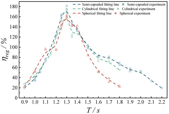
Figure 16.
Variation in CWR across the three geometric configurations under regular wave conditions.
Furthermore, experimental results indicated that the semi-capsule buoy maintained superior hydrodynamic response characteristics within the wave range of 1.45 s < T < 2.20 s, resulting in an extended effective bandwidth. This observation suggested that the asymmetric geometry not only amplified peak performance metrics but also enhanced the adaptability to a wider range of wave frequency conditions.
4. Conclusions
In this study, a novel hybrid wave energy converter concept was proposed, referred to as the BBDB-OB-WEC system, which integrated a horizontally flared pentagonal BBDB and a tailing floating oscillating buoy connected to the stern via a flexible mooring chain, sharing a common PTO mounted on the BBDB. A comprehensive experimental investigation was then conducted to evaluate the hydrodynamic performance and energy harvesting of this hybrid system. Multiple influencing parameters, including nozzle ratio, coupling distance, floater draft, and floater geometry under the regular incident waves, were systematically examined and analyzed to reveal the energy conversion characteristics. Further, the motion configuration under both regular and irregular waves was carried out in the flume experiment.
There exists an appropriate nozzle ratio that significantly enhances the primary energy conversion efficiency. A smaller nozzle ratio facilitates airflow under short-period wave conditions, while a larger nozzle ratio contributes to enhanced hydrodynamic efficiency under long-period wave conditions, with a transition from piston-type to sloshing-type motion in the water column observed at higher nozzle ratios. A nozzle ratio of 110 provides the optimal balance between air pressure differential and water column displacement, especially under bidirectional airflow, thereby expanding the effective frequency bandwidth.
The coupling distance between the BBDB and the OB exhibits a critical influence on CWR of the hybrid system, with peak efficiency exceeding 160% observed near a normalized distance of 0.737 during the resonance period. Efficiency declines due to mechanical damping and phase mismatch when the spacing deviates from this value. The drafts of floaters also influence low-frequency responsiveness, with intermediate drafts offering the best balance between radiation damping and added mass. Under both regular and irregular wave conditions, the hybrid system, mechanically coupled through a mooring chain, significantly outperforms decoupled configurations in terms of hydrodynamic efficiency and effective frequency bandwidth. The CWR of BBDB is slightly affected by the floating buoy within a relatively confined range, while the compliant mechanical link provided by the mooring connection effectively transmits axial tensile forces between the two components. Additionally, buoy geometry proves to be a decisive factor influencing power absorption and overall efficiency, with asymmetric semi-capsule-shaped bodies delivering peak efficiencies exceeding 170, exhibiting favorable response under long-period wave conditions. This configuration significantly enhances the effective wave energy capture bandwidth of the hybrid system.
This experimental investigation on the BBDB-OB-WEC hybrid system aims to prompt the integration of the BBDB with an OB to enhance overall wave energy absorption and expand the operational bandwidth of the device. However, the current study is limited by the use of a narrow wave flume and the lack of a comprehensive analysis of the mooring system within the hybrid configuration. Therefore, future studies should incorporate the development of a nonlinear numerical model for the BBDB-OB hybrid system, supported by a larger physical model testing and three-dimensional CFD simulations, to evaluate the integrated power extraction performance and the dynamic behavior of the mooring system.
Author Contributions
P.L.: configuration proposal, investigation, model test, software, data analysis, and writing—original draft. X.R.: model test, software, data analysis, and writing—reviewing and editing. B.W.: conceptualization, funding acquisition, methodology, formal analysis, project administration, and validation. Z.Y.: model test and data analysis. F.Z.: software. All authors have read and agreed to the published version of the manuscript.
Funding
The authors gratefully thank the financial support from the National Natural Science Foundation of China (NO. U20A20106 and NO. 51879253).
Data Availability Statement
Data will be made available on request.
Conflicts of Interest
The authors declare no conflicts of interest.
References
- United Nations Department for Economic and Social Affairs World Population Prospects 2024: Summary of Results; United Nations: New York, NY, USA, 2025; ISBN 978-92-1-003169-1.
- Krane, J. Climate change and fossil fuel: An examination of risks for the energy industry and producer states. MRS Energy Sustain. 2017, 4, E2. [Google Scholar] [CrossRef]
- Ritchie, H.; Roser, M. CO2 and Other Greenhouse Gas Emissions. Our World Data 2017. Available online: https://ourworldindata.org/co2-and-greenhouse-gas-emissions (accessed on 29 July 2025).
- Hassan, Q.; Viktor, P.; Al-Musawi, T.J.; Mahmood Ali, B.; Algburi, S.; Alzoubi, H.M.; Khudhair Al-Jiboory, A.; Zuhair Sameen, A.; Salman, H.M.; Jaszczur, M. The renewable energy role in the global energy Transformations. Renew. Energy Focus 2024, 48, 100545. [Google Scholar] [CrossRef]
- Gunn, K.; Stock-Williams, C. Quantifying the global wave power resource. Renew. Energy 2012, 44, 296–304. [Google Scholar] [CrossRef]
- Rusu, L.; Rusu, E. Evaluation of the Worldwide Wave Energy Distribution Based on ERA5 Data and Altimeter Measurements. Energies 2021, 14, 394. [Google Scholar] [CrossRef]
- Falnes, J. A review of wave-energy extraction. Mar. Struct. 2007, 20, 185–201. [Google Scholar] [CrossRef]
- Samsó, R.; Crespin, J.; García-Olivares, A.; Solé, J. Examining the potential of marine renewable energy: A net energy perspective. Sustainability 2023, 15, 8050. [Google Scholar] [CrossRef]
- Fredriksen, A. Tapered channel wave power plants. In Energy for Rural and Island Communities; Elsevier: Amsterdam, The Netherlands, 1986; pp. 179–182. [Google Scholar]
- Kofoed, J.P.; Frigaard, P.; Friis-Madsen, E.; Sørensen, H.C. Prototype testing of the wave energy converter wave dragon. Renew. Energy 2006, 31, 181–189. [Google Scholar] [CrossRef]
- Heath, T. The development and installation of the LIMPET Wave Energy Converter. In World Renewable Energy Congress VI; Elsevier: Amsterdam, The Netherlands, 2000; pp. 1619–1622. [Google Scholar]
- Falcão, A.F.; Sarmento, A.J.; Gato, L.M.; Brito-Melo, A. The Pico OWC wave power plant: Its lifetime from conception to closure 1986–2018. Appl. Ocean Res. 2020, 98, 102104. [Google Scholar] [CrossRef]
- Evans, D.V.; Porter, R. Efficient calculation of hydrodynamic properties of OWC-type devices. J. Offshore Mech. Arct. Eng. 1997, 119, 210–218. [Google Scholar] [CrossRef]
- Sarmento, A.J.; Falcão, A.F.d.O. Wave generation by an oscillating surface-pressure and its application in wave-energy extraction. J. Fluid Mech. 1985, 150, 467–485. [Google Scholar]
- Elhanafi, A.; Macfarlane, G.; Fleming, A.; Leong, Z. Scaling and air compressibility effects on a three-dimensional offshore stationary OWC wave energy converter. Appl. Energy 2017, 189, 1–20. [Google Scholar] [CrossRef]
- Gong, S.; Gao, J.; Yan, M.; Song, Z.; Shi, H. Effects of floater motion on wave loads during steady-state gap resonance occurring between two non-identical boxes. Ocean Eng. 2025, 323, 120649. [Google Scholar] [CrossRef]
- Song, Z.; Jiao, Z.; Gao, J.; Mi, C.; Liu, Y. Numerical investigation on the hydrodynamic wave forces on the three barges in proximity. Ocean Eng. 2025, 316, 119941. [Google Scholar] [CrossRef]
- Mi, C.; Gao, J.; Song, Z.; Liu, Y. Hydrodynamic wave forces on two side-by-side barges subjected to nonlinear focused wave groups. Ocean Eng. 2025, 317, 120056. [Google Scholar] [CrossRef]
- Li, B.; Li, C.; Zhang, B.; Deng, F.; Yang, H. The effect of the different spacing ratios on wave energy converter of three floating bodies. Energy 2023, 268, 126696. [Google Scholar] [CrossRef]
- Masuda, Y. Experiences in pneumatic wave energy conversion. Util. Ocean. Waves-Wave Energy Convers. 1986, 1986, 1–33. [Google Scholar]
- Masuda, Y.; Kuboki, T.; Ravindrum, M.; Pathak, A.; Jayashankar, V.; Liang, X. Development of backward bent duct buoy (BBDB). In Proceedings of the ISOPE International Ocean and Polar Engineering Conference, Brest, France, 30 May–4 June 1999; ISOPE: Brest, France, 1999; p. ISOPE-I-99-023. [Google Scholar]
- Masuda, Y.; Yamazaki, T.; Outa, Y.; McCormick, M. Study of backward bent duct buoy. In Proceedings of the OCEANS′87, Halifax, NS, Canada, 28 September–1 October 1987; pp. 384–389. [Google Scholar]
- Nagata, S.; Imai, Y.; Toyota, K.; Isshiki, H. Thrust generation by waves. In Proceedings of the Ninth ISOPE Pacific/Asia Offshore Mechanics Symposium, Busan, Republic of Korea, 14–17 November 2010; ISOPE: Beijing, China, 2010; p. ISOPE-P-10-057. [Google Scholar]
- Imai, Y.; Toyota, K.; Nagata, S.; Setoguchi, T.; Oda, J.; Matsunaga, N.; Shimozono, T. An experimental study of negative drift force acting on a floating OWC “backward bent duct buoy”. In Proceedings of the International Conference on Offshore Mechanics and Arctic Engineering, Estoril, Portugal, 15–20 June 2008; pp. 871–879. [Google Scholar]
- Wu, B.-j.; Li, M.; Wu, R.-k.; Zhang, Y.-q.; Peng, W. Experimental study on primary efficiency of a new pentagonal backward bent duct buoy and assessment of prototypes. Renew. Energy 2017, 113, 774–783. [Google Scholar] [CrossRef]
- Sheng, W. Power performance of BBDB OWC wave energy converters. Renew. Energy 2019, 132, 709–722. [Google Scholar] [CrossRef]
- Portillo, J.; Reis, P.; Henriques, J.; Gato, L.; Falcão, A. Backward bent-duct buoy or frontward bent-duct buoy? Review, assessment and optimisation. Renew. Sustain. Energy Rev. 2019, 112, 353–368. [Google Scholar] [CrossRef]
- Liu, Z.; Zhang, X.; Xu, C. Hydrodynamic and energy-harvesting performance of a BBDB-OWC device in irregular waves: An experimental study. Appl. Energy 2023, 350, 121737. [Google Scholar] [CrossRef]
- Chen, W.; Xie, W.; Zhang, Y.; Wang, C.; Wang, L.; Huang, L. Improving wave energy conversion performance of a floating BBDB-OWC system by using dual chambers and a novel enhancement plate. Energy Conv. Manag. 2024, 307, 118332. [Google Scholar] [CrossRef]
- Rao, X.; Wu, B.; Liu, P.; Zhang, F.; Yuan, Z. High Conversion Efficiency of Oscillating-Buoy WEC with Pneumatic PTO: Principle Analysis and Experimental Verification. Renew. Energy 2025, 252, 123384. [Google Scholar] [CrossRef]
- Chen, T.; Wu, B.; Zhang, Y.; Long, Z.; Jiang, C.; Xiao, S.; Zhou, L.; Yang, Y. Experimental research on three parallel backward bent duct buoys. Ocean Eng. 2022, 265, 112573. [Google Scholar] [CrossRef]
- Hu, J.; Zhou, B.; Vogel, C.; Liu, P.; Willden, R.; Sun, K.; Zang, J.; Geng, J.; Jin, P.; Cui, L. Optimal design and performance analysis of a hybrid system combing a floating wind platform and wave energy converters. Appl. Energy 2020, 269, 114998. [Google Scholar] [CrossRef]
- Piscopo, V.; Benassai, G.; Cozzolino, L.; Della Morte, R.; Scamardella, A. A new optimization procedure of heaving point absorber hydrodynamic performances. Ocean Eng. 2016, 116, 242–259. [Google Scholar] [CrossRef]
- Wu, S.; Liu, C.; Chen, X. Offshore wave energy resource assessment in the East China Sea. Renew. Energy 2015, 76, 628–636. [Google Scholar] [CrossRef]
- Gao, H.; Xiao, J. Effects of power take-off parameters and harvester shape on wave energy extraction and output of a hydraulic conversion system. Appl. Energy 2021, 299, 117278. [Google Scholar] [CrossRef]
- Colling, J.K.; Jafari Kang, S.; Dehdashti, E.; Husain, S.; Masoud, H.; Parker, G.G. Free-decay heave motion of a spherical buoy. Fluids 2022, 7, 188. [Google Scholar] [CrossRef]
- Pastor, J.; Liu, Y. Frequency and time domain modeling and power output for a heaving point absorber wave energy converter. Int. J. Energy Environ. Eng. 2014, 5, 101. [Google Scholar] [CrossRef]
- Chen, Z.-f.; Zhou, B.-z.; Zhang, L.; Zhang, W.-c.; Wang, S.-q.; Zang, J. Geometrical evaluation on the viscous effect of point-absorber wave-energy converters. China Ocean Eng. 2018, 32, 443–452. [Google Scholar] [CrossRef]
- Berenjkoob, M.N.; Ghiasi, M.; Soares, C.G. Influence of the shape of a buoy on the efficiency of its dual-motion wave energy conversion. Energy 2021, 214, 118998. [Google Scholar] [CrossRef]
- Azam, A.; Ahmed, A.; Li, H.; Tairab, A.M.; Jia, C.; Li, N.; Zhang, Z. Design and analysis of the optimal spinning top-shaped buoy for wave energy harvesting in low energy density seas for sustainable marine aquaculture. Ocean Eng. 2022, 255, 111434. [Google Scholar] [CrossRef]
- Chen, F.; Duan, D.; Han, Q.; Yang, X.; Zhao, F. Study on force and wave energy conversion efficiency of buoys in low wave energy density seas. Energy Conv. Manag. 2019, 182, 191–200. [Google Scholar] [CrossRef]
- Weber, J.; Mouwen, F.; Parish, A.; Robertson, D. Wavebob—Research & development network and tools in the context of systems engineering. In Proceedings of the Eighth European Wave and Tidal Energy Conference, Uppsala, Sweden, 7–10 September 2009; pp. 416–420. [Google Scholar]
- Majidi, A.; Bingölbali, B.; Akpınar, A.; Iglesias, G.; Jafali, H. Downscaling wave energy converters for optimum performance in low-energy seas. Renew. Energy 2021, 168, 705–722. [Google Scholar] [CrossRef]
- Kim, J.; Kweon, H.-M.; Jeong, W.-M.; Cho, I.-H.; Cho, H.-Y. Design of the dual-buoy wave energy converter based on actual wave data of East Sea. Int. J. Nav. Archit. Ocean Eng. 2015, 7, 739–749. [Google Scholar] [CrossRef]
- Li, D.; Dong, X.; Borthwick, A.G.; Sharma, S.; Wang, T.; Huang, H.; Shi, H. Two-buoy and single-buoy floating wave energy converters: A numerical comparison. Energy 2024, 296, 131219. [Google Scholar] [CrossRef]
- Zheng, S.; Zhang, Y. Analytical study on wave power extraction from a hybrid wave energy converter. Ocean Eng. 2018, 165, 252–263. [Google Scholar] [CrossRef]
- Cui, L.; Zheng, S.; Zhang, Y.; Miles, J.; Iglesias, G. Wave power extraction from a hybrid oscillating water column-oscillating buoy wave energy converter. Renew. Sustain. Energy Rev. 2021, 135, 110234. [Google Scholar] [CrossRef]
- Wan, C.; Yang, C.; Bai, X.; Bi, C.; Chen, H.; Li, M.; Jin, Y.; Zhao, L. Numerical investigation on the hydrodynamics of a hybrid OWC wave energy converter combining a floating buoy. Ocean Eng. 2023, 281, 114818. [Google Scholar] [CrossRef]
- Rao, X.; Wu, B.; Liu, P.; Zhang, F. Experimental research on a novel OWC with two chambers separated by a buoyancy module. Ocean Eng. 2024, 307, 118106. [Google Scholar] [CrossRef]
- Zhou, Y.; Zhang, C.; Ning, D. Hydrodynamic investigation of a concentric cylindrical OWC wave energy converter. Energies 2018, 11, 985. [Google Scholar] [CrossRef]
- Zhang, H.; Elsakka, M.; Liu, B.; Xu, S.; Shi, H. Dynamic response characteristics of the taut mooring system for integrated renewable energy devices. Energy 2025, 322, 135729. [Google Scholar] [CrossRef]
Disclaimer/Publisher’s Note: The statements, opinions and data contained in all publications are solely those of the individual author(s) and contributor(s) and not of MDPI and/or the editor(s). MDPI and/or the editor(s) disclaim responsibility for any injury to people or property resulting from any ideas, methods, instructions or products referred to in the content. |
© 2025 by the authors. Licensee MDPI, Basel, Switzerland. This article is an open access article distributed under the terms and conditions of the Creative Commons Attribution (CC BY) license (https://creativecommons.org/licenses/by/4.0/).