Abstract
The aim of the article is to determine the control range of a multiphase squirrel cage induction generator with more than three stator phases, operating in a wide range of driving speeds. The generator produces an output DC voltage using a multiphase converter operating as a PWM rectifier. The entire speed range is divided into intervals in which the sequence of stator phase voltages and, in effect, the number of pole pairs, is changed. In each interval, the output voltage is regulated by the frequency and amplitude of the stator voltages causing the highest possible power efficiency of the generator. The system can be scalar controlled or regulated using field orientation. Generator characteristics are calculated based on the set of steady-state equations derived from differential equations describing the multiphase induction machine. The calculation results are compared with simulations and with the steady-state measurement of the vector-controlled nine-phase generator. Recognizing the reliability of the obtained results, calculations are performed for a twelve-phase generator, obtaining satisfactory efficiency from 70% to 85% in the generator speed range from 0.2 to 1.0 of the assumed reference speed of 314 rad/s. The generator producing DC voltage can charge an electrical energy storage system or can be used directly to provide electrical power. This solution is not patented.
1. Introduction
In works [1,2], it was shown that the multiphase induction machine, MIM, with the number of phases M > 3, controlled as an induction generator in the system of Figure 1, can generate the output voltage of a given value at large speed changes. This is due to the frequency control and step switching of the control sequence of the multiphase voltage source converter VSC operating as a PWM rectifier. The switching of the control sequence is carried out in the designated speed ranges. Then, the sequence of the MIM phase voltages changes and, consequently, so does the number of magnetic field poles of the generator. The physical description of multiphase induction generators was presented in [1].
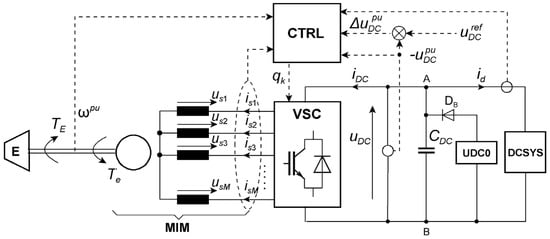
Figure 1.
General structure of the automatic uDC voltage control using multiphase induction machine, MIM, operating as the stator converter controlled squirrel cage induction generator. VSC—voltage source converter, E—driving engine, UDC0—system assuring a minimum voltage of CDC, DB—blocking diode, DCSYS—generator load on the DC side at the VSC output, CTRL—control system, ωpu—speed signal of the MIM related to the base reference speed Ωo, uDCref—DC bus voltage control signal, usk, isk—phase voltages and currents (k = 1, 2, …, M), qk—pulses controlling VSC.
This study aims to determine the operating conditions of a multiphase induction generator (IG) driven by a specified power PE = TEω at a speed ω varying over a wide range to regulate the output voltage uDC to a desired value and achieve the highest, near-constant energy efficiency. This solution is superior to other technical solutions for three-phase and multiphase induction generators.
Such MIM operation as an IG is possible when it has a special stator winding described in [1], called type 1. This winding is characterized by the fact that it generates magnetomotive force (MMF) harmonics of odd and even orders.
Another winding of type 2 produces only odd-order harmonics and is used in most multiphase induction motors and generators, e.g., [3,4,5,6,7,8,9,10,11,12,13]. These three-phase and multiphase IGs are mainly used in wind turbines as a part of wind energy conversion systems (WECSs). For a given stator voltage and frequency, such generators have a single mechanical characteristic. Voltage regulation in a DC link requires matching the frequency and stator voltage, which shifts the mechanical characteristic relative to speed. The lowest speed is limited by the ability to adjust the uCD voltage.
Induction generators such as squirrel cage (SCIG) and doubly fed (DFIG) are usually connected to the grid by the back-to-back converter. This converter connects the stator winding of a SCIG [6,14,15,16,17,18,19,20] and the rotor winding of a DFIG [14,20,21,22]. These solutions are dedicated to direct conversion of wind energy to the electrical for the power grid assuring the maximum power point tracking (MPPT) at varying generator speed to optimize wind turbine aerodynamic efficiency [6,16,17,21]. A quite different technical solution for MPPT of a wind turbine generating system without power electronic devices was presented in [23].
The topologies presented in [1,2,5,7,8,20,24,25,26] maintain the DC output voltage produced by SCIGs for the desired level. This voltage supplies the DC loading (DCSYS) that can be an energy storage system (ESS) [27], stand-alone power systems such as aircraft and vehicle (electric, hybrid, and traction), or the grid converter transferring the power. ESS systems can be created as supercapacitor connections, superconducting magnetic energy storage, flywheel, compressed air energy storage, pumped-storage hydroelectricity, li-ion batteries combined with solar, wind energy sources, etc. ESS can discharge stored energy during peak demand periods, assuring stability and reliability of electrical grids.
The increase in the speed range of the considered multiphase IG is illustrated schematically in Figure 2 against the background of the family of mechanical characteristics and characteristics of a driving engine.
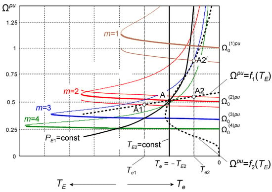
Figure 2.
Multiphase generator mechanical characteristics for the given voltage sequences m and characteristics of driving engines.
The generator characteristics are presented for four sequences of monoharmonic phase voltages having the same amplitude and frequency :
where . The voltage sequences are defined by the numbers m = 1, 2, 3, 4. The no-load speeds for these characteristics are expressed per unit relative to the mechanical basic reference speed for the number of pole pairs p and . The normalized characteristics are determined for the assumed stator frequency .
For the driving engine, two characteristic cases of mechanical power PE can be emphasized:
- -
- at PE = PE1 = const, the driving torque characteristic is described by the relationship ,
- -
- at = const, the driving power is , where Ω = ω = const.
A driving character similar to PE1 occurs when using a wind or water turbine, with the TE1 torque reaching a maximum at decreasing speed due to the change in the turbine power coefficient Cp [5,15,16,17,18,20,22]. PE2 may occur on the laboratory test stand of the generator or when the generator is driven by a diesel engine or during charging of hybrid vehicle batteries or regenerative braking of electric vehicles driven by a multiphase motor [13,28].
Point A of the operation was specially selected at the intersection of several characteristics. It corresponds to generator characteristic at the sequence m = 2, the mechanical characteristic of the driving engine , which is almost rigid (electric motor or combustion engine), and the flexible characteristic (wind turbine). Point A is also the maximum power point of the wind turbine. When the engine is loaded with the MIM at |Te1| > |Te|, the operating point assumes the position A1 for the almost rigid characteristic . However, this loading is too high for the wind turbine of the characteristic . For |Te2| < |Te|, the generator achieves two operating points: A2 for and A2′ for . Point A2 can be reached after a small increase in the frequency fs at the sequence m = 2, while point A2′ can be reached after a decrease in the frequency fs at the sequence m = 1 or after a significant increase in the frequency at m = 2. This example illustrates the problem of selecting the sequence number m and stator frequency range associated with the control block CTRL of the voltage ud. The additional criterion is the power efficiency of the generator at different speeds.
The power efficiency of a SCIG operating at a varying speed can be evaluated using equation between the mechanical driving power and the air-gap power . Output electrical power can be approximated, , where is the power loss as a sum of the iron loss and the copper loss [18,19]. Hence, the efficiency . Introducing rotor per unit frequency for the generator mode () and linear approximation of the mechanical characteristic stable part for (—characteristic slope), we obtain . As an example, we can assume = 0.04, = 1, = 0.1. For = 1, = 0.86, whereas for = 0.5, = 0.72, and for = 0.25, = 0.44. For decreasing generator speed , the efficiency decreases. This depends on the coefficient of the mechanical characteristic, the power loss , and the driving torque . However, at IG speeds lower than 0.5, maintaining the controlled voltage at a given level is practically impossible [25] (in practice, should be greater than 0.65). This is due to the limitation of the magnetic flux in the air gap caused by saturation. A similar phenomenon occurs in the case of a wound rotor synchronous generator at low speeds. It can be mentioned that DFIGs can work at a speed varying in the range of [14,21,22]. Thus, the use of a multiphase generator with a switchable number of poles via the sequence number m significantly increases the speed range at which the voltage can be regulated to a given value. This is discussed in Section 3.5.
The control system (CTRL) in Figure 1 is operating on the principle of scalar control [1] or field-oriented vector control [2]. This is schematically illustrated in Figure 3. For scalar control (Figure 3a), only the RU voltage regulator is used. The regulator is a PI type with saturation. The output signal is the relative rotor frequency . The stator frequency depends on the relative speed of MIM and the control sequence number m. The SEL block determines m for defined speed ranges. The GU block output generates signals , , , …, for the PWM controlling the VSC. These are monoharmonic signals in the form of voltages (1) referred to .
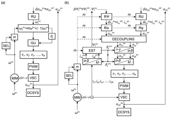
Figure 3.
Flow charts of the control block CTRL: (a) scalar control, (b) field-oriented control with respect to the rotor flux vector.
The CTRL block for vector control, shown in Figure 3b, is much more complex. The settings of the RU voltage regulator and the RΨ rotor flux vector regulator, as well as the Rix and Riy current regulators, depend on the sequence numbers m for which the MIM parameters are defined. Modulating signals , , , …, are generated at the output of the current regulators after decoupling the control paths x, y and orthogonal transformation. Details of the control system and real applications are presented in [2]. The settings of regulators are determined based on Kessler’s criteria. In this work, based on measurements, it is found that the steady-state control quality is similar in both control modes. In transient states, vector control enabled faster voltage regulation and smaller MIM torque peaks when switching the m number. More important, however, is the ability to regulate the voltage for a given value over a wider speed range than in the case of scalar control at a given m number.
The advantages of controlling the presented multiphase generators can be related to the following works, which are briefly described: [6]—six-phase IG (sliding mode control), [7]—five-phase IG (dual stator winding, DC generation system), [8]—five-phase IG (direct torque control DTC, DC generation system), [9]—six-phase IG (dual stator winding), [10]—nine-phase IG (two phase fault tolerance), [11]—six-phase IG (fuzzy control), [12]—three-phase IG (flux observer, stability analysis), [13] six-phase motor (fuzzy control and DTC), [14]—three-phase and six-phase IGs (VSC and current source converter CSC, matrix converter MC, various grid side converters), [15]—three-phase versus six-phase IGs (the DC generation system separately supplying the grid converter), [16]—three-phase IG (fuzzy control), [17]—three-phase IG (mechanical model of a wind turbine), [18]—three-phase IG (loss minimization control), [19]—three-phase IG (modeling of iron losses), [21,22]—three-phase DFIGs, [23]—three-phase IG (electromagnetic frequency regulator eliminating the gear-box), [24]—three-phase IG (machine converter of new topology, DC generation system), [25]—three-phase IG, DC generation system), [29]—three-phase IG (wind turbine design). The stand-alone IG systems performing similar DC voltage regulation tasks as the proposed multiphase IG system were presented, among others, in [7,8,15,24,25]. However, for all the mentioned solutions, the minimum rotational speed cannot be lower than 0.5 of the rated or reference speed.
The presented multiphase IG can produce the desired voltage over a wider speed range by switching the sequence number m changing the pole pairs. The number of poles can be changed using a switchable stator winding [20]. The multiphase IG has only one winding allowing it to work with the number of pole pairs 1, 2, 3, 4, etc. When using a Dahlander winding in a three-phase machine, the number of pole pairs can be changed in a ratio of one to two. The greater number of poles can be obtained applying more windings in the stator. This is the worse solution for the machine magnetic core.
From the perspective of steady-state operation, it is important to determine the range of frequency, stator voltage, and m to obtain satisfactory voltage regulation over the widest possible speed range with the highest possible energy efficiency of the generator. The proposed method for determining the range of the generator control is based on differential equations of the multiphase generator solved in the steady state. Calculated characteristics indicate the range of control of the considered generator to obtain the highest power efficiency in the whole range of speed. Another method can be based on the simulation model formulated for the analyzed generating system. Then, computing steady states point by point, the characteristics can be determined. Additionally, the model of a driving engine, a gear box, and mechanical losses can be considered [5,18,30]. This method is laborious and does not provide a general overview of the situation, although the results are close to reality. It is similar to laboratory tests, which in practice can be performed for specific low-power multiphase generators [1,2].
This paper is organized in the following way. The multiphase cage induction machine mathematical model is presented in Section 2. This mathematical model comprises all the most important features of this machine. From the differential equations presented in Section 2.1, the steady-state equations presented in Section 2.2 are developed for monoharmonic stator voltages and monoharmonic currents. In such a case, the current vectors are predicted as particular integrals of a non-homogeneous equation system stating the steady-state solution. Hence, the equivalent circuit of the multiphase machine developed in Section 2.3 is utilized to determine the steady state characteristics. The studies of the model and multiphase generators steady-state properties are performed in Section 3. In Section 3.1, the parameters of the nine-phase generator are presented. In Section 3.2, there is an example of the nine-phase induction generator transient operation. In Section 3.3, the comparison of calculated and measured results is presented. In this way, the mathematical model and the adopted research method are verified. In Section 3.4, the characteristics of the twelve-phase induction generator are presented. As a result, the ranges of control for the greatest power efficiency at varying speed are determined. Section 3.5 explains the increase in efficiency of a polyphase generator due to switching sequence number m. Conclusions are given in Section 4. Analyzed generators are loaded with the DCSYS that is the resistance supplied by .
2. Mathematical Model and Steady-State Equations of an M-Phase Cage Induction Machine
2.1. Differential Equations
The circuit-oriented model of the M-phase induction machined is described by the differential equations and composed of winding resistances and inductances (self and mutual):
This mathematical model was formulated in [2] for the nine-phase induction machine, and here it is developed to the M phases. Further, these equations enable the formulation of the steady-state equations of the MIM operating as the multiphase SCIG. Then, the steady state characteristics can be determined and next the characteristics of power efficiency. Voltage Equation (2) for the M-phase multiphase induction machine has useful properties in symmetrical components presented below.
The vector of symmetrical components of voltages, currents, and flux linkages results from the respective phase quantities in vector after transformation by the use of matrix .
The transformation matrix (unitary and symmetrical) has the following form for a -phase system:
Instead of x, we must substitute voltage u, current i, and magnetic flux . For stator and for rotor , —number of rotor cage meshes (each mesh is composed by two bars and two end ring segments), —conjugation index. Pairs of symmetrical components are conjugated. Hence, the number of considered symmetrical components is
So, is for the stator and is for the rotor. The harmonic orders of the magnetic field are limited to the base values from the set . For ,
Omitting symmetrical components of zero sequence for a given and , the number of stator symmetrical components is and the number of rotor symmetrical components is . The stator voltage and current vectors of the equations have the following structure:
Symmetrical components of rotor currents are transformed into the stationary reference frame, associated with the stator assuming the following structure:
Numbers denote the stator or rotor symmetrical components. The matrix of mutual inductances contains magnetizing inductances defined for harmonic orders . The structure of this matrix shows that the machine model ignores magnetic couplings between the symmetrical components of the rotor, whereas the components , , are magnetically coupled with the stator current symmetrical component .
With such assumptions, numbers of the rotor symmetrical components are the same as the harmonic orders . The remaining parameters and matrices of the system of Equation (2) are related to the considered spectrum of field harmonics (7).
- –
- Matrix of coefficients for rotor rotational voltages contains numbers :
- –
- Matrix of stator resistances and the matrix of total stator inductances are as follows:
- –
- Matrix of rotor resistances and the matrix of total rotor inductances are as follows:
- The submatrices of rotor resistances and submatrices of total rotor inductances have similar structures:
- Describing and , the symbol should be replaced by , and when describing , it should be replaced by . Values of parameters in these matrices, depending on the machine design, can be calculated using the formulae shown below.
- –
- Description of parameters related to the machine design:
—harmonic order from the assumed set , μ0 = 4π × 10−7 H/m, —pole pair number, —stator inside diameter, —equivalent length of the machine core, —air gap equivalent length comprising the Carter’s factor, —number of stator phase turns, —stator winding factor, —rotor winding factor, —skew factor of the rotor cage.
- —resistance and leakage inductance of one ring segment of the rotor cage, respectively;
- —resistance and leakage inductance of one bar of the rotor cage, respectively;
- , —stator winding angles, —rotor cage skew angle, —number of coils in the group creating the phase winding.
The electromagnetic torque of the multiphase machine is described below with the transformation steps.
where —rotor rotation angle, —vector of stator phase currents, —vector of rotor cage mesh currents, —vectors stator and rotor currents after transformation to symmetrical components, —matrix of mutual inductances in the machine coordinates, —matrix of mutual inductances in symmetrical components. Substituting
we can express the electromagnetic torque for the given symmetrical component :
The machine electromagnetic torque is the sum of :
2.2. Steady-State Equations
The steady-state analysis of this machine is performed assuming monoharmonic stator voltages (1):
These voltages depend on the amplitude , the numbers determining all supply sequences and the phase angle corresponding to the angular frequency . Such a situation appears when using PWM for sinusoidal control of VSC. Then, impulse voltages appearing at these stator terminals are waveforms of sinusoidal average values. Therefore, the machine is analyzed as if it had sinusoidal voltages (neglected time higher harmonics). The machine speed is constant at a constant angular frequency of the stator voltages. For a given , the vector of stator voltage symmetrical components (8) assumes the form
Vectors , have only one non-zero element. The voltage components are for and for . The stator and rotor currents are monoharmonic. The solution of the differential Equation (2) can be performed as the superposition of solutions for and . So, the current vectors can be predicted as particular integrals of a non-homogeneous equation system:
For both voltage vectors, and , two solutions are obtained in the form of vectors , , , containing complex amplitudes of stator and rotor currents:
Vector contains only one non-zero element . Analysis of the structure (11) of matrix means that in the stator current vector only one symmetrical component is non-zero, whereas in vector three rotor symmetrical components with complex amplitudes , are non-zero. Thus, it is enough to solve the system of Equation (2) for to obtain the vectors , which yield the vectors , . Substituting and , into differential Equation (2), which means substitution of , , , we obtain the set of equations where the time-dependent factor is simplified (divided on both sides of the equal sign) and the system of steady-state equations assumes the following form:
for
where is given by (6) for . The system of Equation (35) is supplied with the stator voltage phasor . By introducing the rms value of stator voltage , the stator and rotor currents also take rms values and are times lower than those for .
The electromagnetic torque (29) of the machine assumes the following form for in the steady state:
for . for .
This torque is also the torque of the machine , because for symmetrical components with numbers the component torques are equal to zero.
Defining the relative slips of the machine
the set of steady state equations takes the form
2.3. Equivalent Circuit
From the set of Equation (39), the equivalent circuit of an M phase induction machine can be formulated. However, the same steady-state equations as (39) are obtained for the -phase induction machine with the symmetrical stator winding of the second type defined in [1]. The induction generator studied in [1,2] and presented above has the stator winding of the first type marked with the parameter . As it was mentioned, this winding is characterized by the fact that the harmonics of its magnetic field are of odd and even orders . The stator winding of the second type is marked with the parameter . This is characterized by the fact that the harmonics of its magnetic field are of odd orders . The presented Equation (39) can be adapted to the machine with a stator winding of the second type () by inserting in these equations the number instead of , because of the half-smaller number of harmonics of the magnetic field taken into account. The resulting equivalent circuit is presented in Figure 4.

Figure 4.
Equivalent circuit of an M-phase squirrel-cage induction machine.
Based on the equivalent circuit, the stator current can be expressed in terms of three rotor currents so as to express the torque in a different form.
Hence, the electromagnetic torque can be calculated using the following expressions:
By entering the relative stator frequency and the relative machine speed , the slips (38) can be described using a different formula. For simplicity, the relative stator frequency is designated . So
whereas the relative rotor frequencies related to the base stator frequency for a given can be expressed as the absolute rotor slips
Thus, the relative slips (38) have the form:
For a given frequency in (43), the machine speed can be expressed approximately as a straight line of the stable part of the mechanical characteristic
where is the no-load speed giving for (Figure 2), —slope of the characteristic for a given m.
The following basic reference units are adopted: (voltage), (current), (angular frequency), (power), (torque), where —stator phase rated voltage (rms), —stator phase rated current (rms), —stator rated frequency.
3. Range of Control Based on Steady State Characteristics
3.1. Parameters and Characteristics of the Nine-Phase Generator
The nine-phase induction machine has the stator winding presented in Figure 5. The mechanical characteristics of this machine are shown in Figure 6 for m = 1, 2, 3, 4 (36) and of the range 0, …, 1.2 at the constant supply rms voltage of the nominal frequency . For M = 9, the number (6) of considered supply sequences is = 4. The parameters of this machine are given in Table 1.
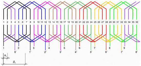
Figure 5.
Arrangement of the 9-phase winding with p = 1; beginnings of the phase windings: 1, 2, 3 …, 9 endings of the phase windings: 1′, 2′, 3′, …, 9′.
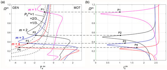
Figure 6.
Steady state characteristics of the 9-phase induction machine; (a) mechanical, (b) stator current; GEN—generator quadrant, MOT—motor quadrant.

Table 1.
Parameters of the analyzed M-phase induction machines.
The steady state characteristics show four points of operation when the generator is driven with the maximum power . For these points, the stator relative frequency is and the relative amplitude of phase voltage . The generator obtains these points due to the increase in the speed to , where is the absolute slip (43). For other speeds (45), the stator frequency must be increased or decreased with respect to . The slope coefficients read from the mechanical characteristics are (45): . When working in the GEN quadrant, we substitute for the speed in Figure 6. The determined values of are presented in Table 1.
3.2. Transient Operation of the Controlled Nine-Phase Generator
The multiphase generator usually works in steady state producing the desired voltage for (Figure 1). This generator can be scalarly controlled by the block CTRL presented in Figure 7. Computer simulation of this system for the nine-phase induction generator driven with variable speed was performed using the Simulink model presented in [31].
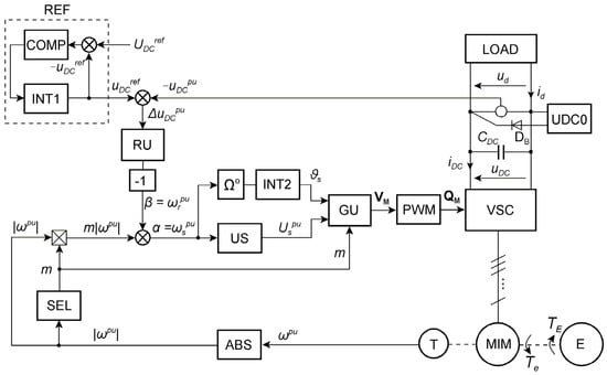
Figure 7.
Structure of the control system: REF—voltage reference network shaping uDCref as the ramp signal, COMP—comparator, INT1—signal ramp integrator, RU—voltage controller (PIsat—PI type with saturation), US—generator of voltage signal Uspu dependent on α = ωspu, INT2—integrator of stator frequency, GU—generator of M phase control signals, PWM—pulse width modulator, VSC—voltage source converter, ABS—absolute value changer, SEL—selector of supply sequence number m with respect of the MIM speed signal ωpu.
The Simulink model of the generating system was organized in the following way. The output terminals of VSC model were connected to nine current sources controlled with the stator phase currents. The sources were star connected. The voltages on these sources are the phase voltages of the generator mathematical model represented by the differential equations of Section 2.1. Such a coupling between currents and voltages is called “ideal transformer”. The MIM mathematical model was introduced to Simulink in the form of matrix operations of parameters and variables.
The results of simulations are presented in Figure 8. The control system operates satisfactorily with a linear speed change from 0.95 to 0.25 and up to 0.95. The desired DC voltage was for . Assuming the reference for the controlled voltage , the signal . In the analyzed cases, . The phase voltages were related to and the phase currents to . The LOAD circuit was a load resistance of . The voltage controller RU was of the PI type with saturation. The maximum absolute slip value = 0.1 corresponded to the saturation of the controller.
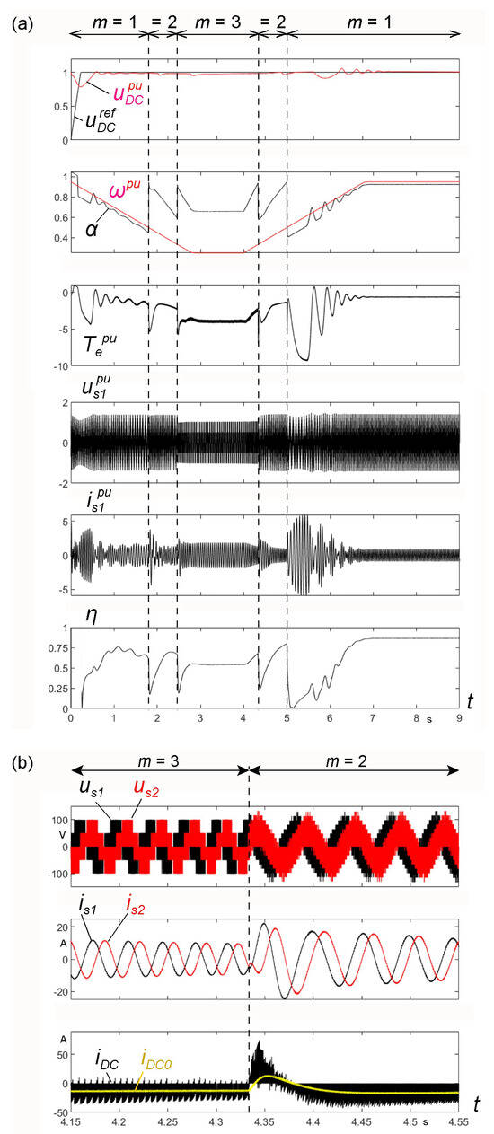
Figure 8.
Results of the generating system simulation with the 9-phase induction generator: (a) runs of the defined waveforms, (b) runs of voltages and currents in a chosen time interval.
During the change in the , the control sequence numbers m were set by the SEL system according to the following rules:
, then m = 3;
, then m = 2;
, then m = 1.
The system was not operated at m = 4 because the control system did not work properly at a high magnetizing current for this case (Figure 6).
The GU block generated the VM vector of signals controlling the MIM voltages using the pulse-width modulation method in the PWM block:
For the system from Figure 7, the following settings of the PI-type RU controller with saturation were used: saturation βmax = 0.1 resulting from the mechanical characteristics shown in Figure 6 and the coefficients from Table 1, gain KRU = βmax/(ΔUDCmax/UDCN), time constant TRU = CDC Rd. For ΔUDCmax = 0.75 V, UDCN = 150 V, KRU = 20. For CDC = 0.2 F, Rd = 10 Ω, TRU = 2 s. These settings were determined approximately and can be modified, but the simulation results presented in Figure 8 and Figure 9 were obtained for the given values. In the Simulink program, the following were used: solver ode23tb, powergui discrete, Ts = 1 × 10⁻⁵ s.
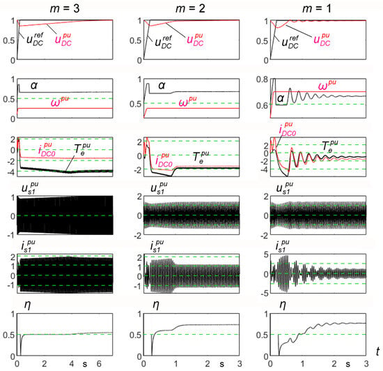
Figure 9.
Controlling the system with the 9-phase generator for selected constant values of m and ωpu: m = 3, ωpu = 0.25, m = 2, ωpu = 0.4, m = 1, ωpu = 0.7.
The waveform of efficiency η was calculated determining the instantaneous input power p1 and the output power p2:
The average powers P1 and P2 were determined as solutions of the differential equations,
Hence, the waveform of efficiency is
Figure 8b shows the enlarged voltage and current waveforms us1, us2, is1, is2 of two adjacent phases as well as the current waveform of and its average value in the time interval when m changes from 3 to 2. As can be seen, after changing m from 3 to 2, the current > 0 magnetizes MIM from the capacitor = 200 mF. The rms value of the stator phase current depends on the average load current of the LOAD circuit, , which corresponds to Figure 8b.
The large capacitance of means that a step change of m, with a relatively fast change in speed, does not significantly affect the voltage fluctuations . For this reason, the response of the system to the control signal was studied at a constant speed and a given sequence m. The results are shown in Figure 9. In the three considered cases, the voltage control is correct. However, the operation at m = 1 began at the minimum speed = 0.7, because at lower speeds the control system could not work properly. After reaching the steady state, the system had the lowest efficiency η = 0.6 for m = 3 and the comparable efficiencies η ≈ 0.8 for m = 2 and m = 1.
These cases are only single selected states of the generating system work. All steady-state operating points can be obtained after solving the generator equations using the equivalent circuit from Figure 4.
3.3. Steady State Characteristics Versus Speed of the Nine-Phase Generator
The steady state characteristics corresponding to the cases shown in Figure 9 are presented in Figure 10. These characteristics were calculated according to the scheme presented below.
- –
- The sequence is dependent on in the given speed ranges from to .
- –
- For the desired output voltage , , the control signal is . The load current for loading resistance and the rms phase current are, respectively,
- –
- The absolute slips (43, 45) are set to the value
- –
- For a given , the frequency has the value (45)
- –
- The input mechanical power is determined based on Equation (39) solution, and electromagnetic torque is calculated (41):
- –
- The output active electrical power and the passive power are described by equations
- –
- The power efficiency of the generator is given by (49).
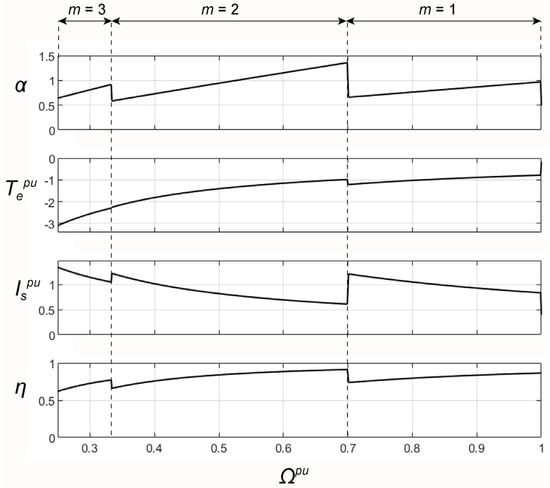
Figure 10.
Steady state characteristics of the 9-phase induction generator versus variable speed Ωpu.
Assuming = 0.25, = 1/3, = 1/3, = 0.7, = 0.7, = 1, the steady state characteristics are calculated. These characteristics shown in Figure 10 correspond to the transient operation presented in Figure 8a and Figure 9.
From the , , , characteristics shown in Figure 10, the same values were read as those obtained by the automatic control system reaching steady state in Figure 9 at a given for m = 3, 2, 1. The results allowing the comparison are shown in Table 2.
Comparing the results, the greatest differences are for m = 3 and . These differences were caused by several reasons listed below.
- –
- During simulation, MIM cooperates with PWM-controlled VSC, whereas the steady states are calculated at sinusoidal voltages, e.g., at m = 3, the 9-phase machine operates as a three-phase one with parallel connection of phase windings 1-4-7, 2-5-8, 3-6-9.
- –
- The MIM is controlled by the voltage controller RU which is an integral part of the whole system.
- –
- The absolute slip is determined using a linear approximation of the mechanical characteristic (45) to determine (52), while simulations are performed on the full mathematical model of MIM.
The generator can work with the maximum frequency when the desired voltage is not greater than the amplitude of phase voltage . Hence, . Then, provides sufficient reserve of PWM modulation depth. In the case shown in Figure 10 with m = 2, = 0.7, the system can operate at as at lower speeds.
Additionally, the presented method of steady state calculations was qualitatively and quantitively verified by comparison with measurements presented in [2] for vector control. This is presented in Figure 11. The steady state characteristics were calculated for currents and (50). The controlled voltage was = 100 V, = 45 V. The absolute slip was calculated using (51). The coefficient changes the load power because of stable controlling the average value of similarly as it was performed in [2] using the DC chopper. The PWM-controlled DC chopper was changing the current in the series connection of resistance = 8.5 Ω and inductance = 15 mH ( was necessary for proper operation of the chopper). The coefficient is then the depth of modulation and was regulated so as not to increase the phase current over the nominal value = 5.3 A, which gives = 11.2 A.

Figure 11.
Steady state characteristics of the 9-phase induction generator as a function of the driving speed Ωpu corresponding to the measurements; red dashed lines—data from measurement points taken from [2] (p. 16, Figure 7).
The differences between the calculations and measurements are caused by the fact that in calculations, the influence of VSC is not considered; additionally, there are power losses in the machine iron, mechanical, ventilation, and other power losses. In the circuit-oriented mathematical model, only power losses occur in the stator and rotor resistances. So, the real efficiency is lower than the calculated value. Nevertheless, it can be stated that the presented calculation method gives reliable results, since the winding loss dominates and the characteristics show proper trends of change.
3.4. Characteristics and Power Efficiency of the Twelve-Phase Induction Generator
The twelve-phase machine was based on the same stator and rotor as the nine-phase one. The stator winding scheme is presented in Figure 12.
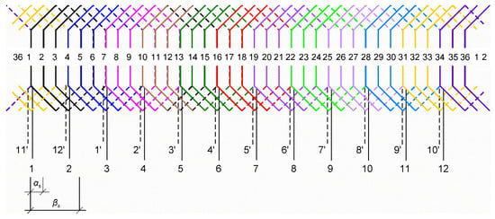
Figure 12.
Arrangement of the 12-phase winding with p = 1.
The mechanical characteristics were calculated for the in the range of 0 to 1.2 with the number of supply sequences and numbers = 1, 2, 3, 4, 5. They are presented in Figure 13 for the same constant supply voltage and the constant frequency . These characteristics have the no-load speeds resulting from (45): = 1, = 1/2, = 1/3, = 1/4, = 1/5. For each of these speeds, the stator per unit frequency is . Similarly, as for the nine-phase MIM (Figure 6), the steady state characteristics show the points of operation when the generator is driven with the power .
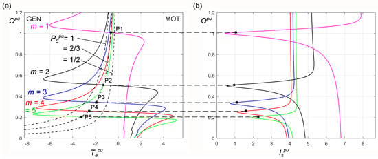
Figure 13.
Steady state characteristics of the 12-phase induction machine: (a) mechanical, (b) stator current; GEN—generator quadrant, MOT—motor quadrant.
For this machine, an analysis of the operation was performed with the speed varying from = 0.2 to = 1.0 and maintaining the output DC voltage at a constant level = 150 V for = 67.5 V. The results of calculations are presented in Figure 14a. The operation at the sequence number m = 5 was rejected because of a large magnetizing current.
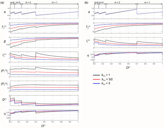
Figure 14.
The family of steady state characteristics of the 12-phase induction generator versus driving speed Ωpu for three values of Rd = kRd Rdo (Rdo = 5.88 Ω). (a) change from m = 2 to m = 1 at Ωpu = 0.5, (b) change from m = 2 to m = 1 at Ωpu = 0.7.
The control system maintains the output voltage at a given range of speed similarly to the nine-phase MIM. Efficiency drops slightly below 0.75 only for < 0.25 for m = 4. However, the operation of a scalar-controlled system with m = 1 and < 0.7 may be impossible, similarly to a nine-phase generator. Figure 14b shows the characteristics when switching m from 2 to 1 for speed = 0.7. This means that operation at m = 2 must be performed for the frequency increased to (for = 50 Hz, = 70 Hz). The output voltage is maintained at because .
With the vector control presented in [2] (Figure 3b), the generator can operate by switching the numbers m of the voltage sequence as shown in Figure 14a,b. With the scalar control, m should be switched as shown in Figure 14b because at < 0.7, controlling the voltage at m = 1 to the set value can be impossible. The higher efficiency at > 0.5 is obtained when controlling m according to Figure 14b.
The waveforms from Figure 14a correspond to the operating points P1, P2, P3, P4 on mechanical characteristics presented in Figure 13. The speeds are slightly greater than 1, ½, 1/3, ¼, respectively. These points correspond to the work at presented in Figure 14a by red lines. The values of from Figure 14a are almost the same as in Figure 13. E.g., for the point P3 in Figure 13, m = 3, ≈ 0.36, = 1, ≈ −1.8, ≈ 1.15. From Figure 14, m = 3, = 1/3, = 0.97, ≈ −2, ≈ 0.98. It is similar for other kRd values.
The efficiency of the full-scale power converter VSC is nonlinear and can be determined by measurement or proper simulation. For simplified considerations, this can be assumed as 95–99%. Typically, iron losses of an induction machine do not exceed 30% of the total losses. If the MIM efficiency is η1, taking into account only the copper losses ΔPCu, and the iron losses are , then the MIM efficiency will be lower ; e.g., η1 = 0.8, kFe = 0.3, η2 = 0.74. Similarly, the converter efficiency can be considered by entering the factor as a fraction of the copper losses, for example, = 0.05.
The comparison of the measurements and calculations presented in Figure 11 shows that the actual efficiency is lower than the calculated one. It can be clearly stated that the efficiency of a twelve-phase generator will be lower in practice than that resulting from Figure 14. Iron losses can be approximately calculated using the method presented in [19].
3.5. Reasons for Increasing Power Efficiency of a Multiphase Induction Generator
Following the considerations regarding SCIG’s efficiency presented in the Introduction, where , a formula for multiphase IG efficiency can be developed in a similar manner. Each mechanical characteristic of the multiphase generator has other slope coefficient for a given m (Table 1). These coefficients have a simplified mutual relationship . Thus, the generator efficiency is changing with respect to change in m determined by SEL (Figure 3a,b and Figure 7):
The above formula can be interpreted in the following way. If the speed decreases to = 0.5, the SEL changes m from m = 1 to m = 2. This means that the second term of (57) increases abruptly two times. So, the whole efficiency increases as shown in Figure 8a, Figure 10, Figure 11 and Figure 14. For the speed decreased to 1/3, the change in m is from 2 to 3, giving an effect similar to that before but at a lower degree of 3/2. The ratio of the efficiency increase depends on the third term of (57). Deriving specific formulae for is not necessary because the coefficients can be red directly from the mechanical characteristics presented in Figure 6 and Figure 13, which depend on all MIM parameters. It can be added that for higher-power MIMs, the coefficients are lower because the mechanical characteristics are more rigid.
4. Conclusions
- The variable speed range is from to , where for the nine-phase generator = 0.25, = 1, and for the twelve-phase generator = 0.2, = 1. Thus, the twelve-phase generator has a slightly larger useful speed change range.
- The entire generator speed range from to is divided into intervals … (Section 3.3), in which the generator is controlled at a different voltage sequence defined by parameter m. In these ranges, the generator operates with the number of pole pairs p · m.
- The efficiency η decreases with decreasing speed for a given m. However, increasing m at decreased speed causes efficiency increases according to (57).
- Increasing the number of phases beyond = 12 does not provide significant benefits in terms of increased efficiency or increased speed change range. For example, when , the number of sequences = 7 with respect to (6) and (36). Ignoring the control sequence for m = 7, we obtain only two additional control sequences for m = 5 and m = 6 that can be useful for very low speeds.
- The number of pole pairs should be p = 1. With p > 1, the core diameter must increase and the generator should be more expensive and heavier than for p = 1. Generators with M = 9 and M = 12 can be built using the stator core of a three-phase squirrel cage motor and its rotor. The nine-phase generator with a two-layer stator winding [1] (cg = 4, Table 1) has better properties than the one with the winding shown in Figure 5.
- The mathematical model in the form of differential equations and steady state equations can be used for induction machines with any number of phases (including M = 3).
- Multiphase systems are more robust than the three-phase systems because they can operate with broken phases (missing VSI leg, missing phase) and the generators can still produce the appropriate voltage even when vector controlled [3,4,32]. E.g., the measurement of a nine-phase generator operating with one phase broken was presented in [2] (p. 19, Figure 13), and one with two broken phases was analyzed in [10]. The effect of a step change in load is presented in [1,2] through laboratory measurements using scalar and vector control, respectively.
- The multiphase IG with the stator winding of type 2 (S = 2) [1] can operate only at the supply sequence m = 1 as the three-phase ones.
- This contribution focuses on the range of the uDC voltage regulation with the highest efficiency. This voltage can be used to control other AC loads powered by voltage inverters, e.g., the power grid in a WECS or electric motors in hybrid vehicles and electrical traction drives. In electric vehicles, the multiphase induction motor charges the DC voltage battery during regenerative brake. This allows for sufficiently high efficiency of braking energy recovery.
- The family of mechanical characteristics of a wind turbine may have maximum power points in a speed range = 0.2 … 0.5 of a twelve-phase generator for m = 4, 3, 2, which facilitates the implementation of MPPT [6,16,17] since these points are usually in the lower range of per unit speeds from 0.25 to 0.5. The specific design must consider the characteristics of the generator and turbine. Operating in this speed range can eliminate the need for a gear-box or reduce its gear ratio. A special eight-pole stator winding for a three-phase generator was proposed in [32]. This reduces the winding weight and dimensions. However, this number of poles is provided by the twelve-phase winding of Figure 12 when controlling the induction generator with sequence number m = 4. Other applications can concern the cooperation of small wind or hydro turbines driving the multiphase generator within photovoltaic farms supplying an energy storage system [27].
- For the control range in the speed range … , the average efficiency of the multiphase generator is comparable to the rated efficiency of a three-phase motor of the same power (it is a little smaller).
- Further research should aim towards practical application of the generators operating at any speed and allowing for constant DC voltage. It seems that the obvious is cooperation with wind and hydro turbines. However, the work on electric cars demands additional efforts to determine proper control. This is not the subject of this paper.
Funding
This research received no external funding.
Data Availability Statement
Any data presented in the paper may be obtained by contacting the authors.
Conflicts of Interest
The authors declare no conflict of interest.
Glossary
| List of More Important Symbols | |
| ; ; | matrix or vector; voltage vector; current vector |
| DC link capacitance | |
| slop coefficient of mechanical characteristic linear approximation | |
| slop coefficient for sequence number m | |
| ; | stator leakage inductance; rotor leakage inductance for kth symmetrical component |
| magnetizing inductance for kth symmetrical component | |
| ; | number of stator phases; number of rotor cage meshes |
| supply sequence number | |
| pole pair number | |
| ; | driving power; driving torque |
| ; | input power; output power |
| power loss | |
| ; | iron loss; copper loss |
| ; | stator phase resistance; rotor resistance for kth symmetrical component |
| ; | relative slip; relative slip for sequence number m |
| electromagnetic torque | |
| ; ; | amplitude of stator phase voltage; DC link voltage; DC voltage of DCSYS |
| ; | stator variable; rotor variable |
| kth symmetrical component of x (x = i—current, x = u—voltage, x = ψ—flux) | |
| complex amplitude of kth symmetrical component of x | |
| ; | conjugate variable; conjugate matrix or vector |
| stator per unit angular frequency (substitute description of ) | |
| ; | stator winding angles |
| rotor per unit angular frequency or absolute slip (substitute description of ) | |
| absolute slip for sequence number m | |
| power efficiency | |
| ; | MMF harmonic orders |
| magnetic flux | |
| phase angle | |
| ; | instantaneous rotational speed; per unit instantaneous rotational speed |
| ; | stator angular frequency; stator per unit angular frequency |
| ; | rotor angular frequency; rotor per unit angular frequency substitute value for m |
References
- Drozdowski, P.; Cholewa, D. Voltage Control of Multiphase Cage Induction Generators at a Speed Varying over a Wide Range. Energies 2021, 14, 7080. [Google Scholar] [CrossRef]
- Cholewa, D.; Drozdowski, P. Field-Oriented Control of a Nine-Phase Cage Induction Generator with Large Speed Changes and Variable Load. Energies 2024, 17, 790. [Google Scholar] [CrossRef]
- Prieto, I.G.; Duran, M.J.; Garcia-Entrambasaguas, P.; Bermude, M. Field-Oriented Control of Multiphase Drives with Passive Fault Tolerance. IEEE Tran. Ind. Electron. 2020, 67, 7228–7238. [Google Scholar] [CrossRef]
- Pantea, A.; Yazidi, A.; Betin, F.; Carrière, S.; Sivert, A.; Vacossin, B.; Henao, H.; Capolino, G.-A. Fault-tolerant Control of a Low-Speed Six-Phase Induction Generator for Wind Turbine. IEEE Trans. Ind. Appl. 2019, 55, 426–436. [Google Scholar] [CrossRef]
- Nounou, K.; Marouani, K. Control of a Dual Star Induction Generator Driven Wind Turbine. In Proceedings of the 2016 19th International Symposium on Electrical Apparatus and Technologies (SIELA), Bourgas, Bulgaria, 29 May–1 June 2016; IEEE: Piscataway, NJ, USA, 2016. [Google Scholar]
- Kali, Y.; Saad, M.; Rodas, J.; Mougharbel, I.; Benjelloun, K. Robust Control of a 6-Phase Induction Generator for Variable Speed Wind Energy Conversion System. In Proceedings of the 2020 5th International Conference on Renewable Energies for Developing Countries (REDEC), Marrakech, Morocco, 29–30 June 2020. [Google Scholar]
- Liu, H.; Bu, F.; Xu, H.; Huang, H.; Degano, M.; Gerada, C. Control-Winding Direct Power Control Strategy for Five-Phase Dual-Stator Winding Induction Generator DC Generating System. IEEE Trans. Transp. Electrif. 2020, 6, 73–82. [Google Scholar] [CrossRef]
- Xu, H.; Huang, W.; Bu, F.; Liu, H.; Lin, X. Harmonic Voltage Control for Five-Phase Induction Generator System with Direct Torque Control. In Proceedings of the 2017 20th International Conference on Electrical Machines and Systems (ICEMS), Sydney, NSW, Australia, 11–14 August 2017; IEEE: Piscataway, NJ, USA, 2017. [Google Scholar]
- Bu, F.; Hu, Y.; Huang, W.; Zhuang, S.; Shi, K. Wide-Speed-Range Operation Dual Stator-Winding Induction Generator DC Generating System for Wind Power Applications. IEEE Trans. Power Electron. 2015, 30, 561–573. [Google Scholar] [CrossRef]
- Maeko, M.G.; Muteba, M. Performance Analysis of a Nine-Phase Squirrel Cage Induction Motor under Faulty Conditions. Eng. Proc. 2024, 60, 14. [Google Scholar] [CrossRef]
- Bouyahia, O.; Yazidi, A.; Betin, F. Experimental Comparison of Robust Control Algorithms for Torque Ripple Reduction in Multiphase Induction Generators. Energies 2023, 16, 6702. [Google Scholar] [CrossRef]
- Hawkins, N.; Bhagwat, B.; McIntyre, M.L. Nonlinear Current-Mode Control of SCIG Wind Turbines. Energies 2021, 14, 954. [Google Scholar] [CrossRef]
- Abdelwanis, M.I. Optimizing the performance of six-phase induction motor powered electric vehicles with fuzzy-PID and DTC. Neural Comput. Appl. 2025, 37, 9721–9734. [Google Scholar] [CrossRef]
- Yaramasu, V.; Wu, B.; Sen, P.C.; Kouro, S.; Narimani, M. High-Power Wind Energy Conversion Systems: State-of-the-Art and Emerging Technologies. Proc. IEEE 2015, 103, 740–788. [Google Scholar] [CrossRef]
- Chinmaya, K.A.; Singh, G.K. Modeling and experimental analysis of grid-connected six-phase induction generator for variable speed wind energy conversion system. Electr. Power Syst. Res. 2019, 166, 151–162. [Google Scholar] [CrossRef]
- Mesemanolis, A.; Mademlis, C.; Kioskeridis, I. High-Efficiency Control for a Wind Energy Conversion System with Induction Generator. IEEE Trans. Energy Convers. 2012, 27, 958–967. [Google Scholar] [CrossRef]
- Fernandes Neto, C.d.O.; Sales Barros, L. Maximum Power Point Tracking of Squirrel-Cage Induction Generator-Based Wind Energy Conversion Systems. In Proceedings of the 2020 IEEE Power & Energy Society General Meeting (PESGM), Montreal, QC, Canada, 2–6 August 2020; IEEE: Piscataway, NJ, USA, 2020. [Google Scholar]
- Lee, D.-C.; Abo-Khalil, A.G. Optimal Efficiency Control of Induction Generators in Wind Energy Conversion Systems using Support Vector Regression. J. Power Electron. 2008, 8, 345–353. [Google Scholar]
- Abo-Khalil, A.G. Model-Based Optimal Efficiency Control of Induction Generators for Wind Power Systems. In Proceedings of the 2011 IEEE International Conference on Industrial Technology, Auburn, AL, USA, 14–16 March 2011; IEEE: Piscataway, NJ, USA, 2011. [Google Scholar]
- Boldea, I. Variable Speed Generators (Electric Power Engineering Series); CRC, Taylor & Francis Group: Boca Raton, FL, USA, 2005; ISBN/ASIN: 0849357152. [Google Scholar]
- Karakasis, N.; Tsioumas, E.; Jabbour, N.; Bazzi, A.M.; Mademlis, C. Optimal Efficiency Control in a Wind System with Doubly Fed Induction Generator. IEEE Trans. Power Electron. 2019, 34, 356–368. [Google Scholar] [CrossRef]
- Tapia, A.; Tapia, G.; Ostolaza, J.X.; Sáenz, J.R. Modeling and control of a wind turbine driven doubly fed induction generator. IEEE Trans. Energy Convers. 2003, 18, 194–204. [Google Scholar] [CrossRef]
- Ramos, T.; Medeiros Júnior, M.F.; Pinheiro, R.; Medeiros, A. Slip Control of a Squirrel Cage Induction Generator Driven by an Electromagnetic Frequency Regulator to Achieve the Maximum Power Point Tracking. Energies 2019, 12, 2100. [Google Scholar] [CrossRef]
- Huang, R.; Li, H.; Fei, F.; Qi, Y.; Song, T.; Zheng, S. Research on a New Control Method of Squirrel Cage Induction Generator for Wind Turbine. In Proceedings of the 2023 3rd International Conference on New Energy and Power Engineering (ICNEPE), Huzhou, China, 24–26 November 2023. [Google Scholar]
- Jakubowski, B.; Pieńkowski, K. Analysis and synthesis of converter control system of autonomous induction generator with field oriented control. Arch. Electr. Eng. 2013, 62, 267–279. [Google Scholar] [CrossRef]
- Levi, E. Advances in Converter Control and Innovative Exploitation of Additional Degrees of Freedom for Multiphase Machines. IEEE Trans. Ind. Electron. 2016, 63, 433–448. [Google Scholar] [CrossRef]
- Sadeq, A.M. Energy Storage Systems: A Comprehensive Guide, 1st ed.; Qatar Naval Academy: Khasooma, Qatar, 2023; ISBN 979-8-9907836-5-2. [Google Scholar] [CrossRef]
- Drozdowski, P.; Cholewa, D. Frequency Control of a 9-Phase Induction Motor at Switched Supply Sequence. In Proceedings of the 2018 International Symposium on Electrical Machines (SME), Andrychów, Poland, 10–13 June 2018; Available online: https://ieeexplore.ieee.org/document/8442620/ (accessed on 26 July 2025).
- Gontijo, G.; Krejci, D.; Guedes, S.; Tricarico, T.; Franc, B.; Aredes, M. Implementation of a Wind Turbine Emulator Test Bench Using a Squirrel Cage Induction Machine. In Proceedings of the 2017 Brazilian Power Electronics Conference (COBEP), Juiz de Fora, Brazil, 19–22 November 2017; IEEE: Piscataway, NJ, USA, 2017. [Google Scholar]
- Cholewa, D.; Drozdowski, P. Simulink Modeling of Multiphase Induction Motors. In Proceedings of the 2018 14th Selected Issues of Electrical Engineering and Electronics (WZEE), Szczecin, Poland, 19–21 November 2018; Available online: https://ieeexplore.ieee.org/document/8749007 (accessed on 26 July 2025).
- Drozdowski, P.; Cholewa, D. Natural Fault Tolerance of a Nine-Phase Induction Motor Drive Operating at Variable Frequency and Switched Supply Sequence. In Proceedings of the 2019 15th Selected Issues of Electrical Engineering and Electronics (WZEE), Zakopane, Poland, 8–10 December 2019; Available online: https://ieeexplore.ieee.org/xpl/conhome/8970388/proceeding (accessed on 26 July 2025).
- Grachev, P.Y.; Tabachinskiy, A.S.; Kanagavel, P. New Stator Construction and Simulation of High-Efficiency Wind Turbine Generators. IEEE Trans. Ind. Appl. 2020, 56, 1389–1396. Available online: https://ieeexplore.ieee.org/document/8950374 (accessed on 26 July 2025). [CrossRef]
Disclaimer/Publisher’s Note: The statements, opinions and data contained in all publications are solely those of the individual author(s) and contributor(s) and not of MDPI and/or the editor(s). MDPI and/or the editor(s) disclaim responsibility for any injury to people or property resulting from any ideas, methods, instructions or products referred to in the content. |
© 2025 by the author. Licensee MDPI, Basel, Switzerland. This article is an open access article distributed under the terms and conditions of the Creative Commons Attribution (CC BY) license (https://creativecommons.org/licenses/by/4.0/).