Abstract
This study presents a topology optimization approach to enhance the discharging performance of a latent heat thermal energy storage (LHTES) system using paraffin wax as the phase-change material (PCM) and a high-conductivity aluminium structure. Solidification is primarily governed by conduction, and the average heat transfer rate during this process is significantly lower than during melting; therefore, the optimization focused on the discharge phase. In a previous study, a novel LHTES device based on a Cartesian lattice was investigated experimentally and numerically. The validated numerical model from that study was adopted as the reference and used in a 2D topology optimization study based on the Solid Isotropic Material with Penalization (SIMP) method. The objective was to promote more uniform temperature distribution and reduce discharging time while maintaining the same aluminium volume fraction as in the reference device. Topology optimization produced a branched fin design, which was then extruded into a 3D model for comparison with the reference geometry. The optimized design resulted in improved temperature uniformity and a faster solidification process. Specifically, the time required to solidify 90% of the PCM was reduced by 12.3%, while the time to release 90% of the latent heat during the solidification process improved by 7.6%.
1. Introduction
The ever-increasing global demand for energy, coupled with the harmful environmental impacts of conventional fossil fuels, underscores the critical importance of developing and deploying renewable energy technologies. However, such technologies suffer from intermittency, making them less reliable. For instance, while solar is the most abundant source of renewable energy [1], its availability is disrupted during nighttime or overcast periods. Therefore, many studies focus on improving the dispatchability of renewables, highlighting the importance of energy storage systems. Energy storage systems can be broadly classified into five main categories: thermal, electrical, chemical, electrochemical, and mechanical energy storage [2]. As heat lies at the core of the global energy chain, accounting for approximately 90% of all energy conversion, transfer, and storage processes, thermal energy storage (TES) plays a pivotal role [3]. By bridging the gap between heat supply and demand, TES enables more efficient and reliable management of thermal energy, making it a critical component among energy storage technologies. TES systems are applicable in a wide range of operations, including electricity generation, industrial process heating, space heating in buildings, and hot water production [4]. They are also integrated into Carnot batteries, where excess electricity is converted into heat, stored in a TES unit, and later converted back into electricity when needed [5]. TES systems are generally classified into three main types based on the storage mechanism: sensible heat storage, latent heat storage, and thermochemical heat storage [6]. Sensible Heat Storage (SHS) is the most cost effective [7] and mature thermal energy storage method, relying on heating or cooling a storage medium, such as water, sand, or rocks, to store energy. The amount of energy stored or released depends on the specific heat capacity of the medium, the temperature change during charging or discharging, and the mass of the material used [8]. Based on scientific literature, the studies on SHS are mostly focused on space heating [9,10,11], industrial waste heat recovery [12,13,14], industrial process heat [15,16], and solar energy [17,18,19]. Although SHS is a mature and well-developed technology [20], it still has some drawbacks. Since higher storage temperatures are required to increase the energy density, these systems suffer from self-discharge losses. Additionally, due to their low energy density, they typically require large volumes for effective storage [6,7]. Compared to SHS, Latent Heat Thermal Energy Storage (LHTES) offers several advantages, including higher energy density, which enables more compact storage systems for specific applications. Additionally, LHTES systems are capable of releasing energy at a nearly constant temperature, which enhances their suitability for temperature-sensitive applications [20]. Also, LHTES systems can store heat at lower temperatures, which results in lower values of heat loss [21]. Despite these benefits, LHTES systems are mostly in the research and development phase [7], highlighting a growing need for further investigation and offering promising opportunities for future research and innovation in this field. Phase-change materials (PCMs) utilized in LHTES systems are categorized into organic, inorganic, and eutectic materials [8]. Among these, organic materials such as paraffins are commonly used for applications involving medium temperature ranges [22]. Organic PCMs offer advantages including low supercooling, non-corrosiveness, stability under varying operating conditions, and cost-effectiveness [23,24]. However, one of the primary limitations of PCMs, particularly organic ones, is their low thermal conductivity, which results in extended charging and discharging times (i.e., low specific power) [22,25]. To address this, numerous studies have investigated the addition of highly conductive nanoparticles to PCMs to enhance their effective thermal conductivity. Şahan et al. [26] investigated paraffin–nanomagnetite (Fe3O4) composites at two different mass fractions—10% and 20%. Their results showed that the thermal conductivity increased by 48% and 60% for the 10% and 20% mass fractions, respectively. Bahiraei et al. [27] developed three paraffin-based nanocomposites incorporating carbon nanofiber, graphene nanoplatelets, and graphite nanopowder, with the mass fractions ranging from 2.5% to 10%. Their combined experimental and numerical investigations revealed that while the addition of nanoparticles significantly enhances the thermal conductivity of the composite, it also adversely affects natural convection during the melting process. As a result, a trade-off emerges between improved thermal conductivity and the suppression of natural convection induced by the nanoparticles. However, repeated melting and solidification cycles may disrupt the uniform dispersion of nanoparticles. Moreover, nanoparticles are susceptible to agglomeration and sedimentation, which can degrade the thermal performance of the composite over time [28]. Another popular method to enhance the effective thermal conductivity of LHTES systems is the integration of metal matrices and porous structures. In this context, Morciano et al. [22] developed a prototype LHTES device based on a 3D Cartesian metal lattice fabricated via additive manufacturing. The design was specifically aimed at reducing charging and discharging times. Their novel system achieved impressive specific power values of and for charging and discharging processes, respectively. Ribezzo et al. [29] conducted an experimental investigation on a shell-and-tube LHTES prototype filled with copper wool. They explored the effects of different fibre thicknesses and fibre placement around the LHTES tubes. Their results demonstrated up to a 16% reduction in melting time and a significant enhancement in mean power output—by 53% during charging and 205% during discharging. Ahmed et al. [30] experimentally investigated the performance of paraffin/copper foam and paraffin/iron–nickel foam composites. Both composites enhanced the thermal performance of paraffin, with the paraffin/copper composite exhibiting a more uniform temperature distribution and approximately 21% shorter charging time compared to the paraffin/copper composite. However, metal foams have some drawbacks: fully filling all pores with a PCM is challenging, and some pores may remain empty, acting as thermal insulators. Despite this, these structures restrict and suppress convective heat transfer [31]. Another method to enhance the thermal performance of PCMs is encapsulation. Encapsulated PCMs are categorized by particle size into macro, micro, and nano scales. The size of the capsules significantly affects thermal behaviour, with smaller capsules providing a higher surface-area-to-volume ratio, thereby improving heat transfer efficiency [32]. Despite offering a higher surface-area-to-volume ratio, PCM microencapsulation involves complex and costly manufacturing processes [33]. Rezaeishaker et al. [34] numerically investigated a novel fountain-shaped macro-capsule for latent heat storage. The proposed design outperformed conventional enclosures, reducing charging time by up to 43% compared to the previously optimized pear-shaped model. Another approach widely employed in the literature to address the low thermal conductivity of PCMs is the incorporation of fins. Fins are commonly adopted, as they do not cause long-term degradation of the PCM or raise safety issues. Consequently, the design and optimization of heat conduction channels incorporating fin structures have received considerable attention [35]. Zaib et al. [36] conducted a numerical study to examine the influence of various parameters—such as the number, length, and thickness of fins—on the total phase-change duration. Their optimized configuration resulted in a 92% reduction in melting time. Using a two-dimensional model, Zhang et al. [37] studied the effects of different fin lengths and tilt angles on the melting behaviour of PCMs. The heat transfer performance of fins depends heavily on their size, distribution, and geometry, making their design a complex process. Due to the many interrelated variables, fins have been extensively investigated [38]. However, literature on finned structures is often characterized by complex physics and limited design freedom, making it difficult to derive clear, fundamental design guidelines [39]. Topology optimization is a computational design approach that generates structural layouts optimized for performance based on specified design constraints. Unlike traditional methods, it is not limited by the initial topology, allowing for superior performance compared to manually designed layouts based on engineering intuition and experience [40]. Topology optimization was initially introduced in structural mechanics to address configuration problems, with the pioneering work of Bendsøe and Kikuchi [41] laying the foundation. With the advancement of Additive Manufacturing, which has made it feasible to produce the non-intuitive designs generated by topology optimization, this approach has gained increasing popularity within the heat transfer community. This method was widely utilized in heat sinks [42,43,44] and it is gaining popularity in the case of LHTES systems. Using a density-based approach, Pizzolato et al. [39] performed topology optimization on a cylindrical LHTES system to maximize performance across three different objective functions. Their results uncovered design features and trends that alternative design methods would hardly reveal. In a subsequent study, Pizzolato et al. [45] incorporated the natural convection effects of the liquid PCM into both the design and performance evaluation of a topology-optimized LHTES unit. They found that designs optimized for melting and those optimized for solidification exhibited distinct characteristics. Ait Laasri et al. [46] performed topology optimization on a cylindrical LHTES unit by considering two separate fin configurations—one with radial fin development and one with axial. They found that the radial fin layout outperformed the axial case, reducing discharge time by up to 86.3% compared to a finless shell and tube configuration. Zhang et al. [35] investigated a shell and tube LHTES system using topology optimization and identified an optimal fin volume ratio of 20%, balancing heat transfer performance and storage capacity. In a subsequent experimental study, they showed that, compared to conventional longitudinal fins, the topology-optimized fins reduced PCM charge and discharge durations by 46.8% and 47.1%, respectively. Zhang et al. [47] examined how various optimization parameters influence the design and performance of fins in a shell and tube LHTES system. Their work suggests a theoretical foundation for applying topology optimization to fin distribution within such systems. He et al. [38] applied topology optimization to a cylindrical LHTES unit and then experimentally compared three configurations: optimized fins, conventional fins, and no fins. Their optimized design delivered approximately 68% and 25% higher heat transfer efficiency compared to the finless and the conventional-fin configurations, respectively. The literature review demonstrates that topology optimization can substantially reduce charging and discharging times, highlighting its effectiveness. In this work, we applied topology optimization to a high-performance cubic LHTES unit previously manufactured and tested by Morciano et al. [22], which already featured a novel design resulting in reduced charging and discharging times.
2. Materials and Methods
2.1. Physical Model
In a recent study, an LHTES mock-up was developed and fabricated using laser powder bed fusion (L-PBF) from AlSi10Mg aluminium alloy powder and subsequently infiltrated with paraffin wax (RT70HC, Rubitherm) (see ref. [22]). The high thermal conductivity of the metal lattice was leveraged to homogenize the temperature distribution within the PCM and simultaneously reduce its melting and solidification times. The lattice was also designed to function as a heat exchanger between the heat transfer fluid (HTF) and the LHTES system. The metal structure had a cubic form (80 mm × 80 mm × 80 mm) and featured an internal 3D Cartesian lattice composed of repeated hollow cubic elements with 6 mm sides (Figure 1a). HTF flowed through an inner duct (34 mm inner, 46 mm outer side) and across external fins (3 mm thick, 9 mm long) integrated into the device. The device was enclosed in a wooden casing to guide the HTF over the external fins. To enhance thermal insulation from the environment, the prototype was covered with a layer of mineral wool (see Figure 1). The aluminium structure had the mass of approximately 630 g.
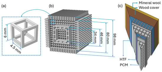
Figure 1.
Design of the LHTES mock-up (from Morciano et al. [22]): (a) Unit cell of the Cartesian lattice, (b) 3D CAD model of the device, and (c) 3D computational model illustrating the simulation domains. To reduce computational cost, geometric symmetries were exploited, and only one-eighth of the device was simulated.
This optimization study mainly focused on solidification, as the average heat transfer rate during this process is significantly lower than during melting [48]. Therefore, the primary objective is to design optimized fins that promote a more uniform temperature distribution and, consequently, faster discharging time. In this paper, the validated numerical model developed in the previous study (ref. [22]) was adapted for the topology optimization analysis. For the sake of simplicity and to avoid loss of generality, convective heat losses, as well as the wooden cover and mineral wool insulation, were neglected. In LHTES systems, solidification is predominantly governed by heat conduction [39]; therefore, neglecting convection inside the PCM is a reasonable assumption, as demonstrated in ref. [22]. A purely conductive heat transfer model was considered; hence, the HTF flow was not simulated. Instead, a Dirichlet boundary condition was applied to the surfaces of the flow channels. During the discharge process, the temperature of the flow channels was assumed to be C, while the initial temperature of the LHTES was set to C. Conversely, during the charging process, C and C. To ensure a credible comparison, the same simplifying assumptions and boundary conditions were applied to the reference model proposed by Morciano et al. [22] (see Figure 2e). The boundaries assigned with are highlighted in blue in Figure 2d,e.
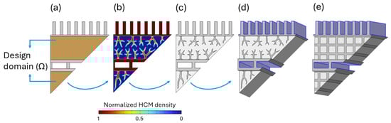
Figure 2.
Evolution of the topology optimization design: (a) Initial guess of the design, (b) Output material volume factor (), (c) Final 2D geometry, and (d) Extruded 3D geometry including simulation domains. The simplified reference geometry is shown in (e). To reduce computational cost, geometric symmetries were exploited, and only one-eighth of the device was simulated.
The topology optimization process begins with an initial 2D design guess (Figure 2a), onto which the boundary conditions are imposed. The resulting optimized fin geometry is then extruded to construct the 3D model to evaluate the LHTES device (Figure 2d). The topology-optimized fins were designed with a volume fraction constraint to ensure that the final structure contained the same volume of highly conductive material (HCM) and PCM as the original design.
2.2. Topology Optimization Approach
Topology optimization is a design method used to determine the optimal material layout within a given structure to enhance its performance, while satisfying specified constraints. In line with scientific literature, density-based methods, specifically the Solid Isotropic Material with Penalization (SIMP), are the most widely used techniques. In this approach, a hypothetical porous material characterized by a normalized density is introduced to enable a continuous transition between multiple phases. This normalized density serves as an optimization variable and is used to interpolate the material properties. The interpolation scheme is designed to penalize intermediate density values, thereby promoting convergence towards designs with clearly separated phases [39]. In other words, the method biases the elements towards solid (1) or void (0) material properties.
Numerical instabilities in density-based topology optimization typically fall into two main categories: checkerboarding and mesh dependency. These challenges can be mitigated using filtering techniques, which not only reduce such instabilities but also help enforce a minimum feature size constraint in the design. In this study, a Helmholtz filter was utilized [49]:
where is the filtered material volume factor and is the filter radius or the minimum length scale. The control material volume factor, , represents an artificial density that is forced to its bounds by the SIMP method. It ranges from , representing void regions filled with the PCM, to , corresponding to solid regions composed of the HCM. By smoothing the gradients of the design variable field, the filtering process adds a degree of fuzziness, or grey areas, to the material distribution. Although this can simplify the optimization problem to solve, it may result in designs that depend on regions with non-physical properties due to intermediate material values. Therefore, to achieve sharp boundaries, density-based topology optimization approaches rely on projection schemes. In this study, a hyperbolic tangent-based projection was applied:
where represents the projected material volume factor, which is bounded between 0 and 1, while and denote the projection threshold and the steepness of the projection function, respectively.
Intermediate values of the design variable lack a clear physical meaning; therefore, if such values appear in the optimal design, the optimization problem must be adjusted accordingly. In the context of volume constraints or objectives, this adjustment is commonly implemented through penalization. To interpolate the thermophysical properties, SIMP interpolation was utilized:
where p is the material penalization exponent.
The topology optimization in this study was carried out using the COMSOL Multiphysics (version 6.3) Optimization Module. Due to the large number of control variables, a gradient-based optimization algorithm, the Globally Convergent Method of Moving Asymptotes (GCMMA), was employed. Gradient-based methods require the sensitivity (the derivative) of the objective function with respect to the control variables to update the set of design variables. The adjoint method is particularly well-suited for such cases, offering an efficient means of computing sensitivities when dealing with a high number of control variables.
The optimization parameters used in this study were obtained through a continuation scheme and are consistent with values reported in the literature (see ref. [47]). The values used are material penalization exponent , projection steepness , projection threshold , and filter radius mm.
2.3. Objective Function and Constraints
According to the target of the study, the topology optimization problem reads as follows:
where is the average temperature in the design domain, R is the residual of the discretized governing equations, and is the volume fraction of the HCM in the reference LHTES prototype. The design domain is highlighted in Figure 2a. Clearly, the volume constraint is also important to prevent the trivial solution of completely filling the design domain () with the HCM.
2.4. Finite Elements Model
The conductive heat transfer in the LHTES device is computed in three dimensions using the finite element software COMSOL Multiphysics (version 6.3). To reduce computational cost, geometric symmetries of the system are exploited, allowing the simulation of only one-eighth of the full device (see Figure 2d,e). This optimization study mainly focuses on solidification, as the average heat transfer rate during this phase is significantly lower than during melting. In LHTES systems, the solidification process is primarily governed by heat conduction [39]. The energy equation was solved for aluminium and PCM domains:
where is the density, is the specific heat capacity, k is the thermal conductivity, and T is the temperature. The phase-change of paraffin wax RT70HC was modelled using the apparent specific heat capacity method, where the latent heat is incorporated as a temperature-dependent enhancement of the specific heat. This approach introduces peaks at the phase-change temperatures (C and C), modelled using Gaussian functions whose integrals match the total latent heat. The apparent specific heat was fitted to experimental data from the PCM manufacturer (see ref. [22]):
where , , , , and are material-dependent parameters obtained from the best fit of the experimental data. The characteristic phase-change temperatures are C (340.15 K) and C (343.15 K). G is a Gaussian function of T, centred in , with a standard deviation of . It should be emphasised that , the specific heat of the PCM, is the assumed constant for both the solid and liquid phases. The fitting curves and their parameters are shown in Figure 3 and Table 1, respectively. Additionally, the density transition from solid () to liquid () was modelled using a smooth step function centred around the phase-change temperature, ensuring a continuous variation across the transition range. The thermal conductivity of paraffin wax was considered . The thermophysical properties of the aluminium alloy AlSi10Mg were considered constant throughout this study, with , , and .
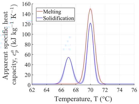
Figure 3.
Apparent specific heat capacity of the investigated PCM, with shaded regions indicating the uncertainty in the fitted curves based on the data provided in Table 1. The figure is adapted from ref. [22].

Table 1.
Material-dependent coefficients of Equation (8) for the apparent specific heat capacity () of paraffin RT70HC during the fusion and solidification processes. The table is adapted from ref. [22].
The liquid volume fraction of the PCM is described using a piecewise function that depends on the phase-change temperature and the temperature interval of the transition zone ():
The thermal performance of the device was evaluated by analysing the energy dynamics during the charging and discharging processes, specifically focusing on the total thermal energy (E) and the latent heat component (L). The total energy represents the combined sensible and latent heat stored or released within the PCM and the aluminium domains, while the latent heat reflects the energy associated solely with the phase-change of the PCM. The total thermal energy was obtained from
where denotes the initial temperature at the beginning of the charging or discharging process. In a similar manner, the latent heat L stored or released by the PCM during the phase-change was calculated as follows:
A grid sensitivity analysis is presented in Appendix A to verify that the results are independent of the mesh resolution.
3. Results
The evolution of the optimized geometry is shown in Figure 2a–c. The fins exhibit a branched structure extending through the PCM domain, promoting a more uniform temperature distribution.
Simplified models of both the reference and topology-optimized LHTES systems were evaluated under identical thermal conditions. Figure 4a,b show the released and stored energy for the simplified reference model and the topology-optimized model, respectively. At intermediate stages of both the charging and discharging processes, the optimized model exhibits superior performance, with greater absorption and release of both total and latent energy. A key parameter that characterizes the performance of the device is the time required to store or release 90% of the available latent heat, referred to as . Lower values indicate a faster thermal response of the LHTES unit. Compared to the reference model, the optimized device demonstrated improvements of 5.6% and 7.6% in for the charging and discharging processes, respectively. Another interesting observation is presented in Figure 4c, which highlights a significant improvement in PCM solidification during the discharging process. In the optimized storage device, 90% of the PCM solidifies in 30.6 s, compared to 34.9 s in the reference case, indicating a 12.3% improvement. However, during the charging process (Figure 4d), the improvement in the melted fraction of the PCM is slightly lower, at 9.4%. For better visualization, Figure 5 summarizes the values and also the time required for 90% of the PCM to melt or solidify during the charging and discharging processes.
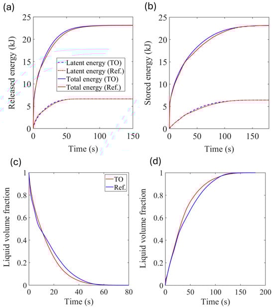
Figure 4.
Performance comparison between the simplified reference model and the topology-optimized (TO) model: (a) Thermal energy released, (b) Thermal energy stored and liquid volume fraction of the PCM during (c) discharging and (d) charging.
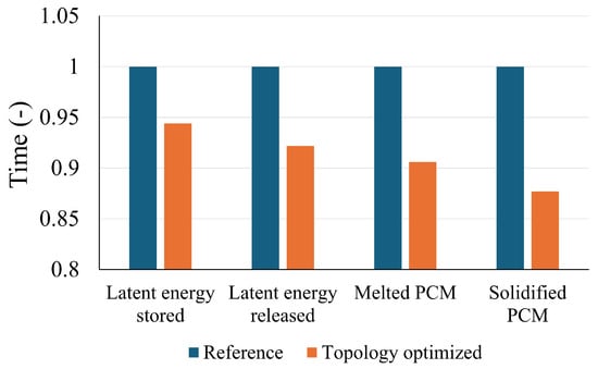
Figure 5.
Time to store or release 90% of the latent energy and achieve 90% melting or solidification of the PCM. The vertical axis is normalized by the corresponding value of the reference case.
Figure 6a,b present the liquid volume fraction distribution within the optimized LHTES unit at t = 15 s and t = 30 s, respectively. Each panel includes a cross-sectional view (left) and a 3D cutaway view (right), offering complementary perspectives on the solidification progress. Solidification begins at the locations next to the branches and gradually expands, eventually connecting the solid regions. At t = 30 s (Figure 6b), the PCM has undergone near-complete solidification (99%). Only a few narrow, dispersed channels of liquid PCM persist, mostly in regions where heat removal is least efficient. This demonstrates the effectiveness of the optimized geometry in promoting rapid and spatially uniform solidification by enhancing thermal pathways and minimizing residual liquid zones.
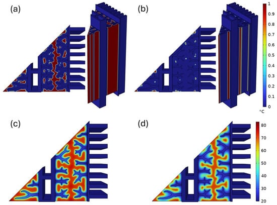
Figure 6.
Liquid volume fraction of the PCM during solidification at (a) t = 15 s and (b) t = 30 s; Temperature maps during solidification at (c) t = 15 s and (d) t = 30 s.
Figure 6c,d illustrate the temperature distribution within the optimized LHTES device at t = 15 s and t = 30 s, respectively. At t = 15 s (Figure 6c), the temperature gradients indicate that heat is being effectively conducted away from the LHTES device, initiating solidification in regions near the branches. By t = 30 s (Figure 6d), the extent of high-temperature zones has significantly diminished, particularly near the branches. However, isolated pockets of elevated temperature persist, primarily in regions farther from the branches, indicating the presence of residual liquid PCM, more clearly visible in Figure 6b. These localized hotspots are the result of slower cooling and delayed phase-change in thermally isolated zones. Quantitatively, temperature deviations of up to C were recorded between the hotspot regions and the volume-averaged PCM temperature at t = 30 s.
The total energy (E) and latent energy (L) absorbed and released during the charging and discharging processes, as calculated from Equations (10) and (11), are presented in Figure 7. Nearly 30% of the total energy stored and released by the system is attributed to latent heat, highlighting the significant role of phase-change materials in energy storage. In contrast, the sensible heat stored by the aluminium matrix accounts for 22% of the total energy. Furthermore, the large share of sensible heat stored within the PCM—approximately 50%—demonstrates that, even outside the phase-change region, the PCM plays a major role in the system’s thermal inertia. This distribution highlights the advantage of combining latent and sensible heat storage mechanisms, allowing the system to store substantial energy quantities without necessitating higher HTF temperatures. Increasing the HTF temperature would boost the sensible heat contribution, thereby increasing the overall energy stored. However, this would also lead to higher thermal losses during the storage period, potentially reducing the net energy efficiency of the system. Additionally, the nearly equal energy shares observed during charging and discharging confirm that the system operates in a balanced manner.
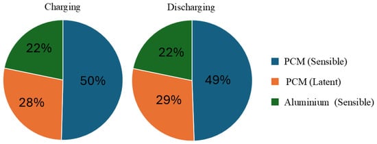
Figure 7.
Latent and sensible contributions during charging (left) and discharging (right) in the optimized device.
4. Discussion
As discussed in Section 3, a few hotspots were observed during the discharge process, particularly near regions of low aluminium connectivity and at greater distances from the heat transfer surface. Although achieving a uniform temperature distribution within the PCM was a primary objective, this goal was constrained by the imposed volume fraction of aluminium, which was limited to ensure a fair and consistent comparison with the reference device. This constraint, while necessary for benchmarking, inherently reduces the effective thermal conductivity of the structure and can lead to slower heat diffusion across the domain, contributing to the formation of localized hotspots. Such non-uniformities can impact both the rate and completeness of energy recovery. It is also important to note that increasing the aluminium volume fraction, while beneficial for enhancing thermal conductivity and mitigating hotspots, comes at the cost of increased overall device mass and a reduced PCM volume fraction. Since the latent heat storage capacity is directly linked to the amount of PCM, higher aluminium content inevitably results in lower total latent heat. This trade-off raises a key question regarding the net impact on the device’s total energy storage and release capacity, both sensible and latent, which warrants detailed investigation. Future studies could investigate the impact of varying the aluminium volume fraction on the thermal performance and energy density of the LHTES device. Performing a multi-objective optimization to map the Pareto front between discharge speed and latent heat capacity would provide a more comprehensive understanding of the optimal trade-offs for different application requirements.
It is important to note that the present optimization was carried out in a simplified 2D domain, and the resulting geometry was subsequently extruded to construct the three-dimensional model used for performance evaluation. While this approach significantly reduces computational effort and still captures key thermal and structural characteristics, it inherently limits the design freedom compared to a full 3D topology optimization. Performing the optimization directly in 3D would allow for a more realistic and potentially more efficient configuration; however, such an approach is considerably more computationally expensive, especially when coupled with transient heat transfer and phase-change modelling. Therefore, 3D topology optimization is left for future work, as computational resources become more accessible.
It is also imperative to consider long-term stability and durability. Although the present study focuses on the thermal performance of the LHTES device under a single charge–discharge cycle, structural integrity under repeated thermal cycling remains a critical factor for real-world applications. While Morciano et al. [22] reported stable performance during repeated charging and discharging cycles, factors such as thermal expansion, PCM degradation, and mechanical stresses induced by melting and solidification may affect long-term performance. Future work should incorporate thermo-mechanical simulations or accelerated thermal cycling tests to assess the durability and lifetime of the topology-optimized design. Such studies would help determine whether the branched fin structures can maintain their performance and integrity over extended operation.
Moreover, the current numerical model assumes ideal conditions, including negligible heat loss to the environment and a constant temperature on the surface of HTF channels, as in ref. [45]. In practice, factors such as imperfect PCM behaviour (e.g., subcooling, hysteresis), thermal contact resistance, and environmental heat losses could lead to deviations from the simulated performance. Due to the small scale of the device and the fluid dynamic conditions of the reference case (i.e., low HTF velocity), the assumption of negligible axial temperature gradients and a constant wall temperature is considered credible; however, future studies should aim to incorporate these effects or perform experimental validation to assess the practical robustness of the numerical model.
Additive manufacturing enables the fabrication of complex geometries, such as the topology-optimized structures proposed in this study. Therefore, in future work, a small-scale prototype could be produced and tested experimentally. This would help bridge the gap between the current simplified numerical model and actual operating conditions, providing valuable insights into the practical applicability and performance of the optimized design.
5. Conclusions
This study demonstrates the effectiveness of topology optimization in enhancing the thermal performance of LHTES devices. The optimized fin geometry, characterized by branched structures extending throughout the PCM domain, successfully promoted a more uniform temperature distribution and accelerates phase-change processes. Compared to the reference design, the topology-optimized system showed significant improvements in thermal response times, with reductions of 5.6% and 7.6% in the time required to store and release 90% of the latent heat, respectively. Notably, the optimized device exhibited significantly faster phase-change dynamics, achieving 90% PCM solidification 12.3% earlier during discharge, and 90% PCM melting 9.4% earlier during charge, compared to the reference case.
Detailed analysis of energy contributions revealed that latent heat accounts for nearly 30% of the total energy stored and released by the system, underscoring the crucial role of the PCM in thermal energy storage. The sensible heat stored in the aluminium matrix contributes about 22% of the total energy. Additionally, the PCM itself stores approximately 50% of the sensible heat outside its phase-change temperature range, highlighting its significant contribution to the system’s thermal inertia. This effective combination of latent and sensible heat storage mechanisms enhances the energy density and enables the system to store substantial amounts of energy at relatively lower HTF temperatures, thereby improving overall efficiency while minimizing thermal losses.
Overall, the topology-optimized LHTES design offers a promising approach to improve the thermal performance and efficiency of PCM-based energy storage systems, potentially enabling faster charge–discharge cycles and more effective thermal management in practical applications. Development of more efficient LHTES devices can greatly promote their utilization in real-world applications, including solar thermal energy storage and industrial heat management, by enabling faster thermal response, higher energy density, and more effective integration with renewable energy sources.
Author Contributions
Conceptualization, A.M. and M.M.; methodology, A.M.; software, A.M. and M.M.; validation, M.M.; formal analysis, A.M.; investigation, A.M.; resources, E.C.; data curation, A.M.; writing—original draft preparation, A.M.; writing—review and editing, A.M., M.M., P.A. and E.C.; visualization, A.M.; supervision, M.M., P.A. and E.C.; project administration, P.A. and E.C. All authors have read and agreed to the published version of the manuscript.
Funding
This research received no external funding.
Data Availability Statement
Data is contained within the article.
Conflicts of Interest
The authors declare that they have no known competing financial interests or personal relationships that could have appeared to influence the work reported in this paper.
Abbreviations
The following abbreviations are used in this manuscript:
| GCMMA | Globally convergent method of moving asymptotes |
| HTF | Heat transfer fluid |
| L-PBF | Laser powder bed fusion |
| PCM | Phase-change material |
| SHS | Sensible heat storage |
| SIMP | Solid isotropic material with penalization |
| TES | Thermal energy storage |
Appendix A
A grid independence study was conducted to verify that the spatial discretization did not significantly influence the results of the transient simulations performed in COMSOL Multiphysics. Given the time-dependent nature of the problem, it was essential to ensure that the predicted temporal evolution of the thermal field remained consistent across different mesh densities. Since the optimized fins featured a fine structure, small computational elements were required within the fins and in the surrounding PCM regions. Four computational meshes of increasing resolution—denoted as Mesh 1 (coarsest) through Mesh 4 (finest)—were tested. For all simulations, the same physics settings, boundary conditions, and solver configurations were used. An adaptive time-stepping algorithm was employed with a fixed relative tolerance, ensuring that the time discretization error remained controlled and consistent across all meshes. To assess the influence of mesh resolution, the temporal evolution of the liquid volume fraction of the PCM was tracked throughout the simulation. Comparisons were made at the specific time instant of t = 10 s. The results showed that the differences between Mesh 3 and Mesh 4 were minimal; therefore, Mesh 3 was selected for subsequent calculations. Details of the grid study are provided in Table A1 and Figure A1. A cross-sectional view of the selected computational grid is shown in Figure A2.
Table A1.
Details of the grid study.
Table A1.
Details of the grid study.
| Average Cell Size (m) | Number of Elements () | Liquid Volume Fraction of the PCM () | |
|---|---|---|---|
| Mesh 1 | 1.489 × 10⁻⁸ | 6.591 | 0.4953 |
| Mesh 2 | 1.117 × 10⁻⁸ | 4.071 | 0.4961 |
| Mesh 3 | 8.421 × 10⁻⁹ | 3.070 | 0.4967 |
| Mesh 4 | 5.202 × 10⁻⁹ | 2.302 | 0.4967 |

Figure A1.
Liquid volume fraction for different grids at t = 10 s.

Figure A2.
A view of the chosen computational grid.
References
- Kannan, N.; Vakeesan, D. Solar energy for future world: -A review. Renew. Sustain. Energy Rev. 2016, 62, 1092–1105. [Google Scholar] [CrossRef]
- Sayed, E.T.; Olabi, A.G.; Alami, A.H.; Radwan, A.; Mdallal, A.; Rezk, A.; Abdelkareem, M.A. Renewable energy and energy storage systems. Energies 2023, 16, 1415. [Google Scholar] [CrossRef]
- Sadeghi, G. Energy storage on demand: Thermal energy storage development, materials, design, and integration challenges. Energy Storage Mater. 2022, 46, 192–222. [Google Scholar] [CrossRef]
- Guney, M.S.; Tepe, Y. Classification and assessment of energy storage systems. Renew. Sustain. Energy Rev. 2017, 75, 1187–1197. [Google Scholar] [CrossRef]
- Dumont, O.; Frate, G.F.; Pillai, A.; Lecompte, S.; De paepe, M.; Lemort, V. Carnot battery technology: A state-of-the-art review. J. Energy Storage 2020, 32, 101756. [Google Scholar] [CrossRef]
- Mabrouk, R.; Naji, H.; Benim, A.C.; Dhahri, H. A state of the art review on sensible and latent heat thermal energy storage processes in porous media: Mesoscopic Simulation. Appl. Sci. 2022, 12, 6995. [Google Scholar] [CrossRef]
- Seyitini, L.; Belgasim, B.; Enweremadu, C.C. Solid state sensible heat storage technology for industrial applications—A review. J. Energy Storage 2023, 62, 106919. [Google Scholar] [CrossRef]
- Sarbu, I.; Sebarchievici, C. A comprehensive review of thermal energy storage. Sustainability 2018, 10, 191. [Google Scholar] [CrossRef]
- Kizilkan, O.; Dincer, I. Borehole thermal energy storage system for heating applications: Thermodynamic performance assessment. Energy Convers. Manag. 2015, 90, 53–61. [Google Scholar] [CrossRef]
- Aresti, L.; Christodoulides, P.; Panayiotou, G.P.; Florides, G. The potential of utilizing buildings’ foundations as thermal energy storage (TES) units from solar plate collectors. Energies 2020, 13, 2695. [Google Scholar] [CrossRef]
- Ali, E.; Ajbar, A.; Lamrani, B. Numerical Investigation of Thermal Energy Storage Systems for Collective Heating of Buildings. Buildings 2024, 14, 141. [Google Scholar] [CrossRef]
- Ortega-Fernández, I.; Rodríguez-Aseguinolaza, J. Thermal energy storage for waste heat recovery in the steelworks: The case study of the REslag project. Appl. Energy 2019, 237, 708–719. [Google Scholar] [CrossRef]
- König-Haagen, A.; Höhlein, S.; Brüggemann, D. Detailed exergetic analysis of a packed bed thermal energy storage unit in combination with an Organic Rankine Cycle. Appl. Therm. Eng. 2020, 165, 114583. [Google Scholar] [CrossRef]
- Kauko, H.; Rohde, D.; Knudsen, B.R.; Sund-Olsen, T. Potential of thermal energy storage for a district heating system utilizing industrial waste heat. Energies 2020, 13, 3923. [Google Scholar] [CrossRef]
- Zanganeh, G.; Pedretti, A.; Haselbacher, A.; Steinfeld, A. Design of packed bed thermal energy storage systems for high-temperature industrial process heat. Appl. Energy 2015, 137, 812–822. [Google Scholar] [CrossRef]
- Stack, D.C.; Curtis, D.; Forsberg, C. Performance of firebrick resistance-heated energy storage for industrial heat applications and round-trip electricity storage. Appl. Energy 2019, 242, 782–796. [Google Scholar] [CrossRef]
- El Alami, K.; Asbik, M.; Agalit, H. Identification of natural rocks as storage materials in thermal energy storage (TES) system of concentrated solar power (CSP) plants—A review. Sol. Energy Mater. Sol. Cells 2020, 217, 110599. [Google Scholar] [CrossRef]
- Salomoni, V.A.; Majorana, C.E.; Giannuzzi, G.M.; Miliozzi, A.; Di Maggio, R.; Girardi, F.; Mele, D.; Lucentini, M. Thermal storage of sensible heat using concrete modules in solar power plants. Sol. Energy 2014, 103, 303–315. [Google Scholar] [CrossRef]
- Herrmann, U.; Kelly, B.; Price, H. Two-tank molten salt storage for parabolic trough solar power plants. Energy 2004, 29, 883–893. [Google Scholar] [CrossRef]
- Li, G. Sensible heat thermal storage energy and exergy performance evaluations. Renew. Sustain. Energy Rev. 2016, 53, 897–923. [Google Scholar] [CrossRef]
- Zhang, X.; Ameli, H.; Dong, Z.; Vecchi, A.; Gallego-Schmid, A.; Strbac, G.; Sciacovelli, A. Values of latent heat and thermochemical energy storage technologies in low-carbon energy systems: Whole system approach. J. Energy Storage 2022, 50, 104126. [Google Scholar] [CrossRef]
- Morciano, M.; Alberghini, M.; Fasano, M.; Almiento, M.; Calignano, F.; Manfredi, D.; Asinari, P.; Chiavazzo, E. 3D printed lattice metal structures for enhanced heat transfer in latent heat storage systems. J. Energy Storage 2023, 65, 107350. [Google Scholar] [CrossRef]
- Morciano, M.; Fasano, M.; Chiavazzo, E.; Mongibello, L. Trending applications of phase change materials in sustainable thermal engineering: An up-to-date review. Energy Convers. Manag. X 2025, 25, 100862. [Google Scholar] [CrossRef]
- Peer, M.S.; Cascetta, M.; Migliari, L.; Petrollese, M. Nanofluids in Thermal Energy Storage Systems: A Comprehensive Review. Energies 2025, 18, 707. [Google Scholar] [CrossRef]
- Agyenim, F.; Hewitt, N.; Eames, P.; Smyth, M. A review of materials, heat transfer and phase change problem formulation for latent heat thermal energy storage systems (LHTESS). Renew. Sustain. Energy Rev. 2010, 14, 615–628. [Google Scholar] [CrossRef]
- Şahan, N.; Fois, M.; Paksoy, H. Improving thermal conductivity phase change materials—A study of paraffin nanomagnetite composites. Sol. Energy Mater. Sol. Cells 2015, 137, 61–67. [Google Scholar] [CrossRef]
- Bahiraei, F.; Fartaj, A.; Nazri, G.A. Experimental and numerical investigation on the performance of carbon-based nanoenhanced phase change materials for thermal management applications. Energy Convers. Manag. 2017, 153, 115–128. [Google Scholar] [CrossRef]
- Leong, K.Y.; Rahman, M.R.A.; Gurunathan, B.A. Nano-enhanced phase change materials: A review of thermo-physical properties, applications and challenges. J. Energy Storage 2019, 21, 18–31. [Google Scholar] [CrossRef]
- Ribezzo, A.; Morciano, M.; Zsembinszki, G.; Amigó, S.R.; Kala, S.M.; Borri, E.; Bergamasco, L.; Fasano, M.; Chiavazzo, E.; Prieto, C.; et al. Enhancement of heat transfer through the incorporation of copper metal wool in latent heat thermal energy storage systems. Renew. Energy 2024, 231, 120888. [Google Scholar] [CrossRef]
- Ahmed, W.; Hussain, A.; Shahid, H.; Ali, I.; Ali, H.M. Experimental study on heat storage properties comparison of paraffin/metal foams phase change material composites. J. Therm. Sci. 2024, 33, 469–478. [Google Scholar] [CrossRef]
- Aramesh, M.; Shabani, B. Metal foams application to enhance the thermal performance of phase change materials: A review of experimental studies to understand the mechanisms. J. Energy Storage 2022, 50, 104650. [Google Scholar] [CrossRef]
- Ghasemi, K.; Tasnim, S.; Mahmud, S. PCM, nano/microencapsulation and slurries: A review of fundamentals, categories, fabrication, numerical models and applications. Sustain. Energy Technol. Assess. 2022, 52, 102084. [Google Scholar] [CrossRef]
- Vérez, D.; Borri, E.; Crespo, A.; Mselle, B.D.; de Gracia, Á.; Zsembinszki, G.; Cabeza, L.F. Experimental study on two PCM macro-encapsulation designs in a thermal energy storage tank. Appl. Sci. 2021, 11, 6171. [Google Scholar] [CrossRef]
- Rezaeishaker, A.; Ahmadpour, A.; Hajmohammadi, M. A novel design for macro encapsulation of phase change materials for energy storage systems. J. Energy Storage 2025, 113, 115631. [Google Scholar] [CrossRef]
- Zhang, T.; Lu, G.; Zhai, X. Design and experimental investigation of a novel thermal energy storage unit with phase change material. Energy Rep. 2021, 7, 1818–1827. [Google Scholar] [CrossRef]
- Zaib, A.; Mazhar, A.R.; Aziz, S.; Talha, T.; Jung, D.W. Heat transfer augmentation using duplex and triplex tube phase change material (PCM) heat exchanger configurations. Energies 2023, 16, 4037. [Google Scholar] [CrossRef]
- Zhang, X.; Cui, W.; Yang, S.; Wu, Z.; Xiong, Z.; Zhang, S. Influence of Inclined Non-Uniform Fins on the Melting of Phase Change Materials Under Constant-Power Heating Condition. Energies 2025, 18, 1733. [Google Scholar] [CrossRef]
- He, Z.; Ma, H.; Lu, S. Design and experimental investigation of topology-optimized fin structures for enhanced heat transfer in latent heat thermal energy storage units. J. Energy Storage 2024, 80, 110272. [Google Scholar] [CrossRef]
- Pizzolato, A.; Sharma, A.; Maute, K.; Sciacovelli, A.; Verda, V. Topology optimization for heat transfer enhancement in latent heat thermal energy storage. Int. J. Heat Mass Transf. 2017, 113, 875–888. [Google Scholar] [CrossRef]
- Wu, J.; Sigmund, O.; Groen, J.P. Topology optimization of multi-scale structures: A review. Struct. Multidiscip. Optim. 2021, 63, 1455–1480. [Google Scholar] [CrossRef]
- Bendsøe, M.P.; Kikuchi, N. Generating optimal topologies in structural design using a homogenization method. Comput. Methods Appl. Mech. Eng. 1988, 71, 197–224. [Google Scholar] [CrossRef]
- Alexandersen, J.; Sigmund, O.; Meyer, K.E.; Lazarov, B.S. Design of passive coolers for light-emitting diode lamps using topology optimisation. Int. J. Heat Mass Transf. 2018, 122, 138–149. [Google Scholar] [CrossRef]
- Martínez-Maradiaga, D.; Damonte, A.; Manzo, A.; Haertel, J.H.; Engelbrecht, K. Design and testing of topology optimized heat sinks for a tablet. Int. J. Heat Mass Transf. 2019, 142, 118429. [Google Scholar] [CrossRef]
- Subramaniam, V.; Dbouk, T.; Harion, J.L. Topology optimization of conductive heat transfer devices: An experimental investigation. Appl. Therm. Eng. 2018, 131, 390–411. [Google Scholar] [CrossRef]
- Pizzolato, A.; Sharma, A.; Maute, K.; Sciacovelli, A.; Verda, V. Design of effective fins for fast PCM melting and solidification in shell-and-tube latent heat thermal energy storage through topology optimization. Appl. Energy 2017, 208, 210–227. [Google Scholar] [CrossRef]
- Ait Laasri, I.; Elmaazouzi, Z.; Outzourhit, A.; Mghazli, M.O. Investigation of different topology-optimized fin structures in a cylindrical latent heat thermal energy storage unit. Therm. Sci. Eng. Prog. 2022, 33, 101372. [Google Scholar] [CrossRef]
- Zhang, X.; Yang, X.; Zhang, Y.; Xu, J.; Guo, X. Phase change heat transfer enhancement based on topology optimization of fin structure. Int. J. Heat Mass Transf. 2023, 214, 124402. [Google Scholar] [CrossRef]
- Sciacovelli, A.; Gagliardi, F.; Verda, V. Maximization of performance of a PCM latent heat storage system with innovative fins. Appl. Energy 2015, 137, 707–715. [Google Scholar] [CrossRef]
- Lazarov, B.S.; Sigmund, O. Filters in topology optimization based on Helmholtz-type differential equations. Int. J. Numer. Methods Eng. 2011, 86, 765–781. [Google Scholar] [CrossRef]
Disclaimer/Publisher’s Note: The statements, opinions and data contained in all publications are solely those of the individual author(s) and contributor(s) and not of MDPI and/or the editor(s). MDPI and/or the editor(s) disclaim responsibility for any injury to people or property resulting from any ideas, methods, instructions or products referred to in the content. |
© 2025 by the authors. Licensee MDPI, Basel, Switzerland. This article is an open access article distributed under the terms and conditions of the Creative Commons Attribution (CC BY) license (https://creativecommons.org/licenses/by/4.0/).