Article

Numerical Study on Flow Field Optimization and Wear Mitigation Strategies for 600 MW Pulverized Coal Boilers

1
Huayuan Power Plant, State Grid Energy Hami Coal and Power Co., Ltd., Hami 839000, China
2
Shanghai Power Equipment Research Institute Co., Ltd., Shanghai 200240, China
3
State Key Laboratory of Multiphase Flow in Power Engineering, School of Energy and Power Engineering, Xi’an Jiaotong University, Xi’an 710049, China
*
Author to whom correspondence should be addressed.
Energies 2025, 18(15), 3947; https://doi.org/10.3390/en18153947
Submission received: 24 June 2025 / Revised: 13 July 2025 / Accepted: 21 July 2025 / Published: 24 July 2025

Abstract

To compensate for the instability of renewable energy sources during China’s energy transition, large thermal power plants must provide critical operational flexibility, primarily through deep peaking. To investigate the combustion performance and wear and tear of a 600 MW pulverized coal boiler under deep peaking, the gas–solid flow characteristics and distributions of flue gas temperature, wall heat flux, and wall wear rate in a 600 MW tangentially fired pulverized coal boiler under variable loads (353 MW, 431 MW, 519 MW, and 600 MW) are investigated in this study employing computational fluid dynamics numerical simulation method. Results demonstrate that increasing the boiler load significantly amplifies gas velocity, wall heat flux, and wall wear rate. The maximum gas velocity in the furnace rises from 20.9 m·s−1 (353 MW) to 37.6 m·s−1 (600 MW), with tangential airflow forming a low-velocity central zone and high-velocity peripheral regions. Meanwhile, the tangential circle diameter expands by ~15% as the load increases. The flue gas temperature distribution exhibits a “low-high-low” profile along the furnace height. As the load increases from 353 MW to 600 MW, the primary combustion zone’s peak temperature rises from 1750 K to 1980 K, accompanied by a ~30% expansion in the coverage area of the high-temperature zone. Wall heat flux correlates strongly with temperature distribution, peaking at 2.29 × 10⁵ W·m−2 (353 MW) and 2.75 × 10⁵ W·m−2 (600 MW) in the primary combustion zone. Wear analysis highlights severe erosion in the economizer due to elevated flue gas velocities, with wall wear rates escalating from 3.29 × 10⁻⁷ kg·m−2·s−1 (353 MW) to 1.23 × 10⁻⁵ kg·m−2·s−1 (600 MW), representing a 40-fold increase under full-load conditions. Mitigation strategies, including ash removal optimization, anti-wear covers, and thermal spray coatings, are proposed to enhance operational safety. This work provides critical insights into flow field optimization and wear management for large-scale coal-fired boilers under flexible load operation.

1. Introduction

As China’s energy structure transformation is accelerating, coal-fired power plants, the primary source of China’s total power generation, are facing increasingly higher requirements for their environmental protection and economy. Coal-fired power plants are compelled to cope with the changing trend of power generation in the future and operate safely under diversified loads. Hence, it is requisite to implement deep peak shaving of the pulverized coal boiler. Recent empirical studies have demonstrated the feasibility of achieving deep peak shaving down to 20–34% of rated capacity across various large-scale coal-fired units, while highlighting critical challenges such as low-load combustion stability, pollutant control, and economic viability under current compensation schemes [1,2,3]. As the main power generation unit of the large-scale power station, the supercritical unit exerts a pivotal influence on the power plant’s overall operational efficiency to guarantee the safety of its operation. Owing to its large capacity, the internal flow is more complicated, while the non-uniformity of the heat flux distribution and temperature field, and wear are more prominent. Further research on the 600 MW unit can provide important theoretical support for the operation and optimal design of large coal-fired units. Among differently structured multiple boilers, the tangentially fired boiler exhibits the characteristics of flexible load regulation, facilitated by advanced air-staging strategies like over-fire air systems, which are crucial for maintaining combustion stability and enhancing burnout under low-load conditions, and strong combustion stability, which makes it widely applied in deep peak shaving [4,5,6]. The tangentially fired boiler generates eddy currents in the furnace center during combustion, causing the flame to fill the furnace. However, when the tangentially fired boiler runs under diverse loads, the sedimentary characteristics of ash in the furnace and the wear of the corresponding fly ash on the wall will change [7,8,9,10]. Therefore, it is vital to study and evaluate the boiler’s burning stability and the wear of the furnace wall.
Driven by the promotion of computational fluid dynamics (CFD) software, the application of numerical simulation tools to simulate experimental results has been recognized as a feasible and economical analytical method [11,12]. Scholars predict the processes of gas–solid heat transfer and gas–solid flow in the flame burning process inside the furnace, and predict the distribution of internal airflow streamline and temperature field [13,14,15]. To further explore the flame characteristics inside the furnace under diverse operating conditions, a series of conditions, in particular the distribution of pulverized coal, coal quality, air flow rates, and fineness, are altered, and the impact of various factors on the combustion characteristics is analyzed in a systematic way [16]. In addition to the study of internal combustion properties, some scholars have noted that the heat flux distribution is unequal, and the furnace’s unequal heat flux distribution will generate local deformation and cracking. It will also make the local flue gas heated and repeatedly scour the heating surface, increasing surface wear [17,18]. Moreover, scholars have studied the wear of superheaters and other parts during combustion. By analyzing the operation of key components in the combustion process, the possibility of component damage is reduced [19,20,21]. The combustion in a tangentially pulverized coal boiler will produce a non-uniformly distributed solid particle field. Ash particles impact the wall, causing wear to various parts of the boiler and affecting its service life. This is the main reason for component failure [22,23,24]. Since the distribution of fly ash distribution is related to the heat field and fluid field of the air flow [25,26,27,28], scholars have coupled the properties of solid particles with the fluid field and thermal field to explore the conditions affecting the degree of wear, and evaluated the impacts of solid particle properties, number, impact velocity and angle on the wear rate [29,30,31]. To decrease the water wall’s wear and other components, the corresponding anti-wear scheme is analyzed and proposed [32,33]. Currently, to predict the wear at the bend of the pipeline, the wear model mostly employs the DNV model [34,35,36,37]. However, the model pays less attention to the shape and flow characteristics of the solid particles. The Oka model not only combines the solid particles’ shape and size, but also combines the motion state of the particle, impact angle, and impact velocity. The model allows for the analysis of any impact conditions and material types and is more suitable for simulating the wear of the boiler heating surface [38,39]. The Oka model is selected in this study. Recent advances in CFD-based erosion modeling continue to demonstrate its effectiveness in predicting material degradation by capturing critical flow parameters such as particle trajectories, impact conditions, and wall shear stress distributions in complex systems [40]. At present, the Oka model has been utilized to calculate the wall wear in the boiler’s combustion process. Although the Oka model has seen application in general boiler wear calculations, a significant research gap exists regarding its application to analyze the combustion characteristics and associated erosion behavior, specifically under deep peak-shaving conditions in large-scale units. Crucially, detailed CFD investigations focusing on the 600 MW tangentially fired pulverized coal boiler configuration operating under such demanding, flexible load regimes are lacking in the literature. Therefore, the primary novelty of this study lies in employing the advanced Oka erosion model within a comprehensive CFD framework to investigate the coupled combustion dynamics, particle trajectories, and resultant wall wear in a 600 MW tangentially fired pulverized coal boiler, specifically during deep peak-shaving operation. This targeted investigation differentiates the present work from previous CFD studies on pulverized coal boilers.
In this study, a simulation model coupling combustion, heat transfer, and wear process is established by using Fluent software (Ansys FLUENT 2022 R1 version), and a 600 MW tangentially pulverized coal boiler is selected as the research object. The gas velocity distribution, furnace temperature distribution, wall heat flux distribution, and heating surface wear in the furnace under 353 MW, 431 MW, 519 MW, and 600 MW loads are simulated and calculated. Offering a reference for the optimal design and operation of large coal-fired units.

2. Models and Methods

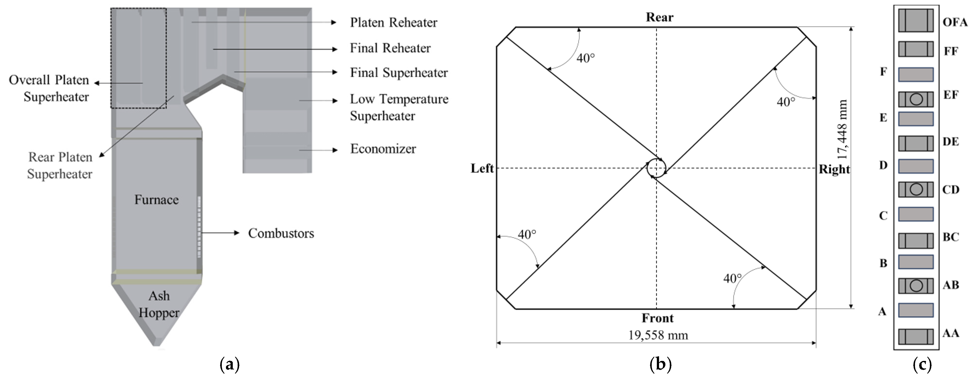
2.1. Research Object

In this study, a 600 MW tangentially fired furnace is selected as the research object. The firing mode is a four-corner tangential combustion arrangement, and three BBD4060A steel ball mills (Shenyang Heavy Power Station Equipment Manufacturing Co., Ltd. Shenyang, China) are equipped. The size of the boiler furnace is 34.0 m wide, 37.9 m deep, and 64.0 m high. Table 1 provides the main design parameters. The design coal and check coal of this project are Shenhua Wanlichuan bituminous coal. The coal’s ultimate and proximate analysis for boiler design is displayed in Table 2.
The minimum load of 58% (353 MW) was selected as the practical stability limit for pulverized coal combustion without auxiliary support, consistent with operational data from 600 MW boilers where loads below 55–60% exhibit significant combustion instability [41]. Ultra-low loads (<40%) require burner structural modifications beyond the flow optimization scope [42].

2.2. Computational Model and Verification

2.2.1. Physical Model and Grid Division

The main components of the furnace include an ash hopper, furnace, overall platen superheater, rear platen superheater, platen reheater, final reheater, final superheater, low temperature reheater, and economizer. The water-cooled wall and heat exchangers at all levels are simplified without thickness. The physical model is established according to the boiler’s physical construction. The overall structure is displayed in Figure 1.
Ansys ICEM CFD 2022 R1 is applied to mesh the boiler’s three-dimensional model. The mesh of the burner nozzle region is encrypted to ensure accurate simulation. The processed model grid structure is illustrated in Figure 2.
To calculate gradients across all variables, the Least Squares Cell-Based method—the default option in Fluent—is employed [43]. This approach is well-suited to the computational demands of large boiler models, ensuring both acceptable computational cost and accurate, stable gradient evaluation on the unavoidable unstructured mesh elements encountered in such complex geometries [44].

2.2.2. Boundary Conditions

The boiler load variation is primarily translated into the thermal boundary condition via the fuel feed rate. Higher load demands a proportional increase in the mass flow rate of pulverized coal injected into the furnace, thereby elevating the total heat input and the core combustion zone temperature. Correspondingly, the flow boundary conditions (primary and secondary air mass flow rates at the inlets) are scaled proportionally with the boiler load. This scaling ensures the stoichiometric air-fuel ratio is maintained across different operating loads while simultaneously affecting the inlet velocity profiles and the overall momentum of the gas flow within the furnace. Therefore, for each simulated load case (e.g., 353 MW, 600 MW), the key simulation inputs—namely the pulverized coal mass flow rate and the combustion air mass flow rates—were directly derived by scaling their respective design values according to the ratio of the operating load to the rated boiler capacity. Load-specific design parameters and combustion settings are provided in Table 3 and Table 4.
The Lagrangian discrete phase model was employed to simulate pulverized coal particle trajectories. The coal particle size distribution followed a Rosin–Rammler distribution with a minimum diameter of 0.01 mm, a maximum diameter of 0.25 mm, and a mean diameter of 0.056 mm. The spread parameter (polydispersity index) was set to 1.5, and the particle sizes were discretized into 10 groups to resolve polydisperse characteristics.

2.2.3. Mathematical Model

Coal particles were modeled as spheres within the Lagrangian framework. This spherical representation is commonly employed in full-scale boiler CFD studies for its computational efficiency and has been shown to provide reliable predictions of bulk flow behavior in large-scale industrial systems involving particulate flow [45]. The thermophysical properties of the coal particles, including specific heat capacity, thermal conductivity, and radiation absorption coefficient, are detailed in Table 5.
Fluent fluid calculation software was employed for the steady-state calculation. The particle–gas flow coupling was modeled as a two-way interaction within the Discrete Phase Model (DPM) framework. The Standard k ε two-equation turbulence model is selected to ensure the simulation accuracy [46]. The fundamental control equations comprise the energy equation, the momentum equation, the continuity equation, and the state equation. Choosing the Weighted-Sum-of-Gray-Gases (WSGGM) model to simulate the gas absorption coefficient [47]. In addition, the Discrete Ordinates (DO) method is adopted to calculate the radiative heat transfer [48]. To resolve radiative intensity gradients, 2 × 2 divisions (32 directions) and 3 × 3 pixels are adopted, ensuring robustness on unstructured meshes while limiting computational cost. The SIMPLE (Semi-Implicit Method for Pressure-Linked Equations) algorithm was employed to resolve pressure-velocity coupling [49]. The combustion of gas phase and carbon phase will be described by the finite rate/eddy dissipation model and the kinetic/diffusion-controlled reaction rate model. And the mass, momentum, and energy balance equations controlling the volume are as below:
ρ t + ( ρ u ) = S m
t ( ρ u ) + ( ρ u u ) = p + ρ g + S mv
t ( ρ E ) + ( v ( ρ E + ρ R T ) ) = ( λ eff T ) + S h
where ρ is the working medium density, kg·m−3; p is the working pressure, MPa; E is the total energy of the working medium, J·kg−1; R is the gas constant, J·mol−1·K−1; T is the working medium temperature, K; λ eff is the effective thermal conductivity, W·m−1·K−1; Sm, Smv and Sh are mass source term, kg·m−3·s−1, momentum source term, kg·m−2·s−2, and energy source term, W·m−3, respectively.
After the furnace’s combustion calculation has converged, the Oka model in Fluent is selected to predict the wall wear rate. The model comprehensively considers the material hardness of the collision wall and the characteristics of the collision, including the angle and speed of the solid particles. The Oka model was selected for wear rate prediction due to its well-established validity for erosive wear by coal particles impacting metallic surfaces, as demonstrated in both controlled experiments and studies of power plant components [50]. The model reliably captures the dependence of erosion rate on impact velocity, angle, and particle/material properties, making it particularly suitable for comparative analysis of wear mitigation strategies in this study. The material properties and impact conditions predicted by the CFD simulations fall within the validated range of the model parameters. The wear rate calculation formula of the Oka model is:
E = E 90 V / V r e f k 2 d / d r e f k 3 f ( γ )
E 90 = k H v k 1
f ( γ ) = ( sin γ ) n 1 1 + H v ( 1 sin γ ) n 2
where E is the wear rate, E90 is the wear rate when the particles impact with the wall vertically at 90°, kg·s−1·m−2; Hv is the material hardness of the impacted surface; V is the impact velocity of particles, m·s−1; Vref is the reference velocity of particles, m·s−1; d is particle diameter, m; dref is reference diameter, m; the other parameters are related to the characteristics of the wall particles, and the specific values are shown in Table 6.
The heat transfer between the flue gas and coal particles was comprehensively modeled by enabling bidirectional energy coupling to dynamically resolve temperature exchange between the discrete and continuous phases. Convective heat transfer was calculated through the energy equation, while radiative transfer was simulated using the DO method to account for direction-dependent radiation absorption and scattering by particles.

2.2.4. Grid Independence Verification

Several groups of models with separate numbers of meshes are selected for grid-free verification, and the uniform temperature of the horizontal interface at each height is observed (as shown in Figure 3). From the figure, the trend in average temperature at the horizontal interface of the furnace under several sets of grids is the same as that of the height. The simulation accuracy of the two sets of grids, with the number of grids of 1,342,284 and 1,657,720, is high. However, as the mesh becomes denser, compared with the grid group with the number of grids of 107,382, the calculation time and the computational resources will also increase. Considering the calculation accuracy and the computational resources consumed, this study selects the model of 1,342,284 grid for simulation.

2.2.5. Model Verification

Compared with the boiler design values, verification confirms the reliability of results from numerical simulation. The results are displayed in Table 7. From the table, the gas temperature deviation at the furnace outlet is 0.29%, while the deviation at the rear screen inlet is 0.51%. It is believed that the reliability of the selected numerical model is preferable.

3. Results and Discussion

3.1. Velocity Analysis

The gas phase velocity field can directly reflect the flow characteristics of pulverized coal flow and affect its combustion. Thus, it is imperative to analyze the law for reasonable optimization. In general, the airflow gradually diffuses after entering the furnace from the nozzle, leading to a steady decline in airflow rigidity along the direction of the jet. In addition, in the four-corner tangential boiler, the airflow will be affected by the adjacent corner airflow and change direction, and finally form a tangential circle with a good filling degree in the core combustion zone. The velocity near the center of the tangent circle and the wall is low, and flue gas flows back on the fire side and the back root of the primary air. This is beneficial to the pulverized coal particles’ ignition and combustion.
Figure 4 exhibits the air flow velocity distribution in the cross-section of the furnace nozzle under different loads. A tangent circle is created in the furnace by the four-corner airflow. The tangent circle’s diameter is larger than the imaginary tangent circle’s diameter. And the low-speed zone in the furnace is presented, which conforms to the general law of the four-corner tangent circle. As the boiler load goes up, the air flow velocity escalates significantly. Under the load of 353 MW, the maximum and minimum flow velocities of air flow on the cross-section are 12.7 m·s−1 and 0.426 m·s−1, respectively. When the load increases to 600 MW, these parameters escalate significantly, with maximum velocity reaching 33.2 m·s−1 and minimum velocity rising to 1.78 m·s−1. This substantial increase in velocity magnitude has profound implications beyond flow structure. Higher velocities generally reduce particle residence time within specific furnace zones. However, the observed development of a more coherent circular pattern and the ~15% expansion of the tangent circle diameter (from 353 MW to 600 MW) indicate a crucial compensating effect. The enlarged rotational flow path effectively increases the overall trajectory length for particles and gases within the core combustion zone before they exit upwards. As the load went up from 353 MW to 600 MW, the tangential airflow in the furnace developed a more coherent circular pattern, with the tangent circle diameter expanding by approximately 15% due to intensified rotational momentum and enhanced aerodynamic symmetry under higher operating conditions. Increased fuel and air supply is accompanied by enhanced combustion reactions, generating greater flue gas production. This elevated mass flow rate directly increases gas velocity within the furnace. The resulting higher flow momentum causes the rotational airflow pattern to expand radially, thereby enlarging the tangent circle diameter. This expansion is beneficial for combustion efficiency at high load. The larger tangential circle improves the spatial distribution of combustion, promoting better mixing of fuel and air across a wider central area of the furnace. This enhanced mixing mitigates localized oxygen deficiency and leads to a more uniform temperature distribution radially. Consequently, while peak gas temperatures might not increase linearly with load, the volume of the furnace effectively utilized for combustion increases, contributing to higher overall heat release and more uniform heat flux distribution on the furnace walls. The observed velocity increase, coupled with the larger tangent circle, suggests a more vigorous and well-distributed combustion process at 600 MW, likely translating to improved burnout rates. As shown in Figure 4, airflow streamlines exhibit tangential distribution with rotational characteristics. This pattern is formed through aerodynamic interactions between adjacent combustion jets, creating directional modifications in horizontal velocity distribution.

3.2. Internal Temperature Distribution

Figure 5 indicates the gas temperature distribution of the boiler center longitudinal section. As the load grows, the overall temperature level rises notably, and the high-temperature zone’s range expands. Under the load of 353 MW, the high temperature area accounts for about 1/2 of the furnace area, and the maximum temperature is 1.75 × 10³ K. When the load reaches 600 MW, the maximum temperature does not change significantly, but the high temperature zone almost occupies the entire boiler interior, so the overall temperature rises markedly. This significant expansion of the high-temperature zone volume at 600 MW, despite a stable peak temperature, indicates a substantial increase in the furnace’s effective heat release capacity and a more uniform thermal load distribution radially. To meet the higher load demand, the working intensity of the boiler burner rises, the combustion rate accelerates, the fuel supply grows, and the release of heat from the combustion increases, which makes the volume of the primary zone expand. The temperature rises with height. It increases at the lower height and then decreases gradually at the higher height. This is owing to the absence of fuel combustion in the ash hopper area at the lower part of the furnace, so the temperature is significantly cooler than the temperature in the primary zone. As the height rises to the main burning area of the boiler center, the gas flow and the pulverized coal are fully mixed and burned violently, leading to an evident temperature growth in this area and the burner zone. While the height rises to the burnout area, the supply of air and pulverized coal is insufficient, and the combustion intensity is weakened. Meanwhile, the water-cooled wall’s heat exchange in the furnace makes the temperature continue to decrease, so the temperature gradually decreases. The temperature generally presents a “low-high-low” distribution. The gas temperature distribution above the primary zone in the figure adopts an obvious hump shape. Considering the gas velocity distribution in the transverse section, the reason lies in the boiler’s middle part is the most uniform zone of airflow distribution. The flue gas movement is stable, while the flow rate is moderate. Furthermore, the unburned pulverized coal and the oxygen provided by the overfire air are fully blended during the rising process. Different from the area near the furnace wall, it will not be subject to wall friction and water wall cooling, so it continues to burn in the central area and eventually generates a high-temperature region. With the surrounding wall unremittingly assimilating the flue gas heat, a significant decline in the outer air temperature and a mild decline in the inner air temperature. Finally, a hump-shaped temperature distribution is formed above the primary zone. This characteristic hump profile, sustained by central combustion intensity and peripheral cooling, directly shapes the longitudinal heat flux distribution on the furnace walls, typically exhibiting a peak corresponding to this high-temperature core zone.

3.3. Heat Flux Distribution

Figure 6 shows the heat flux distribution across the facing wall and the lateral wall of the boiler. The wall heat flux is negative, indicating that the wall is in an endothermic state, and the heat exchange in the boiler is dominated by radiant heat exchange. This dominance of radiation is further supported by the observed high-temperature zones within the furnace core, as radiant heat transfer scales strongly with the fourth power of absolute temperature. Higher absolute values of wall heat flux correspond to enhanced heat transfer rates and increased thermal energy absorption by the furnace wall. The figure shows that the heat absorption distribution on the furnace wall is positively correlated with the boiler load. The main factor is that when the boiler load increases, the air temperature level also rises, which consequently impacts the water-cooled wall heat absorption distribution. Under 353 MW load, the furnace wall’s maximum heat absorption is 2.29 × 10⁵ W∙m−2. As the load goes up to 600 MW, the maximum heat absorption increases to 2.75 × 10⁵ W∙m−2. The observed thermal absorption enhancement is primarily attributed to elevated combustion air temperatures governed by boiler load increments. Maximum furnace wall heat flux measurements demonstrate load-dependent characteristics, with values rising from 2.29 × 10⁵ W∙m−2 at 353 MW to 2.75 × 10⁵ W∙m−2 under 600 MW operation. The combustion between the horizontal plane of the primary air AB nozzle and the overfire air nozzle is the most intense, so the temperature level of this part is high, and a large amount of radiant heat is diffused around. This region corresponds to the peak heat flux observed along the furnace height, highlighting the direct link between localized combustion intensity, gas temperature profiles, and wall heat absorption patterns. Accordingly, the elevated thermal intensity in the furnace’s central zone enhances the radiant heat exchange between adjacent water walls significantly. While the ash-cooled hopper and the area above the flame angle have lower temperatures, the amount of radiation is less, and the water-cooled wall’s heat absorption is consequently lower. The side wall heat flux distribution shows asymmetry, as seen in the figure. This uneven pattern is caused by non-uniform mixing of pulverized coal and air flow in different furnace zones, which directly influences combustion efficiency. The distribution of heat flux can be improved by monitoring in real time to maintain combustion stability and adjusting operating parameters in time. Such mixing non-uniformity can lead to localized variations in oxygen concentration and temperature, creating pockets of differing combustion intensity that manifest as the asymmetric heat flux distribution on the walls.

3.4. Wear Analysis

Pipe wear on the heating surface of a coal-fired boiler is a main problem affecting the stable operation and safety of a coal-fired boiler. A large amount of ash is produced during the operation of the boiler by coal combustion flows with the airflow, causing a severe impact on various components in the furnace. The results of numerical simulations show that the most severely worn heating surfaces in the boiler are the low temperature superheater, final superheater, flame angle, and economizer. The severe wall wear in these areas is caused by the unequal distribution of ash particles, the high flue gas flow rate, and the rapid movement of ash particles. These critical wear zones often correlate strongly with regions of high local gas velocity (Figure 4), significant particle concentration, or where complex flow patterns (like the intense tangential rotation in the upper furnace near the flame angle) direct particles towards the walls. The maximum wear rates for these parts are summarized in Table 8. As the load grows, the maximum wear rate of the low-temperature superheater rises from 1.23 × 10⁻⁸ kg·m−2·s−1 to 1.12 × 10⁻⁶ kg·m−2·s−1, and the wear rate of the final superheater, flame angle, and economizer also rises. The primary reason is that increased boiler load enhances airflow, increasing jet velocities and overall gas movement in the furnace. This directly raises the speed and kinetic energy of coal/ash particles carried by the airflow. Under the action of inertia, the impact force generated when these particles collide with the internal parts of the furnace increases, and the probability of secondary collision of solid particles with the components increases, resulting in an amplification in the maximum wear rate of each component. Furthermore, elevated temperatures at higher loads (Figure 5) may slightly soften ash particles or alter their viscoplastic behavior, potentially influencing their erosion characteristics upon impact, although the dominant factor remains the kinetic energy increase. As demonstrated in Figure 7 that the maximum wear rate of the economizer is the fastest at all loads. It is 3.29 × 10⁻⁷ kg·m−2·s−1 at 353 MW load and 1.23 × 10⁻⁵ kg·m−2·s−1 at 600 MW load. The maximum wear rate increases by nearly 40 times. This stems from the fact that the wear rate exhibits direct proportionality to the square of flue gas velocity, almost. The economizer is located in the tail flue of the boiler with a small cross-sectional area. Higher boiler duty makes the flue gas velocity rise rapidly, so the wear rate escalates more. Spatial erosion distribution (Figure 8) with velocity contours would vividly illustrate how the highest wear zones in the economizer align precisely with the highest velocity channels. While the overall airflow velocity rises, especially close to the furnace wall significantly increases, it may cause the flame to wash the wall, which in turn makes the furnace surface slagging and the wear of the components in the furnace, resulting in the wall thinning, affecting the boiler’s performance and safety, jeopardizing the boiler’s safe operation. This “flame washing” effect is particularly detrimental in areas like the flame angle, where the intense tangential flow patterns (Figure 4) can concentrate high-velocity particle-laden streams against specific wall sections, leading to localized severe wear. To effectively reduce the wear, the following control measures can be taken: regular cleaning of the furnace ash, increasing the dust removal equipment, reducing the density of solid particles in the exhaust gas; install anti-wear cover or anti-wear plate in the wear-prone area; thermal spraying technology is applied on the surface of wear-prone parts to enhance their wear resistance.

4. Conclusions

The gas–solid two-phase flow characteristics in the furnace of a 600 MW tangentially pulverized coal boiler are simulated with a numerical method. The research focuses on the analysis of the operation characteristics of the boiler across a variety of load conditions and obtains the important parameters such as the distribution of airflow streamline, temperature field, wall heat flux distribution and the maximum wear rate of key components in the furnace, which supplies a theoretical foundation for enhancing boiler’s operational safety and combustion efficiency. The primary conclusions are as follows:
(1)
Under different load conditions, the air flow in the furnace is well filled. Due to the impact of the jet, the airflow in the furnace displays obvious rotational flow characteristics. The velocity distribution exhibits that in the boiler center exist a low-velocity region exists, the velocity in the surrounding area is high, and the velocity in the near-wall area decreases again. This flow field structure effectively improves the adherent phenomenon of the primary air jet and significantly minimizes the risk of slagging. The research confirms that with the load’s escalation, the overall flow velocity and near-wall flow velocity demonstrate a proportional growth. The maximum flow rate reaches 33.2 m∙s−1 at 600 MW load.
(2)
The furnace temperature field presents the distribution characteristics of “low-high-low” along the height direction. In the principal burning section, the coal-air mixing is sufficient, and the burning is violent, forming a temperature peak area, and the temperature distribution in the main burning zone’s upper part displays a “hump-shaped” temperature distribution, that is, the central area is hotter than the surrounding regions. Temperatures in the center area can reach over 1600 K. As the load increases, the primary zone expands, the burning intensity increases, and the overall temperature level increases significantly.
(3)
The heat flux distribution of the water wall is significantly correlated with temperature patterns. In the high-temperature combustion-intensive region, the water-cooled wall’s heat absorption reaches its peak. As the rise of boiler load, the area with higher heat absorption expands, and its maximum value also increases accordingly. An increase in load from 353 MW to 600 MW resulted in an enhancement of maximum heat absorption from 2.29 × 10⁵ W∙m−5 to 2.75 × 10⁵ W∙m−2. The water-cooled wall heat flow uniformity can be improved by real-time monitoring of furnace combustion and reducing load changes.
(4)
The study on the dynamics of fly ash particles illustrates that the velocity and kinetic energy of solid particles escalate with the escalation of the load, which leads to the growth of the wear degree of the boiler’s internal parts and water wall. Where the maximum wear rate of the coal economizer increases with load, its maximum wear rate increases nearly 40 times. The wear rate can be effectively reduced by adding dust removal equipment, regular cleaning, anti-wear equipment, and thermal spraying surface treatment technology to optimize the boiler’s operational reliability and stability.

Author Contributions

L.S.: investigation, data curation, methodology, writing—original draft. M.W.: conceptualization, writing—review and editing. P.C.: investigation, data curation, writing—original draft. Y.S.: conceptualization, writing—review and editing. L.D.: conceptualization, supervision, investigation, writing—review and editing. All authors have read and agreed to the published version of the manuscript.

Funding

This research was funded by the National Key R&D Program (2021YFF0600601), China.

Data Availability Statement

The original contributions presented in this study are included in the article. Further inquiries can be directed to the corresponding author.

Conflicts of Interest

Authors Lijun Sun and Miao Wang were employed by the company Huayuan Power Plant, State Grid Energy Hami Coal and Power Co., Ltd. Author Peian Chong was employed by the company Shanghai Power Equipment Research Institute Co., Ltd. The remaining authors declare that the research was conducted in the absence of any commercial or financial relationships that could be construed as a potential conflict of interest.

References

  1. Yu, G.; Liu, K.; Hu, Z.; Liu, N.; Xiao, X. Optimal scheduling of deep peak regulation for thermal power units in power grid with large-scale new energy. Electr. Power Eng. Technol. 2023, 42, 243–250. [Google Scholar]
  2. Xin, S.W.; Wang, H.; Li, J.B.; Wang, G.; Wang, Q.H.; Cao, P.Q.; Zhang, P.; Lu, X.F. Discussion on the Feasibility of Deep Peak Regulation for Ultra-Supercritical Circulating Fluidized Bed Boiler. Energies 2022, 15, 7720. [Google Scholar] [CrossRef]
  3. Ding, Y. Research on Deep Peak Shaving Performance of 1000 MW Ultra-Supercritical Coal-Fired Boiler. Power Gener. Technol. 2024, 45, 382–391. [Google Scholar]
  4. Belosevic, S.; Tomanovic, I.; Crnomarkovic, N.; Milicevic, A. Full-scale CFD investigation of gas-particle flow, interactions and combustion in tangentially fired pulverized coal furnace. Energy 2019, 179, 1036–1053. [Google Scholar] [CrossRef]
  5. Yin, C.; Caillat, S.; Harion, J.L.; Baudoin, B.; Perez, E. Investigation of the flow, combustion, heat-transfer and emissions from a 609 MW utility tangentially fired pulverized-coal boiler. Fuel 2002, 81, 997–1006. [Google Scholar] [CrossRef]
  6. Wang, Q.; Liu, J.; Fan, H.; Qin, T.; Huang, Y.; Wang, Y.; Wang, H. Novel Technologies of Flexible Coal-fired Power Generation to Support China Energy Transition: Boiler System and Turbine Generator System. Proc. Chin. Soc. Electr. Eng. 2024, 44, 7136–7166. [Google Scholar]
  7. Al-Abbas, A.H.; Naser, J.; Hussein, E.K. Numerical simulation of brown coal combustion in a 550 MW tangentially-fired furnace under different operating conditions. Fuel 2013, 107, 688–698. [Google Scholar] [CrossRef]
  8. Jiang, Y.; Lee, B.H.; Oh, D.H.; Jeon, C.H. Influence of various air-staging on combustion and NOX emission characteristics in a tangentially fired boiler under the 50% load condition. Energy 2022, 244, 123167. [Google Scholar] [CrossRef]
  9. Zhu, M.X.; Lu, H.; Zhao, W.J.; Huang, S.W.; Chang, X.Q.; Dong, L.J.; Kong, D.; Jing, X.H. A Numerical Study of Ash Deposition Characteristics in a 660 MW Supercritical Tangential Boiler. Adv. Theory Simul. 2023, 6, 2300133. [Google Scholar] [CrossRef]
  10. Drosatos, P.; Nikolopoulos, N.; Agraniotis, M.; Kakaras, E. Numerical investigation of firing concepts for a flexible Greek lignite-fired power plant. Fuel Process. Technol. 2016, 142, 370–395. [Google Scholar] [CrossRef]
  11. Li, M.J.; Tang, S.Z.; Wang, F.L.; Zhao, Q.X.; Tao, W.Q. Gas-side fouling, erosion and corrosion of heat exchangers for middle/low temperature waste heat utilization: A review on simulation and experiment. Appl. Therm. Eng. 2017, 126, 737–761. [Google Scholar] [CrossRef]
  12. Díez, L.I.; Cortés, C.; Pallarés, J. Numerical investigation of NOx emissions from a tangentially-fired utility boiler under conventional and overfire air operation. Fuel 2008, 87, 1259–1269. [Google Scholar] [CrossRef]
  13. Yan, L.B.; He, B.S.; Yao, F.; Yang, R.; Pei, X.H.; Wang, C.J.; Song, J.G. Numerical Simulation of a 600 MW Utility Boiler with Different Tangential Arrangements of Burners. Energy Fuels 2012, 26, 5491–5502. [Google Scholar] [CrossRef]
  14. Bhuiyan, A.A.; Naser, J. CFD modelling of co-firing of biomass with coal under oxy-fuel combustion in a large scale power plant. Fuel 2015, 159, 150–168. [Google Scholar] [CrossRef]
  15. Coringa, J.; Colaço, M.; Leiroz, A.J.K.; Oliveira, E. Numerical investigation for steam tubes temperature reduction in a four fuels tangentially fired boiler. Appl. Therm. Eng. 2020, 179, 115656. [Google Scholar] [CrossRef]
  16. Belosevic, S.; Sijercic, M.; Crnomarkovic, N.; Stankovic, B.; Tucakovic, D. Numerical Prediction of Pulverized Coal Flame in Utility Boiler Furnaces. Energy Fuels 2009, 23, 5401–5412. [Google Scholar] [CrossRef]
  17. Belosevic, S.; Sijercic, M.; Oka, S.; Tucakovic, D. Three-dimensional modeling of utility boiler pulverized coal tangentially fired furnace. Int. J. Heat Mass Transf. 2006, 49, 3371–3378. [Google Scholar] [CrossRef]
  18. Fang, Q.Y.; Musa, A.A.B.; Wei, Y.; Luo, Z.X.; Zhou, H.C. Numerical Simulation of Multifuel Combustion in a 200 MW Tangentially Fired Utility Boiler. Energy Fuels 2012, 26, 313–323. [Google Scholar] [CrossRef]
  19. Modlinski, N.; Janda, T. Mathematical procedure for predicting tube metal temperature in the radiant superheaters of a tangentially and front fired utility boilers. Therm. Sci. Eng. Prog. 2023, 40, 101763. [Google Scholar] [CrossRef]
  20. Liu, Y.C.; Fan, W.D.; Li, Y. Numerical investigation of air-staged combustion emphasizing char gasification and gas temperature deviation in a large-scale, tangentially fired pulverized-coal boiler. Appl. Energy 2016, 177, 323–334. [Google Scholar] [CrossRef]
  21. Madejski, P.; Taler, D.; Taler, J. Numerical model of a steam superheater with a complex shape of the tube cross section using Control Volume based Finite Element Method. Energy Convers. Manag. 2016, 118, 179–192. [Google Scholar] [CrossRef]
  22. An, J.X.; Luo, X.J. Numerical simulation of ash erosion in the selective catalytic reduction catalyst of power plant boiler. Energy Rep. 2022, 8, 1313–1321. [Google Scholar] [CrossRef]
  23. Gandhi, M.B.; Vuthaluru, R.; Vuthaluru, H.; French, D.; Shah, K. CFD based prediction of erosion rate in large scale wall-fired boiler. Appl. Therm. Eng. 2012, 42, 90–100. [Google Scholar] [CrossRef]
  24. Grochowalski, J.; Widuch, A.; Sladek, S.; Melka, B.; Nowak, M.; Klimanek, A.; Andrzejczyk, M.; Klajny, M.; Czarnowska, L.; Hernik, B.; et al. Technique for reducing erosion in large-scale circulating fluidized bed units. Powder Technol. 2023, 426, 118651. [Google Scholar] [CrossRef]
  25. Waclawiak, K.; Kalisz, S. A practical numerical approach for prediction of particulate fouling in PC boilers. Fuel 2012, 97, 38–48. [Google Scholar] [CrossRef]
  26. Liu, X.; Xue, X.; Li, H.; Jin, K.L.; Zhang, L.; Zhou, H. Numerical simulation and mathematical models of ash deposition behavior considering particle properties and operating conditions. Fuel Process. Technol. 2023, 245, 107743. [Google Scholar] [CrossRef]
  27. Mbabazi, J.G.; Sheer, T.J.; Shandu, R. A model to predict erosion on mild steel surfaces impacted by boiler fly ash particles. Wear 2004, 257, 612–624. [Google Scholar] [CrossRef]
  28. Fan, J.R.; Sun, P.; Chen, L.H.; Cen, K. Numerical investigation of a new protection method of the tube erosion by particles impingement. Wear 1998, 223, 50–57. [Google Scholar] [CrossRef]
  29. Jin, T.; Luo, K.; Fan, J.R.; Yang, J.S. Immersed boundary method for simulations of erosion on staggered tube bank by coal ash particles. Powder Technol. 2012, 225, 196–205. [Google Scholar] [CrossRef]
  30. Lin, N.; Lan, H.-Q.; Xu, Y.-G.; Cui, Y.; Barber, G. Coupled Effects between Solid Particles and Gas Velocities on Erosion of Elbows in Natural Gas Pipelines. Procedia Eng. 2015, 102, 893–903. [Google Scholar] [CrossRef]
  31. Shah, K.V.; Cieplik, M.K.; Betrand, C.I.; van de Kamp, W.L.; Vuthaluru, H.B. A kinetic-empirical model for particle size distribution evolution during pulverised fuel combustion. Fuel 2010, 89, 2438–2447. [Google Scholar] [CrossRef]
  32. Sciubba, E.; Zeoli, N. A study of sootblower erosion in waste-incinerating heat boilers. J. Energy Resour. Technol. Trans. ASME 2007, 129, 50–53. [Google Scholar] [CrossRef]
  33. Xu, L.J.; Cheng, L.M.; Ji, J.Q.; Wang, Q.H. Effect of anti-wear beams on waterwall heat transfer in a CFB boiler. Int. J. Heat Mass Transf. 2017, 115, 1092–1098. [Google Scholar] [CrossRef]
  34. Peng, W.S.; Cao, X.W. Numerical prediction of erosion distributions and solid particle trajectories in elbows for gas-solid flow. J. Nat. Gas Sci. Eng. 2016, 30, 455–470. [Google Scholar] [CrossRef]
  35. Sedrez, T.A.; Decker, R.K.; da Silva, M.K.; Noriler, D.; Meier, H.F. Experiments and CFD-based erosion modeling for gas-solids flow in cyclones. Powder Technol. 2017, 311, 120–131. [Google Scholar] [CrossRef]
  36. Parvaz, F.; Hosseini, S.H.; Elsayed, K.; Ahmadi, G. Numerical investigation of effects of inner cone on flow field, performance and erosion rate of cyclone separators. Sep. Purif. Technol. 2018, 201, 223–237. [Google Scholar] [CrossRef]
  37. Bech, J.I.; Johansen, N.F.J.; Madsen, M.B.; Hannesdóttir, A.; Hasager, C.B. Experimental study on the effect of drop size in rain erosion test and on lifetime prediction of wind turbine blades. Renew. Energy 2022, 197, 776–789. [Google Scholar] [CrossRef]
  38. Oka, Y.I.; Okamura, K.; Yoshida, T. Practical estimation of erosion damage caused by solid particle impact—Part 1: Effects of impact parameters on a predictive equation. Wear 2005, 259, 95–101. [Google Scholar] [CrossRef]
  39. Oka, Y.I.; Yoshida, T. Practical estimation of erosion damage caused by solid particle impact—Part 2: Mechanical properties of materials directly associated with erosion damage. Wear 2005, 259, 102–109. [Google Scholar] [CrossRef]
  40. Wang, W.Q.; Sun, Y.H.; Wang, B.; Dong, M.; Chen, Y.M. CFD-Based Erosion and Corrosion Modeling of a Pipeline with CO2 Containing Gas-Water Two-Phase Flow. Energies 2022, 15, 1694. [Google Scholar] [CrossRef]
  41. Cao, X.-l.; Pi, Z.-r.; Peng, H.-y.; Jiang, S.-j. Numerical simulation on combustion process of 600 MW W-flame boiler. J. Cent. South Univ. Sci. Technol. 2012, 43, 1185–1191. [Google Scholar]
  42. Xia, Y.; Cheng, L.; Zhang, J.; Wang, Q.; Fang, M. Numerical Study of Gas-Solid Flow Field in a 600 MW CFB Boiler with Anti-wear Beams. J. Power Eng. 2013, 33, 81–87. [Google Scholar]
  43. Li, P.; Bao, T.; Guan, J.; Shi, Z.F.; Xie, Z.X.; Zhou, Y.G.; Zhong, W. Computational Analysis of Tube Wall Temperature of Superheater in 1000 MW Ultra-Supercritical Boiler Based on the Inlet Thermal Deviation. Energies 2023, 16, 1539. [Google Scholar] [CrossRef]
  44. Xiao, G.Z.; Ye, Q.H.; Zhong, Z.P.; Jin, B.S. Numerical investigation on co-combustion of sludge and coal in a 660 MW pulverized coal boiler. Waste Manag. 2025, 202, 114814. [Google Scholar] [CrossRef]
  45. Chu, K.W.; Wang, B.; Yu, A.B.; Vince, A. Particle scale modelling of the multiphase flow in a dense medium cyclone: Effect of vortex finder outlet pressure. Miner. Eng. 2012, 31, 46–58. [Google Scholar] [CrossRef]
  46. Al-Abbas, A.H.; Naser, J. Numerical Study of One Air-Fired and Two Oxy-Fuel Combustion Cases of Propane in a 100 kW Furnace. Energy Fuels 2012, 26, 952–967. [Google Scholar] [CrossRef]
  47. Wang, Y.; He, Y.; Weng, W.B.; Wang, Z.H. Numerical simulation of ammonia combustion with coal in a 135 MW tangentially fired boiler. Fuel 2024, 370, 131831. [Google Scholar] [CrossRef]
  48. Jamaluddin, A.S.; Smith, P.J. Predicting radiative-transfer in axisymmetric cylindrical enclosures using the discrete ordinates method. Combust. Sci. Technol. 1988, 62, 173–186. [Google Scholar] [CrossRef]
  49. Yang, C.-x.; Zhu, X. Numerical simulation of trimming of double-suction impeller in high-head and high-speed boiler feed water pump. J. Lanzhou Univ. Technol. 2016, 42, 61–65. [Google Scholar]
  50. Arabnejad, H.; Mansouri, A.; Shirazi, S.A.; McLaury, B.S. Development of mechanistic erosion equation for solid particles. Wear 2015, 332, 1044–1050. [Google Scholar] [CrossRef]
Figure 1. Furnace model and burner arrangement. (a) furnace geometry; (b) furnace cross-section; (c) burner distribution.
Energies 18 03947 g001
Figure 2. Mesh division.
Energies 18 03947 g002
Figure 3. Mesh independence test.
Energies 18 03947 g003
Figure 4. Gas velocity distribution of the nozzle cross-section under different loads.
Energies 18 03947 g004
Figure 5. Temperature distribution on the longitudinal surface of the furnace under different loads.
Energies 18 03947 g005
Figure 6. The heat flux distribution of the front wall and the right wall of the furnace under different loads.
Energies 18 03947 g006
Figure 7. The maximum wear rate of some areas under different loads.
Energies 18 03947 g007
Figure 8. Spatial erosion distribution.
Energies 18 03947 g008
Table 1. Boiler main parameters.
ParameterBMCRECR
Superheated steam flow rate (t·h−1)2023.001760.00
Superheater outlet steam pressure (MPa)17.5017.29
Superheater outlet steam temperature (°C)541.0541.0
Reheat steam flow rate (t·h−1)1689.21482.0
Reheater inlet/Outlet steam pressure (MPa)3.95/3.753.46/3.28
Reheater inlet/Outlet steam temperature (°C)328.0/541.0315.0/541.0
Economizer inlet feedwater temperature (°C)281.0272.0
Economizer inlet feedwater pressure (MPa)19.2618.70
Boiler pressure (MPa)18.2718.35
Table 2. Properties of fuels.
ParameterUltimate Analysis (%)Proximate Analysis (%)Qnet, ar (kJ∙kg−1)
VarAarMarFCarCarHarOar *NarSar
Design coal27.8410.3914.8046.4652.202.470.988.420.7318.852
Check coal28.179.1219.8942.8250.902.700.5010.830.8218.160
* By difference.
Table 3. Boiler Design Operating Parameters.
Unit Load (MW)353431519600
Coal feed rate (t·h−1)206.92268.22309.32304.69
Primary air flow rate (t·h−1)481.63585.31561.46559.20
Secondary air flow rate (t·h−1)842.18959.191288.161512.86
Primary air temperature (K)373373373373
Secondary air temperature (K)625625625625
Main steam flow rate (t·h−1)189817601275871
Steam temperature (K)814814814807
Table 4. Burner Zone Classifications and Inlet Velocity Settings.
Unit Load (MW)353431519600
Burner inlet velocity
(m·s−1)
AA11.6713.2917.8520.96
A14.7714.7813.3214.65
AB20.9323.8432.0237.61
B17.3017.5615.9616.66
BC20.9323.8432.0237.61
C17.3117.9615.7817.58
CD20.9323.8432.0237.61
D15.6515.6114.0215.23
DE20.9323.8432.0237.61
E3.6418.9715.3916.71
EF20.9323.8432.0237.61
F6.186.0612.766.06
FF21.2824.2332.5538.22
OFA21.2824.2332.5538.22
Table 5. The thermophysical properties of the coal particles.
ParameterValue
Density (kg·m−1)1400
Specific heat (J·kg−1·K−1)1680
Vaporization temperature (K)400
Volatile component fraction (%)24.92
Binary diffusivity (m2·s−1)4 × 10⁻⁵
Swelling coefficient1.4
Burnout stoichiometric ratio2.67
Combustible fraction (%)59.43
Table 6. Parameter settings in the Oka wear model.
ParameterE90k1k2k3n1n2
Value6.0570.122.350.190.81.3
Table 7. The comparison between CFD results and boiler design values.
ParameterCFD ResultDesign ValueDeviation (%)
Furnace outlet temperature (K)134413400.29
Rear platen superheater outlet temperature (K)175117600.51
Furnace Outlet Gas Temperature (K)134413400.29
Lower Furnace Outlet Temperature (K)175117600.51
Working Fluid Temperature of Separator (°C)325.05328.000.90
Oxygen Content of the Flue Gas at Economizer Outlet (%)2.852.901.72
CO Content of the Flue Gas at Economizer Outlet (%)0.920.902.22
NOx Content of the Flue Gas at Economizer Outlet (mg∙m−3)331.4337.11.69
Table 8. Maximum wear rate.
Load (MW)Maximum Wear Rate (×10−5 kg·m−2·s−1)
Low-Temperature
Superheater
Final SuperheaterFlame AngleEconomizer
3530.001230.002720.001270.0329
3830.003690.004110.002430.0892
4070.002050.001790.009230.0823
4310.01260.01390.01220.138
4630.07410.01290.08600.154
4920.01180.03480.1520.104
5190.03080.05590.1850.740
5460.05070.2680.2410.270
5740.09790.2230.3571.21
6000.1120.2160.3821.23
Disclaimer/Publisher’s Note: The statements, opinions and data contained in all publications are solely those of the individual author(s) and contributor(s) and not of MDPI and/or the editor(s). MDPI and/or the editor(s) disclaim responsibility for any injury to people or property resulting from any ideas, methods, instructions or products referred to in the content.

