Article

An Analytical Method for Solar Heat Flux in Spacecraft Thermal Management Under Multidimensional Pointing Attitudes

1
National Key Laboratory of Spacecraft Thermal Control, Beijing Institute of Spacecraft System Engineering, Beijing 100094, China
2
School of Energy Science and Engineering, Harbin Institute of Technology, Harbin 150001, China
*
Authors to whom correspondence should be addressed.
Energies 2025, 18(15), 3956; https://doi.org/10.3390/en18153956
Submission received: 13 June 2025 / Revised: 16 July 2025 / Accepted: 18 July 2025 / Published: 24 July 2025

Abstract

In order to provide a theoretical basis for the thermal analysis and management of spacecraft/payload interstellar pointing attitudes, which are used for inter-satellite communication, this paper develops an analytical method for solar heat flux under pointing attitudes. The key to solving solar heat flux is calculating the angle between the sun vector and the normal vector of the object surface. Therefore, a method for calculating the included angle is proposed. Firstly, a coordinate system was constructed based on the pointing attitude. Secondly, the angle between the coordinate axis vector and solar vector variation with a true anomaly was calculated. Finally, the reaching direct solar heat flux was obtained using an analytical method or commercial software. Based on the proposed method, the direct solar heat flux of relay satellites in commonly used lunar orbits, including Halo orbits and highly elliptic orbits, was calculated. Thermal analysis on the payload of interstellar laser communication was also conducted in this paper. The calculated temperatures of each mirror ranged from 16.6 °C to 21.2 °C. The highest temperature of the sensor was 20.9 °C, with a 2.3 °C difference from the in-orbit data. The results indicate that the external heat flux analysis method proposed in this article is realistic and reasonable.

1. Introduction

In recent years, with the explosive growth in the amount of information transmitted by spacecraft, space laser communication technology has gained increasingly widespread application due to its high bandwidth, large transmission capacity, and small terminal size [1,2,3,4,5]. Establishing a globally covered satellite laser communication network is a growing trend. Additionally, relay satellite systems, as key hubs for space information transmission and efficient space-based telemetry and communication facilities, are widely used in tasks such as rendezvous and docking, lunar exploration, and satellite telemetry and control [6,7,8,9]. Both types of tasks require establishing connections between spacecraft, typically through the multidimensional movement of communication terminals and relay antennas on the spacecraft, and sometimes through attitude adjustments of the spacecraft itself to meet various pointing requirements. Therefore, these tasks need to be conducted under multidimensional pointing attitudes.
Space external heat flux has a significant impact on the thermal design of spacecraft. To determine the layout of heat dissipation surfaces and the extreme conditions for thermal analysis, it is essential to analyze space external heat flux [10,11,12]. Space external heat flux is the sum of all space thermal radiation reaching the spacecraft and is typically divided into three categories: solar heat flux, Earth albedo, and Earth infrared radiation. Among these, solar heat flux is the most variable and has the primary influence on the heat flux reaching relay satellites and high-orbit laser communication payloads [13,14,15]. Therefore, studying solar external heat flux is of great significance. A large body of research has been devoted to the analysis of external space heat flux. Liu et al. [16] conducted a thermal analysis on laser communication terminals of geostationary Earth orbit (GEO) satellites. Given that the optical axis of the antenna is predominantly directed toward the Earth’s center, they focused on analyzing the solar external heat flux incident on the Earth-facing surface and derived the variation pattern of external heat flux over one orbital period. Han et al. [17] investigated a satellite in a circular orbit with an altitude of 500 km and an inclination of 30°. Under the three-axis Earth-pointing attitude, they analyzed the external heat flux of the co-orbital inter-satellite laser communication terminal, which provided a basis for the selection of heat-dissipating surfaces. Liu et al. [18] proposed a fast calculation method for solar radiation heat flux. This method simplifies the positional relationships among the satellite, the Sun, and the Earth to reduce computational parameters, thereby enhancing computational efficiency, with a specific focus on calculating the external heat flux under the three-axis stabilized Earth-pointing attitude. Zhang et al. [19] established an analytical model for calculating external heat flux in inclined circular orbits and examined the variation characteristics of external heat flux under the three-axis stabilized Earth-pointing attitude. Yuan et al. [20] developed a space quadrant and intelligent occlusion calculation method for external heat flux computation of the China Space Station. The core of this method lies in its capability to intelligently determine complex spatial occlusion scenarios, though it does not account for the influence of complex attitudes. Zheng et al. [21] employed the Monte Carlo simulation approach to model the solar radiation, Earth-emitted radiation, and Earth albedo radiation received by space targets, with an emphasis on analyzing two commonly adopted attitudes: Earth-pointing and Sun-pointing. Krainova et al. [22] reviewed conventional methods for calculating external heat flux and proposed a methodology to determine external heat flux on arbitrarily oriented spacecraft surfaces based on trajectory data, incorporating the effect of spacecraft rotation about its longitudinal axis on heat flux. However, their computational method is relatively generalized, and the analysis results are limited to one-dimensional rotational attitudes, which are simpler compared to pointing attitudes. Yi et al. [23] put forward a method for calculating external heat flux on convex surfaces applicable to Keplerian orbits and analyzed the external heat flux of spacecraft under conventional orbital attitudes. This method is also restricted to relatively simple attitudes, and further research is required for the calculation of external heat flux under complex attitudes such as inter-satellite pointing. In summary, existing studies on the analysis and calculation of external heat flux have primarily focused on conventional attitudes such as three-axis stabilized Earth-pointing, while there is a paucity of research on external heat flux under complex attitudes like inter-satellite pointing.
Spacecraft and payloads usually have to undergo intricate maneuvers to achieve the inter-satellite pointing state. As a result, the geometric relationship between the spacecraft/payload and the Sun under the pointing attitude becomes more complex, leading to more complex variations in external heat flux. This complexity also renders the solution process for external heat flux more formidable. Consequently, to achieve more accurate and effective thermal control design for spacecraft and payloads under various inter-satellite pointing attitudes, it is imperative to conduct research on external heat flux under typical inter-satellite pointing attitudes.
Current established methods for calculating external heat flux are suitable for common attitude types, such as three-axis stabilized Earth-pointing attitude, but demonstrate limited applicability for complex attitudes. Building upon conventional algorithms, this study investigates the complex spatial relationships specific to pointing attitudes, with the goal of developing an external heat flux calculation method applicable to complex attitude scenarios. This research will provide a theoretical basis and data support for the corresponding thermal control design.
This paper addresses the problem of solving external heat flux for inter-satellite pointing attitudes and conducts research on the external heat flux analysis methods for spacecraft and payloads under inter-satellite pointing attitudes. Based on the proposed method, the solar heat flux reaching the satellite surfaces under two typical relay satellite orbits, namely the Halo orbit and the large elliptical frozen orbit, was calculated, and a thermal analysis of the laser communication payload was performed. The content of each section of this paper is as follows. Section 1 introduces the background and significance of the research. Section 2 describes the method for calculating solar direct heat flux under pointing attitudes. Section 3 calculates the solar heat flux reaching different surfaces of the satellite under Halo and large elliptical frozen orbits. Section 4 establishes a thermal simulation model for the inter-satellite laser communication payload and conducts thermal analysis under typical conditions using the external heat flux analysis method described in Section 2. Section 5 provides the conclusions of the paper.

2. Analysis Method for Direct Solar Heat Flux of Pointing Attitude

Before introducing the theoretical methodology, the assumptions underlying this study and the constructed model are first elaborated. Most satellite bodies are typically a hexahedron. In thermal analysis, it is necessary to calculate the external heat flux incident on each surface. Therefore, in the external heat flux analysis of this paper, we create a hexahedron as a simplified model of the satellite. The model has the following characteristics:
(1)
The satellite body is assumed to be a hexahedron;
(2)
All edge lengths of the satellite are set to 1 m;
(3)
All surfaces of the satellite are flat;
(4)
To intuitively evaluate the external heat flux incident on each surface, various protrusions on the satellite surface are neglected, and the satellite surface is assumed to be unobstructed with each face being a convex surface.
The analytical method proposed in this paper will be specifically introduced below.
The key to obtain the reaching direct solar heat flux on a certain surface is solving the angle between the solar vector and normal vector. Then, the solar heat flux reaching on different surfaces can be calculated by analytic method according to the geometry relationship. To determine the relationship, a coordinate system based on pointing attitude was first established. Considering the communication load is usually located on the +Z plane of the satellite, the pointing orientation was set as the positive direction of the Z coordinate axis. The three-axis stability nadir attitude is the basic attitude for satellites, and on the basis of the nadir attitude coordinate system, the pointing attitude coordinate system was constructed. First, the nadir attitude coordinate system was rotated around the Z axis. Then, the coordinate system was rotated around the Y axis. By these two rotations, the orientation of the +Z axis was changed from nadir to pointing direction, and the X and Y axis was also determined along with the Z axis. The pointing attitude coordinate system is shown in Figure 1. In this figure, A and B denote Satellite A and Satellite B, respectively, with the attitude vector directed from A to B; X, Y, and Z represent the axes of the nadir attitude coordinate system, respectively; and X’, Y’, and Z’ represent the axes of the pointing attitude coordinate system. Φ is the yaw angle and θ is the pitch angle; the dashed arrowed line denotes the projection of the pointing vector onto the XOY plane.
It can be seen that the key to solving the reaching solar heat flux is to obtain the yaw angle φ and the pitch angle θ. Once these two angles are certain, the coordinate system is fixed, and the relationship between solar vector and satellite can also be determined. Therefore, the core of this analysis method is coordinate system transformation, namely calculating the rotation angles.
Firstly, the nadir attitude coordinate system is rotated around the Z axis, to make the +X axis reach the projection of pointing vector on the XOY plane. Assuming the angle between pointing vector and +X axis of nadir attitude coordinate system is α, the angle between the pointing vector and +Y axis of the nadir attitude coordinate system is η, and the angle between the pointing vector and +Z axis is γ, the yaw angle φ can be described as shown in Figure 2. In this Figure, a denotes the unit vector of the pointing vector.
Considering that the projection of the pointing vector on the XOY plane can be in different quadrants, the calculation situation is divided into four parts:
(1)
The projection is in the first quadrant, namely η < 90° and α < 90°:
According to the spatial geometric relation, the yaw angle φ can be described as follows:
tan ϕ = cos η cos α ϕ = arctan cos η cos α
(2)
The projection is in the second quadrant, namely η < 90° and α > 90°:
tan ( π ϕ ) = cos η cos π α = cos η cos α
Namely,
ϕ = π + arctan cos η cos α
(3)
The projection is in the third quadrant, namely η > 90° and α > 90°:
tan ( ϕ π ) = cos π η cos π α = cos η cos α
Namely,
ϕ = π + arctan cos η cos α
(4)
The projection is in the fourth quadrant, namely η > 90° and α < 90°:
tan 2 π ϕ = cos π η cos α = cos η cos α tan ϕ 2 π = cos η cos α
ϕ = 2 π + arctan cos η cos α
Thus,
ϕ = arctan cos η cos α ,                         η < 90 ° , α < 90 ° π + arctan cos η cos α ,                 α > 90 ° 2 π + arctan cos η cos α ,     η > 90 ° ,   α < 90 °
Through the above analysis, it can be seen that while η > 90°, the projection of the pointing vector is in the third or fourth quadrant, and the yaw angle φ is greater than 180°; conversely, φ is smaller than 180°. Additionally, there are some special cases:
(1)
While α = 90°, the pointing vector is in the YOZ plane. According to the geometric relation, the yaw angle φ = 90° (while η < 90°) or 270° (while η > 90°).
(2)
While η = 90°, the pointing vector is in the XOZ plane. According to the geometric relation, the yaw angle φ = 0° (while α ≤ 90°) or 180° (while α > 90°). In this case, the pointing vector is in the orbital plane. According to the position of the satellite relative to the object, the pointing attitude can be divided into forward pointing attitude and backward pointing attitude. For the forward pointing attitude, the object is in front of the satellite, namely in the +X direction of the satellite. In this case, there is no need for yaw to realize the pointing attitude, which matches the situation of α ≤ 90°. As for the backward pointing attitude, the object is at the back, which means α > 90°. To point to the object, the satellite should turn from the flight direction to the opposite flight direction, hence the yaw angle is 180°.
Once the yaw is completed, the direction of coordinate system is certain. Then, the coordinate system should be rotated around the Y axis, and the pitch angle is determined as follows:
θ = γ
By two rotations, the +Z axis is transferred into the pointing vector, and the pointing attitude coordinate system is obtained. With the established coordinate system, the reaching solar heat flux can be computed by analytic methods or commercial software.
The formula for calculating direct solar heat flux is [18]:
q SUN = S max M 1 cos Φ sin Φ cos Ι sin Φ sin Ι x y z , 0
In the equation, S is the solar constant, Ι is the obliquity of the ecliptic, Φ is the solar ecliptic longitude, [x,y,z]T is the unit normal vector of a given surface point in the orbital coordinate system. For a three-axis stabilized Earth-pointing attitude, the transformation matrix from the spacecraft body frame to the orbital frame is a third-order identity matrix. The pointing attitude frame proposed in this study is derived from the Earth-pointing frame by applying pitch and yaw rotations. The corresponding rotation transformation matrix is given by:
M x = 1 0 0 0 1 0 0 0 1
M y = cos θ 0 sin θ 0 1 0 sin θ 0 cos θ
M z = cos ϕ sin ϕ 0 sin ϕ cos ϕ 0 0 0 1
In the equation, Mx, My, and Mz represent the rotation transformation matrices around the X, Y, and Z axes, respectively. As described earlier, the transformation from the Earth-pointing attitude frame to the pointing attitude frame involves a rotation around the Z-axis, then a rotation around the Y-axis. Thus, the total rotation matrix M is expressed as:
M = M z M y M x
For surfaces of different geometries, the unit normal vector [x,y,z]T can be calculated using the method described in [23]. By combining Equations (10) and (14), the direct solar heat flux on any surface at any given time can be computed. It should be noted that this analytical method is only applicable to calculating the external heat flux on convex surfaces, and the computed results represent the first-arrival heat flux rather than the absorbed heat flux by the surface. For concave surfaces, where different faces are mutually visible, direct solar heat flux undergoes multiple reflections after reaching the surface. Consequently, the final incident heat flux becomes closely related to both the geometric configuration between surfaces and their optical properties, making the calculation more complex. Regarding absorbed heat flux, the surface absorptivity must also be considered. However, for typical spacecraft external surfaces, particularly radiator surfaces, they are generally designed to be unobstructed to achieve optimal thermal dissipation performance and can therefore be treated as convex surfaces. Using the aforementioned analytical method, the incident heat flux on various spacecraft surfaces can be evaluated, providing valuable references for the selection of radiator surfaces on spacecraft.
In commercial software, data interfaces are typically provided to allow direct input of constructed arrays or expressions—composed of yaw/pitch angles calculated according to Equations (8) and (9) and orbital time (or true anomaly)—into the orbital setup module of the model. By utilizing the software’s generic external heat flux solver, the transient heat flux on spacecraft/payload surfaces under inter-satellite pointing attitudes can then be computed. These software packages commonly employ the Monte Carlo method for external heat flux calculations.

3. Analysis of Reaching Solar Heat Flux of Lunar Relay Satellite

3.1. Analysis of External Heat Flux for Relay Satellites in Halo Orbit

Based on the proposed analysis method, the reaching solar heat flux on relay satellites in Halo orbit and elliptic frozen orbit is calculated.
The Halo orbit and elliptic frozen orbit are normal long-term orbits for relay satellite [24]. In these two cases, the attitude of the satellite is coincident. While the relay satellite performs tasks, the load, such as an antenna which is usually located on the +Z plane, may point to the explorer on the Moon or the ground station on Earth for communication, namely in the pointing attitude. Additionally, the satellite should yaw to ensure exposure of the solar arrays. Furthermore, while the load is not functioning, the satellite may point to the Sun to secure energy supplies. Because the attitude of relay satellites is varied and complex, to simplify the calculation process, this paper only considers the pointing attitude and ignores the change of attitude in one track. In fact, any attitude can be transformed from the nadir attitude by the proposed method. The pointing attitude in this paper is defined as follows: the +Z axis points to the subject on the Moon (explorer or south pole of the Moon), and the +Y vector is the cross product of the +Z vector and solar vector. The +X axis is determined according to the right-hand rule [24].
An Earth–Moon L2 point Halo orbit is the mission orbit of Chang’e-4 relay satellite, and the orbit plane of the Halo orbit is a space curved face. First, translate the satellite into a regular hexahedron with a flat surface and establish a hexahedral model in TD software. Assuming each face of the model has an edge length of 1 m and all satellite surfaces share identical optical properties, both the absorptivity and emissivity are set to 1.
Based on the three-axis Earth-pointing attitude, input the calculated yaw and pitch angles according to the computation method in Section 2 to configure the pointing attitude. Calculation results of the solar heat flux on different surfaces are shown in Figure 3 and Figure 4.
In this attitude, the +Y axis is perpendicular to the solar vector. Hence, the solar heat flux on ±Y plane is 0. From Figure 3 and Figure 4, it can be seen that the solar heat flux varies wildly. Unlike conventional orbits that operate within a single plane, the Halo orbit is a three-dimensional spatial trajectory, resulting in more complex variations in external heat flux. The orbital period of the Halo orbit is 30 days. Analysis results reveal that when the satellite maintains its pointing attitude throughout the orbital cycle, the illumination trends on the +X and −X surfaces follow identical patterns, differing only in their temporal phasing. The trends on the +Z and −Z surfaces also follow the same patterns.

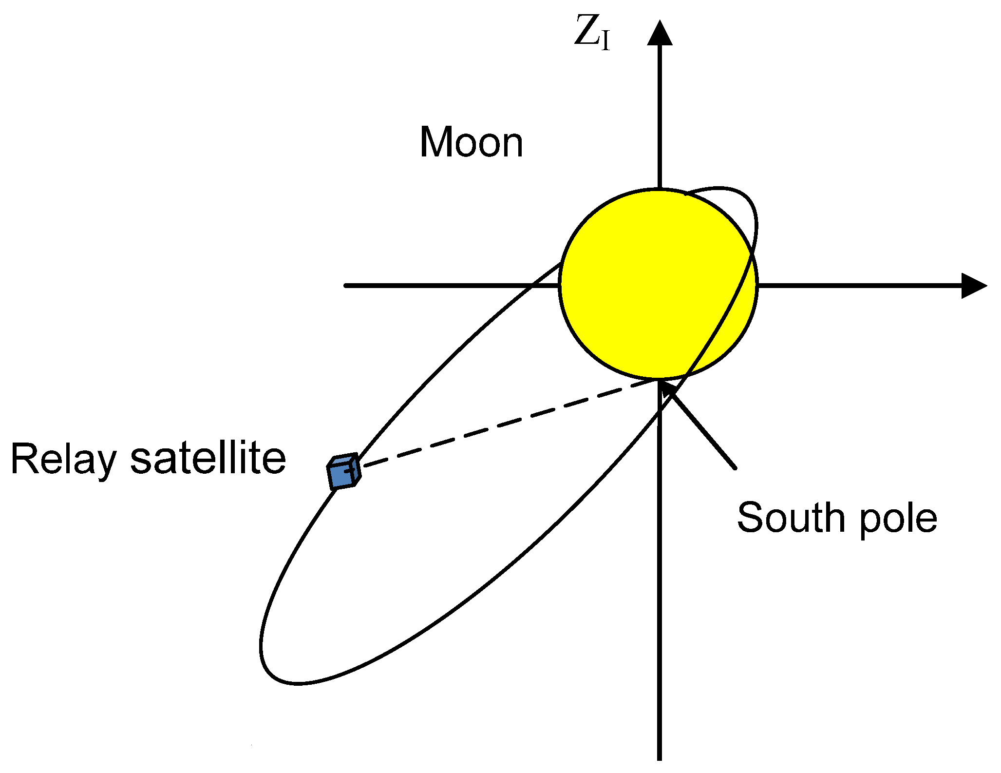
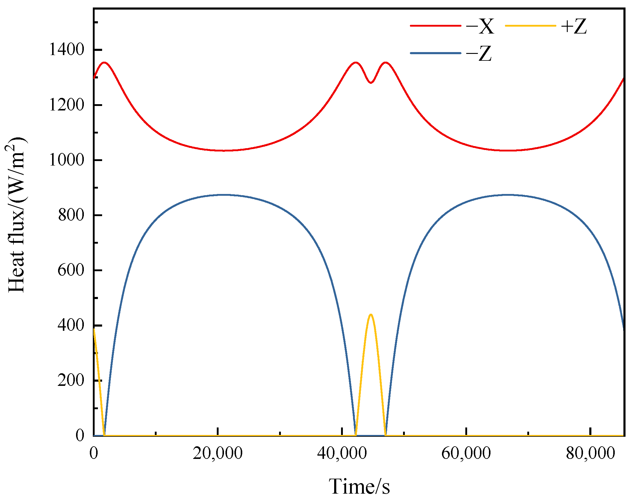
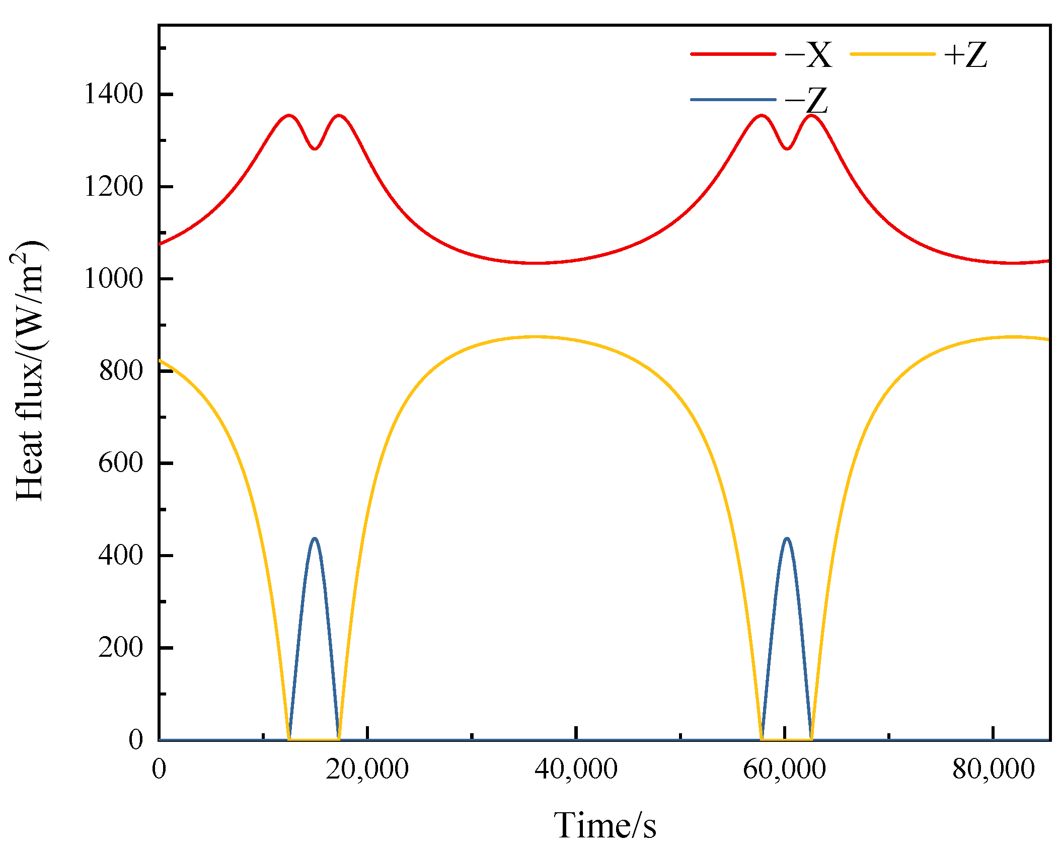
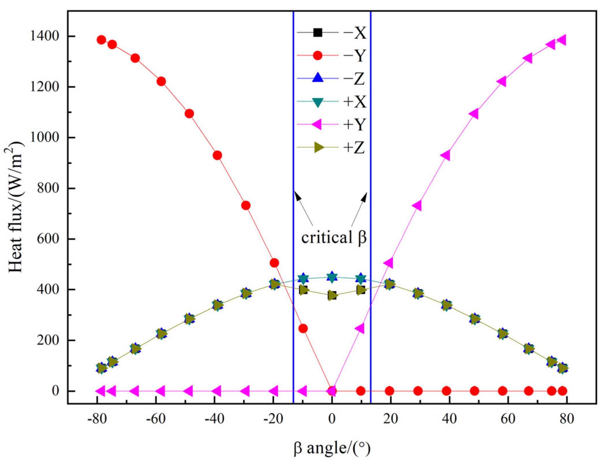
3.2. Analysis of External Heat Flux for Relay Satellites in Elliptic Orbit

Parameters of the elliptic orbit can be obtained from [25]. The elliptic orbit is shown in Figure 5. In this diagram, the dash line denotes the schematic representation of the direction from the satellite to the lunar south pole.
Besides the attitude, the included angle between the solar vector and orbital plane, namely beta angle β, also has a great influence on the reaching solar heat flux [10]. For the inclined orbit mentioned above, β varies from −56° to +56°. To analyze extreme conditions, we considered β as 0°, −56°, and +56°. In this chapter, the satellite model is the same as the model established in Section 3.1.
(1)
β = 0°
Calculation results of the solar heat flux on different surfaces when β = 0° are shown in Figure 6. In this case, the transient solar heat flux of two orbital periods was calculated to show the variety.
For the proposed pointing attitude, the +Y axis is perpendicular to the solar vector. Hence, the solar heat flux on the ±Y plane is 0. According to the geometric relationship, the included angle between the +X axis and solar vector is smaller than 90°, which means that the +X plane cannot be illuminated.
The variety of the solar heat flux on the ±Z plane and −X plane can be seen in Figure 6. When β = 0°, there will be a moment when the −X plane is perpendicular to the solar vector, and the ±Z plane is parallel to the solar vector at the same time. Therefore, the maximum solar heat flux on the −X plane is equal to the solar constant. The −Z plane and +Z plane cannot be illuminated simultaneously, but the variety of the solar heat flux is symmetrical about the sub-solar point, and the maximum is close to the solar constant.
(2)
β = −56°
Calculation results when β = −56° are shown in Figure 7. Because the attitude is the same as that when β = 0°, the ±Y plane and +X plane are not illuminated, either.
(3)
β = 56°
From Figure 6, Figure 7 and Figure 8, it can be seen that the reaching solar heat flux on different surfaces is significantly influenced by the angle of β. When β = 0°, the maximum solar heat flux on ±Z plane is greater, but the mean value of a period on the +Z plane is greater when β = 56° and on the −Z plane it is greater when β = −56°. Solar heat flux varies more violently when β = 0°, and is greater when β = ±56°. Additionally, the variety of solar heat flux on the −X plane is the same when β = −56° and β = 56°.
A comparison of external heat flux results between Halo and highly elliptical orbits reveals that, within one orbital period, both orbit types exhibit identical variation trends in heat flux on both +Z and −Z surfaces. Under pointing attitude conditions, the ±Y surfaces remain unilluminated with zero absorbed heat flux. These analytical results provide valuable references for spacecraft radiator surface selection. Surfaces with higher absorbed heat flux should be thermally insulated to prevent heat ingress into the spacecraft interior, while surfaces with lower absorbed heat flux are more suitable as radiators. Consequently, the ±Y surfaces may be considered as primary radiator surfaces, with ±Z surfaces serving as auxiliary ones. Notably, orbital characteristics affect surface illumination differently: in Halo orbits the +X surface experiences periodic illumination, whereas in highly elliptical orbits it remains unilluminated. Therefore, for satellites in highly elliptical orbits, the +X surface may also be designated as a primary radiator surface.

4. Thermal Analysis of Interstellar Laser Communication Payload

The interstellar laser communication payload primarily performs functions such as interstellar network communication and ranging. Therefore, it maintains an interstellar pointing attitude while in orbit. This section applies the external heat flux analysis method for interstellar pointing attitude proposed in Section 2 to the thermal analysis of the interstellar laser communication payload. Considering the interstellar pointing attitude of the laser communication payload, a typical high-temperature scenario is selected, and the temperature results for key components of the payload are calculated and compared with in-orbit temperatures.

4.1. Analysis of External Heat Flux

The orbital parameters are set as shown in Table 1, which is a typical medium Earth orbit (MEO) of navigation satellite [26]. Assume that Satellite A is a regular hexahedron with each edge measuring 1 m, and all surfaces of the satellite have identical optical properties, with both absorptivity and emissivity set to 1. The pointing attitude is from Satellite A to Satellite B.
For a circular orbit with an inclination of 55°, the β angle varies between −78.5° and +78.5°. The cycle-averaged external heat flux of Satellite A for different β angles is shown in Figure 9. It can be observed from the figure that the variation trends of the average heat flux on all faces are symmetric about the β angle. Physically, the β angle fundamentally governs the symmetry and periodicity of solar illumination relative to the spacecraft body axes. A constant β results in a fixed geometric relationship where the Sun’s apparent path relative to the satellite repeats identically each orbital period. This deterministic illumination geometry dictates the range and temporal pattern of incident heat flux, irrespective of which specific faces are exposed due to attitude differences [10].
The transient external heat flux variations for several typical β angles (minimum β angle 0°, critical β angle 13.2°, and maximum β angle 78.5°) are shown in Figure 10.
For this type of orbit, the critical β angle is 13.2°. When the β angle is greater than 13.2°, the orbit is a full sunlight orbit with no shadow zones. In this case, the peak external heat flux on the ±X and ±Z surfaces is the same and is given by the solar constant ×cosβ. The instantaneous values differ only in phase. The cycle-averaged external heat flux is the same for both surfaces and is given by the solar constant ×cosβ/π. When the β angle is less than 13.2°, the influence of shadow zones causes differences in the illumination conditions of the ±X and ±Z surfaces, leading to different cycle-averaged external heat flux values. For the ±Y surfaces, at the same β angle, only one surface is illuminated while the other has zero external heat flux. For the illuminated surface, the external heat flux remains constant during the illumination period and is given by the solar constant ×sin(|β|). During the shadow period, the external heat flux is zero. The orbital parameters in [26] are identical to those in this section, with the difference lying in the attitude configuration. In [26], the satellite adopts a yaw-steering attitude, where the satellite maintains Earth-pointing along the +Z axis while ensuring the ±Y and −X faces remain unexposed to solar radiation. In contrast, this work employs a pointing attitude where any satellite face may be illuminated. Nevertheless, for the illuminated faces, the variation range of the heat flux remains identical and the variation trend is similar under the same β angle. This is because the coordinate transformation for the pointing attitude is performed based on the +Z Earth-pointing attitude, analogous to yaw steering control. The difference arises from the distinct rotation axes, resulting in different illuminated faces.

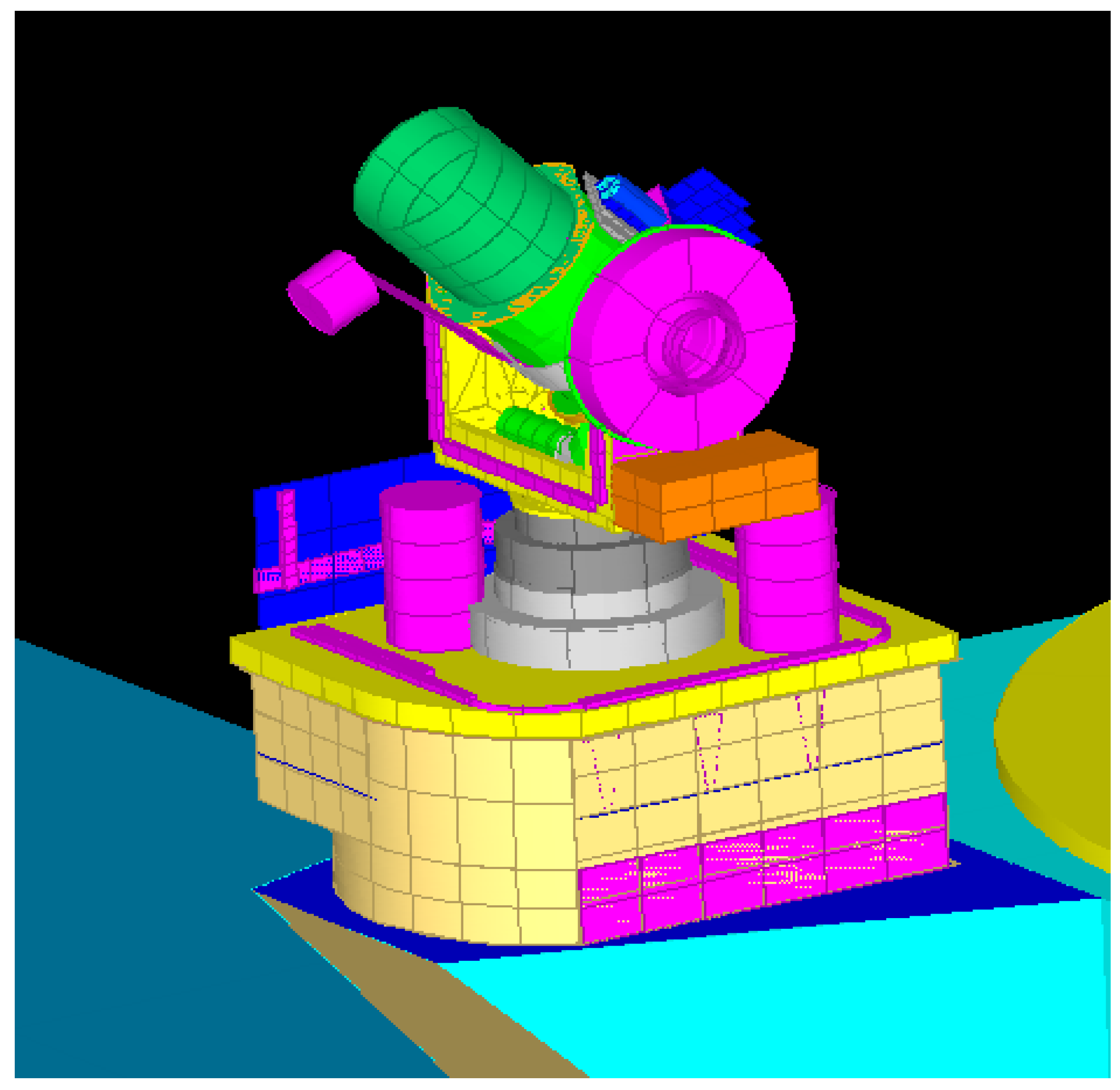
4.2. Modeling of Inter-Satellite Laser Communication Payload

The thermal control configuration of the inter-satellite laser communication payload is as follows. White paint is applied on the telescope barrel and baffle surfaces; black paint is applied on the inner surface of the optical tube; black anodizing is adopted for primary mirror skin, secondary mirror skin, tertiary mirror skin, quaternary mirror skin, primary mirror mount, secondary mirror mount, and tertiary mirror mount. Based on these thermal control design specifications, a 3D thermal simulation model for the inter-satellite laser communication payload has been established, as shown in Figure 11. For the satellite, continuous yaw control is performed to ensure that the Sun always remains within the XOZ plane of the satellite’s body coordinate system. This means that the sunlight is always parallel to the ±Y faces of the satellite, with the +X face continuously illuminated and the −X face not illuminated. The payload’s angle tracking range is as follows: pitch from −70° to 70° within a conical angle, and azimuth from 0° to 360°.

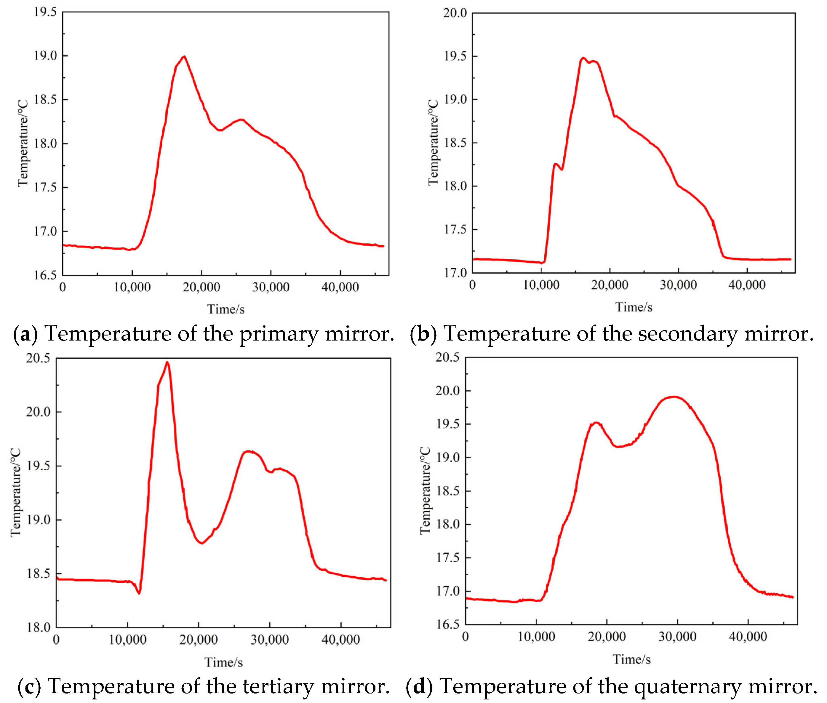
4.3. Payload Thermal Analysis of Typical Operating Conditions for Inter-Satellite Laser Communication Payload

The payload can experience high temperatures under the following conditions: (1) forward tracking at β = 13.2°, (2) backward tracking at β = 13.2°. According to the analysis in Section 4.1, when β = 13.2°, the entire satellite is in a full-sunlight orbit. For both forward and backward tracking modes, the exposure conditions of the payload are symmetrical, resulting in the same average external heat flux over the orbit period and the same maximum instantaneous external heat flux, with only a phase difference. Therefore, we will focus on the backward tracking condition at β = 13.2° for this section’s analysis.
During the simulation, the satellite maintains a yaw attitude relative to the Sun, and the payload maintains an inter-satellite pointing attitude. The yaw and pitch angles are set according to the methods described in Section 2. Figure 12 shows the temperature variation curves for the primary mirror, secondary mirror, tertiary mirror, and quaternary mirror under the inter-satellite pointing attitude. Table 2 lists the maximum and minimum temperatures of each mirror, and Table 3 provides the calculation results as well as the maximum and minimum temperatures of the primary mirror tube measured in orbit.
Under the inter-satellite pointing attitude, the calculated temperatures of each mirror range from 16.6 °C to 21.2 °C. Considering the in-orbit measurement results from the temperature sensors on the primary mirror barrel, four temperature sensors are arranged on the primary mirror barrel. The results show that the simulation results based on the inter-satellite pointing attitude are close to the in-orbit measurement values. The highest temperature under the inter-satellite pointing attitude is 20.9 °C, which differs from the in-orbit measured temperature by 2.3 °C. Therefore, using the external heat flux method for the inter-satellite pointing attitude proposed in this paper, the external heat flux conditions in orbit can be accurately analyzed, providing a theoretical basis for the thermal analysis of the payload under the pointing attitude.

5. Conclusions

This paper addresses the issue of external heat flux analysis for inter-satellite pointing attitudes and proposes an external heat flux analysis method for complex inter-satellite pointing attitudes. Numerical simulations of solar external heat flux for typical lunar relay satellite orbit were conducted to validate the feasibility of the method. Finally, the method was applied to the thermal analysis of inter-satellite laser communication payloads, providing the temperature results of key payload components and comparing them with in-orbit measurement results. The conclusions of this paper are as follows:
(1)
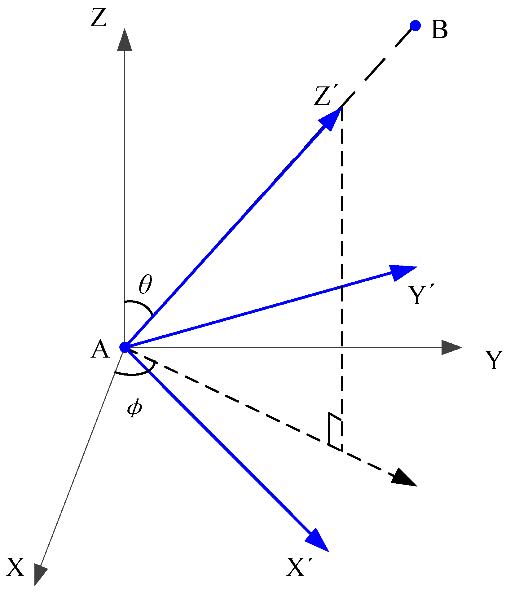
A complex external heat flux analysis method for inter-satellite pointing attitudes has been proposed. A coordinate system for inter-satellite pointing attitudes was established, based on a three-axis Earth-pointing coordinate system. The +Z axis is rotated from Earth-pointing to the inter-satellite pointing vector direction through yaw and pitch. The calculation methods for yaw and pitch angles during coordinate system transformation were analyzed. Using the satellite orbit parameters and the calculated yaw and pitch angles, the external heat flux on each surface of the inter-satellite pointing attitude can be obtained using space thermal analysis software.
(2)
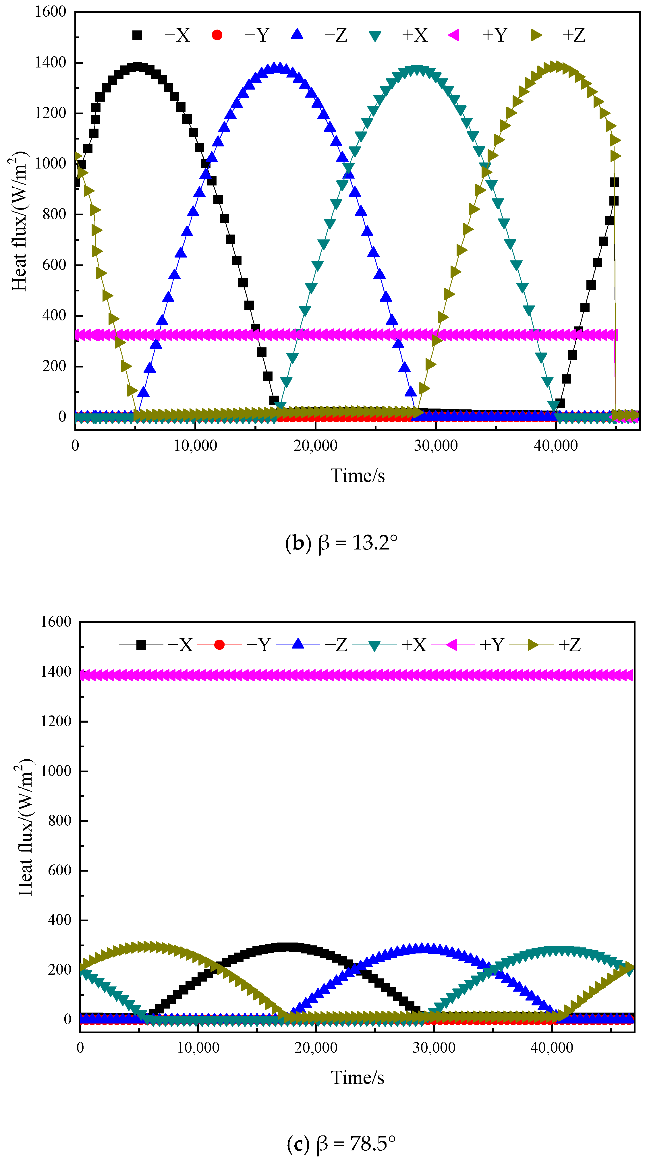
The solar heat flux for lunar relay satellites in Halo orbits and large elliptical frozen orbits was analyzed. For inclined elliptical orbits, the transient heat flux on each surface at different β angles was calculated, and the variations of solar heat flux were analyzed. This provides data references for thermal control design of relay satellites in inclined large elliptical orbits.
(3)
The temperature comparison results of key components of the laser communication payload show that the operational mode based on inter-satellite pointing attitudes aligns with its in-orbit operational conditions. The temperature calculation results obtained using the external heat flux analysis method for inter-satellite pointing attitudes matched the in-orbit temperatures. Therefore, the proposed analysis method is reasonable and feasible, and can provide references and bases for thermal control design of spacecraft/payloads in inter-satellite pointing attitudes.
The comprehensive analytical method for direct solar heat flux calculation proposed in Chapter 2 of this study, while specifically applicable to first-incidence heat flux computation on convex surfaces, can be extended to more complex scenarios. For concave surfaces or surfaces with complex optical properties, as well as for absorbed heat flux calculations, radiation exchange factors between surfaces can be obtained through many methods, such as ray-tracing or the Monte Carlo method. Subsequently, based on the known first-incidence heat flux, both the actual incident heat flux and absorbed heat flux can be determined.
Therefore, for future research, the methodology presented in this paper can serve as a foundation to develop more generalized absorbed external heat flux calculation approaches suitable for complex surface characteristics. Such advancement would enhance the method’s universality and provide more accurate computational techniques for spacecraft thermal analysis.

Author Contributions

Conceptualization, X.H. and T.L.; methodology, X.H. and H.Y.; validation, X.H. and H.Y.; formal analysis, X.H. and H.Y.; resources, Y.Z. and Y.R.; writing—original draft preparation, X.H. and T.L.; writing—review and editing, X.H., Y.Z., F.X. and Y.R. All authors have read and agreed to the published version of the manuscript.

Funding

This research was funded by National Key Research and Development Program of China (2022YFC2204400).

Data Availability Statement

The data that support the findings of this study are available from the corresponding author upon reasonable request.

Conflicts of Interest

Authors Xing Huang, Tinghao Li, Hua Yi, Yupeng Zhou, and Feng Xu were employed by the National Key Laboratory of Spacecraft Thermal Control (Beijing Institute of Spacecraft System Engineering). Author Yatao Ren was employed by Harbin Institute of Technology. The remaining authors declare that the research was conducted in the absence of any commercial or financial relationships that could be construed as a potential conflict of interest.

References

  1. Wang, T.S.; Lin, P.; Dong, F.; Liu, X.Z.; Ma, W.Z.; Fu, Q. Progress and Prospect of Space Laser Communication Technology. Eng. Sci. 2020, 22, 92–99. [Google Scholar] [CrossRef]
  2. Liu, C.; Li, X.Y.; Zhang, K.H.; Lan, B.; Dai, T.J.; Xian, H. Research Progress and Future Directions in Deep Space Optical Communication. Laser Optoelectron. Prog. 2024, 61, 84–93. [Google Scholar]
  3. Liu, Z.; Jiang, Q.F.; Liu, S.T.; Tian, S.Q.; Zhu, L.Y.; Liu, X.Z.; Yu, J.X.; Zhao, J.T.; Yao, H.F.; Dong, K.Y. Research progress of space laser communication networking technology. Chin. Opt. 2025, 18, 429–451. [Google Scholar] [CrossRef]
  4. Yu, H.H.; Lu, S.W.; Hu, Q.; Fan, Y.B.; Zhu, F.N.; Xia, H.W.; Li, J.W.; Sun, J.F.; Hou, X.; Chen, W.B.; et al. In-orbit intersatellite laser communication experiment based on compound-axis tracking. Chin. Opt. Lett. 2025, 23, 42–48. [Google Scholar] [CrossRef]
  5. Carrizo, C.; Knapek, M.; Horwath, J.; Diaz Gonzalez, D.; Cornwell, P. Optical inter-satellite link terminals for next generation satellite constellations. In Proceedings of the Free-Space Laser Communications XXXII, San Francisco, CA, USA, 2 March 2020. [Google Scholar]
  6. Li, T.; Liu, B.G.; Tang, D.; Zhang, Q.Q. Space-Based TT&C and Communication Mode for Space Station. Aerosp. Shanghai 2023, 40, 134–139. [Google Scholar]
  7. Liu, B.G.; Wu, B. Application of TDRSS in Chinese Space TT&C. J. Spacecr. TT C Technol. 2012, 31, 1–5. [Google Scholar]
  8. Zhang, L.H.; Xiong, L.; Sun, J.; Gao, S.; Wang, X.L.; Zhang, A.B. Technical characteristics of the relay communication satellite “Queqiao” for Chang’e-4 lunar farside exploration mission. Sci. Sin. Technol. 2019, 49, 138–146. [Google Scholar] [CrossRef]
  9. Yang, M.F.; Zhang, G.; Zhang, W.; Ruan, J.H.; Huang, H.; Peng, J.; Deng, X.J.; Shi, W.; Wang, Y.; Zhang, H.H.; et al. Technical design and implementation of Chang’e-6 robotic sample return mission on the far side of the moon. Sci. Sin. Technol. 2025, 55, 1133–1146. [Google Scholar] [CrossRef]
  10. Zhao, X. Study on Change Rule of β Angle for Various Orbits in Satellite Thermal Design. Spacecr. Eng. 2008, 17, 57–61. [Google Scholar]
  11. Dou, Q.; Li, J.D.; Zhu, J.; Zhou, Y. Analysis on heat flux fluctuation and its inhibition strategies for agile satellite camera. Spacecr. Environ. Eng. 2014, 31, 62–67. [Google Scholar]
  12. Li, Z.S.; Ma, C.J.; Mao, Y.J.; Guo, T.; Wang, X.; Mou, X.N. Rapid analysis of temperature field for orbiting nanosatellites. Spacecr. Environ. Eng. 2021, 38, 122–129. [Google Scholar]
  13. Meng, H.H.; Geng, L.Y.; Li, G.Q. Thermal control design and experiment for laser communication equipment. Infrared Laser Eng. 2014, 43, 2295–2299. [Google Scholar]
  14. Mei, K.; Song, Y.W.; Liang, L.; Du, J.D.; Fu, S.; Jiang, Y.J. The effect of temperature characteristic variation due to thermal control design on the antenna of satellite laser communication terminals. In Proceedings of the 6th Global Conference on Materials Science and Engineering, Beijing, China, 24–27 October 2017. [Google Scholar]
  15. Liu, H.; Tan, J.; Tang, Z.B.; Ge, Z.J. Thermal control design and experimental verification of optical terminals for laser communication payloads of a satellite system. Spacecr. Environ. Eng. 2024, 41, 55–60. [Google Scholar]
  16. Liu, B.L.; Zhou, Z.X.; Li, J.; Tan, L.Y. Thermal control of optical antenna for spaceborne laser communication in geostationary orbit. Chin. J. Lasers. 2017, 44, 0306003. [Google Scholar]
  17. Han, Y.L.; Li, S.J.; Xie, T. Thermal control design and verification of co-orbital inter-satellite laser communication terminal. Spacecr. Environ. Eng. 2025, 42, 159–166. [Google Scholar]
  18. Liu, X.; Pan, Z.F. Simplified Calculating Method of the Sun Radiation Flux for On-orbit Satellite. Chin. Space Sci. Technol. 2012, 4, 15–21. [Google Scholar]
  19. Zhang, H.; Cao, J.G.; Wang, J.; Zeng, F.J. Analysis of Satellite’s Extreme Heat Flow in Inclined orbit. Aerosp. Shanghai. 2018, 35, 36–42. [Google Scholar]
  20. Yuan, M.; Li, Y.Z.; Sun, Y.H.; Ye, B.P. The space quadrant and intelligent occlusion calculation methods for the external heat flux of China space Station. Appl. Therm. Eng. 2022, 212, 1359–4311. [Google Scholar] [CrossRef]
  21. Zheng, H.R.; Ma, Y.; Zhang, S.; Wang, J.C.; Qu, Y.Y. Calculation of orbit external heat flow and radiation characteristics of space target. Chin. Opt. 2024, 17, 187–197. [Google Scholar] [CrossRef]
  22. Krainova, I.V.; Nenarokomov, A.V.; Nikolichev, I.A.; Titov, D.M.; Chumakov, V.A. Radiative Heat Fluxes in Orbital Space Flight. J. Eng. Thermophys 2022, 31, 441–457. [Google Scholar] [CrossRef]
  23. Yi, H.; Huang, X.; Zhou, Y.P. Study on general calculation method for external heat flux on convex surfaces on spacecraft in Keplerian orbit. Spacecr. Eng. 2024, 33, 59–64. [Google Scholar]
  24. Gao, S.; Zhou, W.Y.; Zhang, L.; Liang, W.G.; Liu, D.C.; Zhang, H. Trajectory design and flight results for Chang’e 4-relay satellite. Sci. Sin. Technol. 2019, 49, 156–165. [Google Scholar] [CrossRef]
  25. Zhou, W.Y.; Gao, S.; Liu, D.C.; Zhang, X.Y.; Ma, J.N.; Yu, D.Y. Orbit design for lunar polar region exploration. J. Deep Space Explor. 2020, 7, 248–254. [Google Scholar]
  26. Lin, S.F.; Li, K.; Lin, B.J.; Jiang, G.Z.; Ma, E.R. Thermal Control Design and Validated for MEO Navigation Satellites. Chin. J. Space Sci. 2022, 42, 144–152. [Google Scholar] [CrossRef]
Figure 1. Schematic diagram of pointing attitude coordinate system.
Energies 18 03956 g001
Figure 2. Schematic diagram of yaw angle.
Energies 18 03956 g002
Figure 3. Results of the solar heat flux on ±X plane.
Energies 18 03956 g003
Figure 4. Results of the solar heat flux on ±Z plane.
Energies 18 03956 g004
Figure 5. Schematic diagram of elliptic frozen orbit.
Energies 18 03956 g005
Figure 6. Results of solar heat flux on different surfaces when β = 0°.
Energies 18 03956 g006
Figure 7. Results of solar heat flux on different surfaces when β = −56°.
Energies 18 03956 g007
Figure 8. Results of solar heat flux on different surfaces when β = 56°.
Energies 18 03956 g008
Figure 9. Cycle-averaged external heat flux of Satellite A for different β angles.
Energies 18 03956 g009
Figure 10. Transient external heat flux variations on Star A’s surfaces over one orbital period.
Energies 18 03956 g010aEnergies 18 03956 g010b
Figure 11. Thermal simulation model of the inter-satellite laser communication payload.
Energies 18 03956 g011
Figure 12. Temperature variation curve of each mirror over time under inter-satellite pointing attitude.
Energies 18 03956 g012
Table 1. Interstellar pointing attitude external heat flux calculation conditions setting.
Orbital ParametersA SatelliteB Satellite
Altitude (km)21,58621,586
Eccentricity (°)00
Inclination (°)5555
Argument of Periapsis (°)00
Longitude of the Ascending Node (°)180180
True Anomaly (°)0−90
Table 2. Maximum and minimum temperatures of each mirror (°C).
ComponentMinimum TemperatureMaximum Temperature
Primary Mirror16.619.3
Secondary Mirror17.119.5
Tertiary Mirror18.321.2
Quaternary Mirror16.820.0
Table 3. Comparison of calculation results and in-orbit data (°C).
ThermistorCalculation ResultIn-Orbit Data
Minimum ValueMaximum ValueMinimum ValueMaximum Value
TZT10218.520.518.719.2
TZT10318.520.618.519.1
TZT10418.420.918.523.2
TZT10518.819.518.622.9
Disclaimer/Publisher’s Note: The statements, opinions and data contained in all publications are solely those of the individual author(s) and contributor(s) and not of MDPI and/or the editor(s). MDPI and/or the editor(s) disclaim responsibility for any injury to people or property resulting from any ideas, methods, instructions or products referred to in the content.

