


The Possibility of Using Hydrogen as a Green Alternative to Traditional Marine Fuels on an Offshore Vessel Serving Wind Farms


Abstract
1. Introduction
1.1. Research Background
- Design and construction changes to the ship’s hull;
- Weight and volume of fuel tanks and their impact on the ship layout (engine room and adjacent compartments), as well as the possibility of installing them in the ship’s hull;
- Solutions and configuration of the ship’s energy system;
- Cargo carrying capacity and displacement of the vessel;
- Operational parameters, including vessel speed and range.
- Issues of using alternative fuels such as LNG or methanol (MeOH) are discussed, but the use of hydrogen fuel is still in an experimental phase, and research is limited to smaller coastal vessels;
- No information is available on the impact of fuel type on the design process and ship construction and performance, i.e., the main dimensions, functional–spatial layout of the hull, deadweight or total displacement of the ship;
- For special vessels, i.e., service vessels (apart from a few examples with design plans), there is a lack of scientific publications on the effects and possibilities of using hydrogen fuel with strict safety rules;
- There are no data on the use of hydrogen for direct combustion in reciprocating internal combustion engines used in ship energy systems and thus on the impact of such a solution on the functional and spatial parameters of the ship.
1.2. Hydrogen Properties, Storage and Maritime Transport
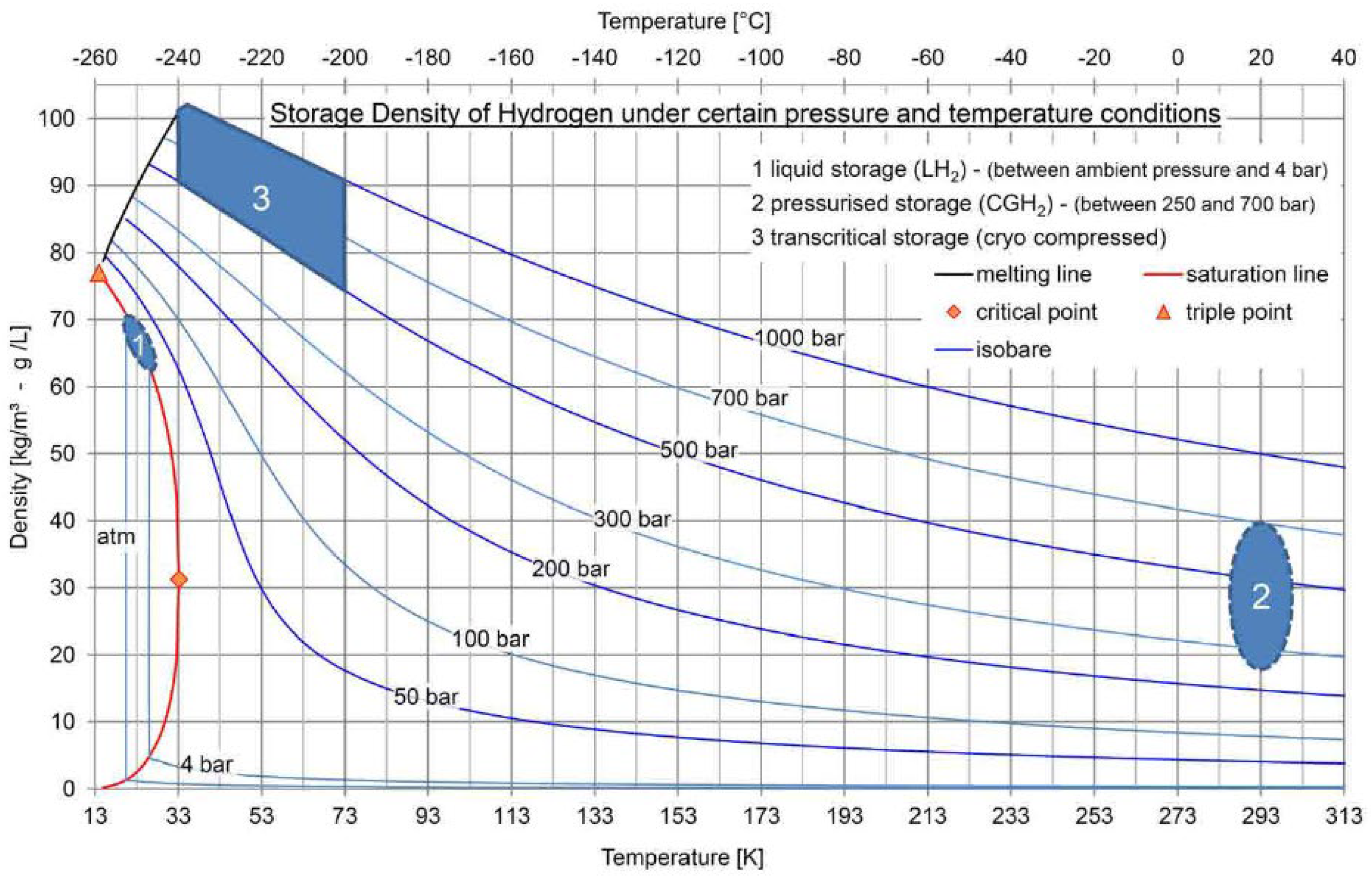
- Liquefied hydrogen transported in cryogenic tanks (−253 °C);
- Compressed hydrogen transported in metal, high-pressure tanks (older solution) and in composite tanks or high-pressure vessels, i.e., tanks (recent solution).
- NPROXX, based in the Netherlands;
- Hexagon Purus, with a seat in Ålesund, Norway.
1.3. The Use of Hydrogen in Internal Combustion Engines
- The 31H2 dual-fuel engine, which can run on natural gas or hydrogen, as well as a mixture of these fuels;
- The 31SG-H2 engine, which can run on natural gas and a mixture of natural gas and hydrogen up to 25 per cent by volume; can also be adapted to run on hydrogen alone.
1.4. Research Aim
- Analyse the physical and chemical properties of hydrogen and the challenges posed by the use of hydrogen on board as a fuel;
- Apply the technical requirements for the safe operation of hydrogen fuel (storage and transport) in accordance with current IMO guidelines;
- Carry out a power demand analysis for the main SOV operating regimes in the area of wind farms located in the Baltic Sea;
- Select the number and power of commercially available compressed hydrogen engines and analyse their configurations;
- Calculate fuel consumption for different ship operating regimes, select the storage and transport system and deploy their elements in the hull, meeting safety requirements;
- Analyse the impact of the use of hydrogen fuel on the design and structural elements and spatial layout of the ship;
- Identify what benefits will be achieved with the different fuels, taking into account the hull volume used, resulting from the volume of the fuel tanks selected;
- Conduct an economic analysis in terms of the cost of the hydrogen fuel used and make a rough comparison with other accepted fuels such as MDO, LNG and MeOH.
2. Initial Assumption and Methodology
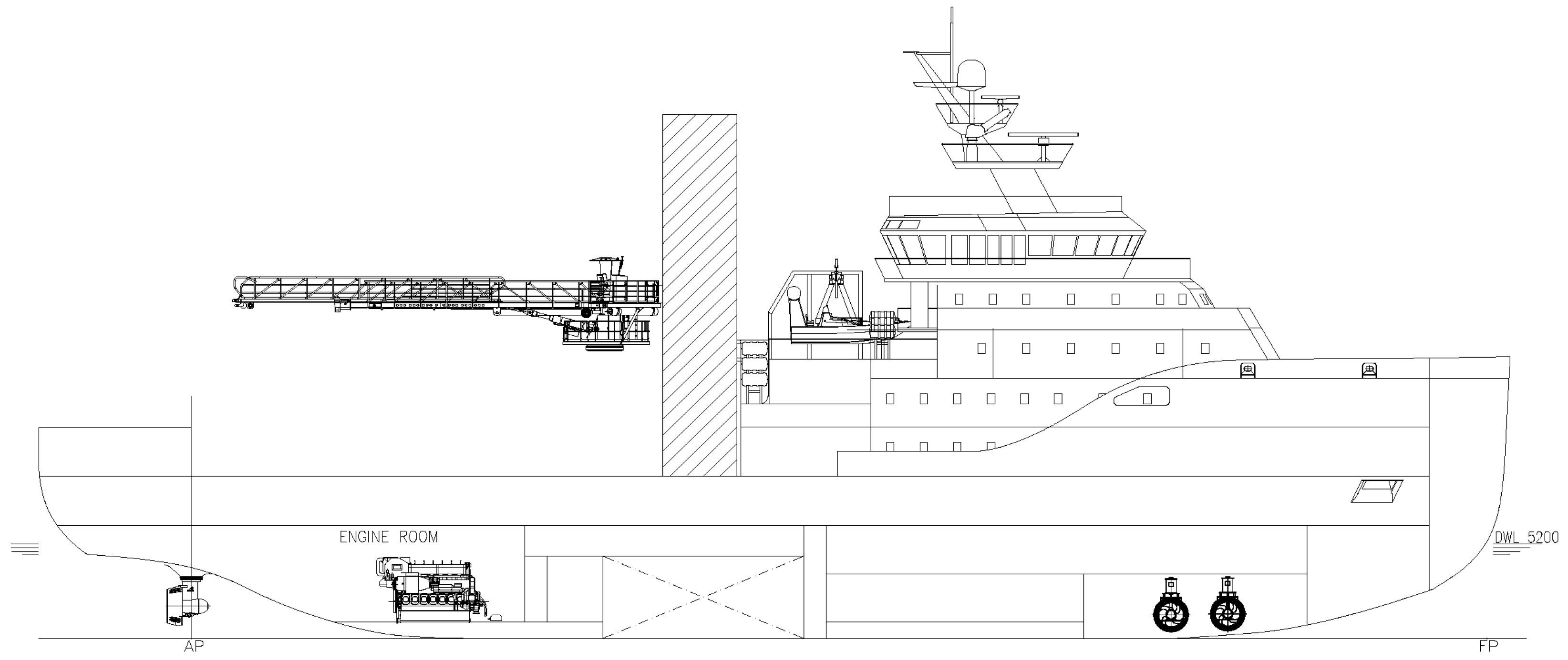
2.1. Specification of the Service Vessel and Its Area of Work
- Wärtsilä 20 four-stroke diesel engine (Wärtsilä Corporation, Helsinki, Finland), which can run on marine diesel oil (MDO) and light and heavy fuel oil (LFO, HFO);
- Wärtsilä 20DF four-stroke dual-fuel diesel engine (Wärtsilä Corporation, Helsinki, Finland), that can run on liquified natural gas (LNG), MDO and HFO;
- Wärtsilä 20 methanol-fuelled four-stroke diesel engine (Wärtsilä Corporation, Helsinki, Finland), which, in addition to methanol, can run on MDO, LFO and HFO;
- BEH2YDRO DZD H2 four-stroke hydrogen-fuelled diesel engine (BeHydro, Gent, Belgium), which can run on MDO and LFO in addition to hydrogen.
2.2. Hydrogen Fuel Storage and Transport on a Service Offshore Vessel
- Technology for transporting hydrogen in compressed form at high pressure—700 bar;
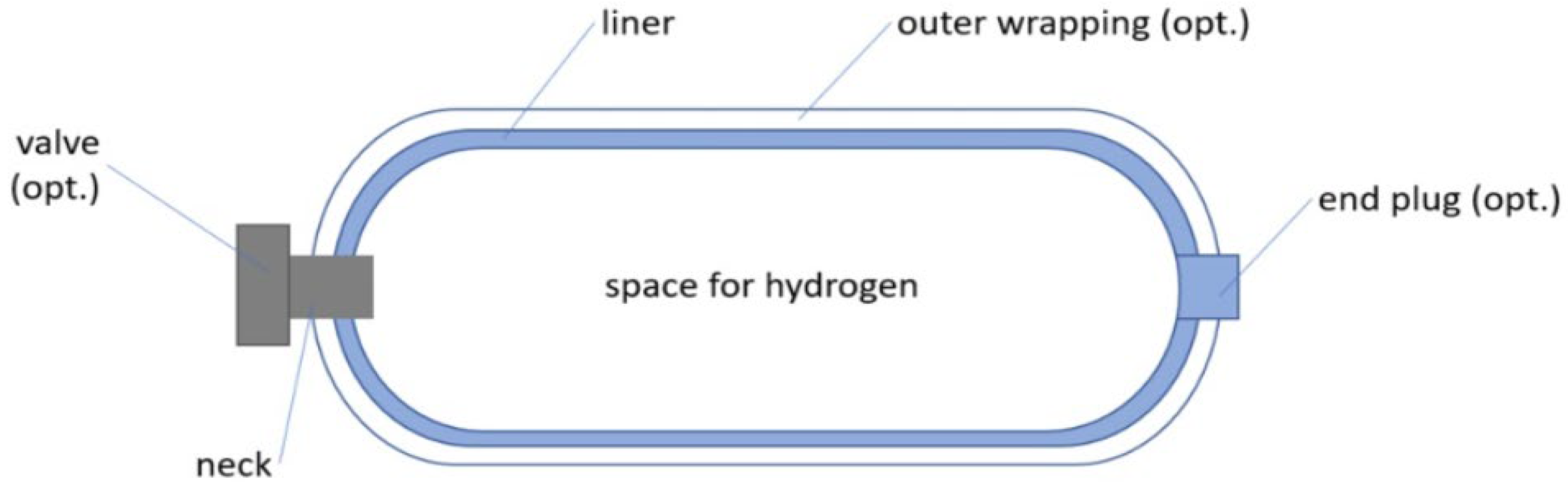
- A cylindrical tank was selected—composite cylinder of type 4, made by Hexagon Purus, pressure 700 bar and ambient temperature;
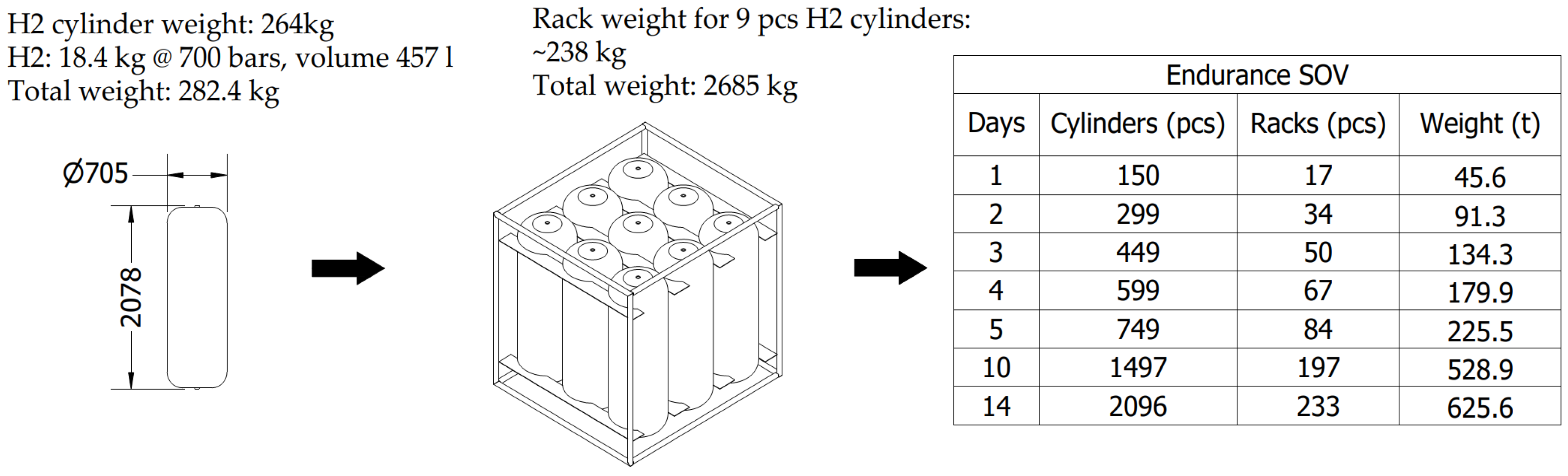
- Technical data—H2-70-705X2078:
- –
- Outside diameter DH2 = 705 mm;
- –
- Overall length LH2 = 2078 mm;
- –
- Cylinder weight WH2 = 264 kg;
- –
- Volume V = 457 litres;
- –
- Hydrogen capacity VH2 = 18.4 kg;
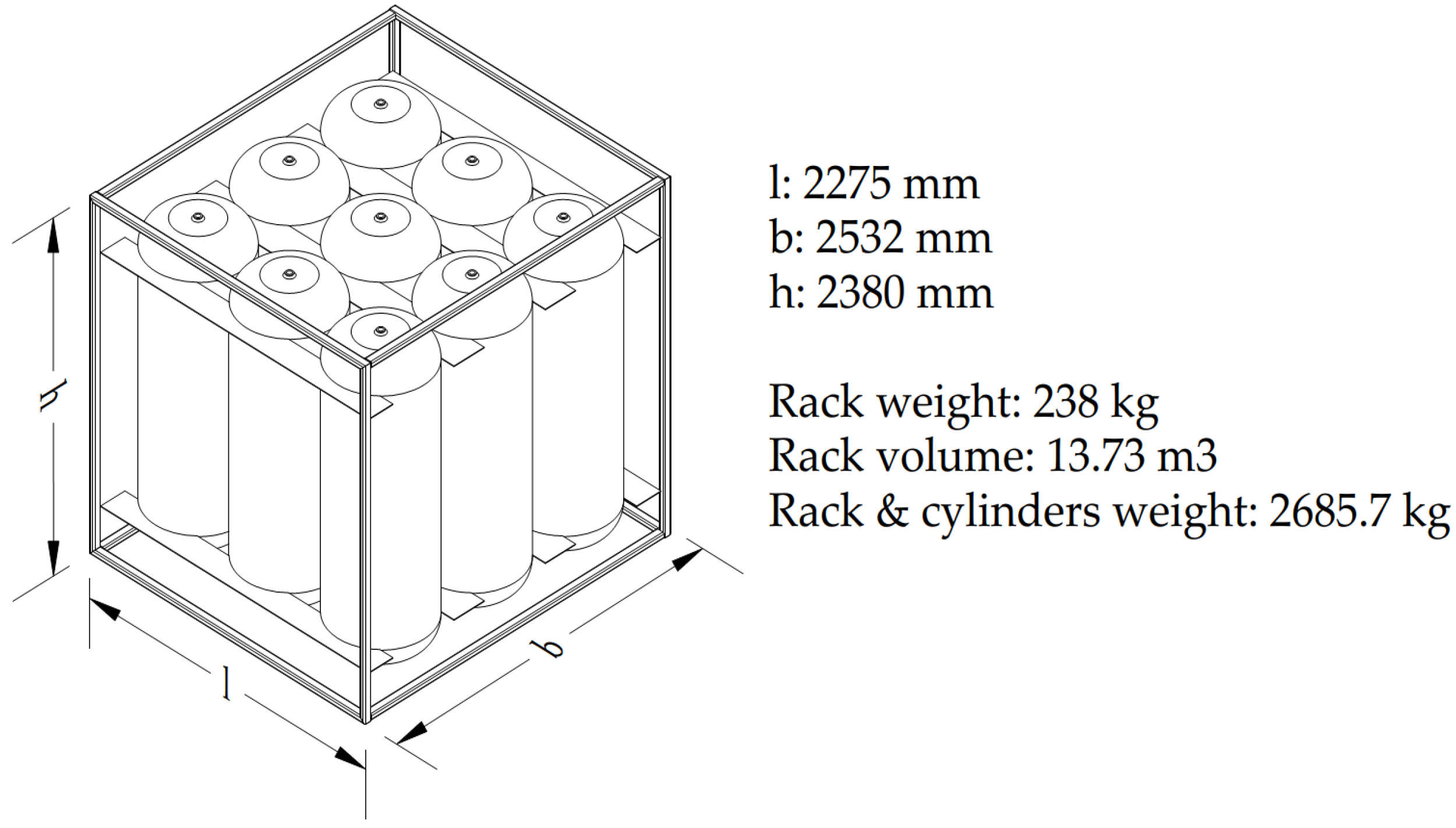
- Hydrogen fuel storage system on board the ship: the cylinders to be mounted on board in modular racks; each rack contains nine cylindrical cylinders, which can easily be combined; due to the limited manufacturer and regulatory guidelines on this issue, the authors chose the above concept as the preliminary one, which may be modified in the future.
2.3. Operational Profile of Service Vessel Work
- Normal operation: shipping to the working area;
- Service work in the offshore wind farms in the Baltic Sea;
- Normal operation: returning to port;
- Stopover in port.
- I—Operation with active working platform and DP2 dynamic positioning system (3.5 h);
- II—Manoeuvring (1.5 h);
- III—Operation with an inactive working platform and DP2 dynamic positioning system (3.5 h);
- IV—Low operation (1.0 h), vs = 6 knots;
- V—Night break using DP1 (14.5 h).
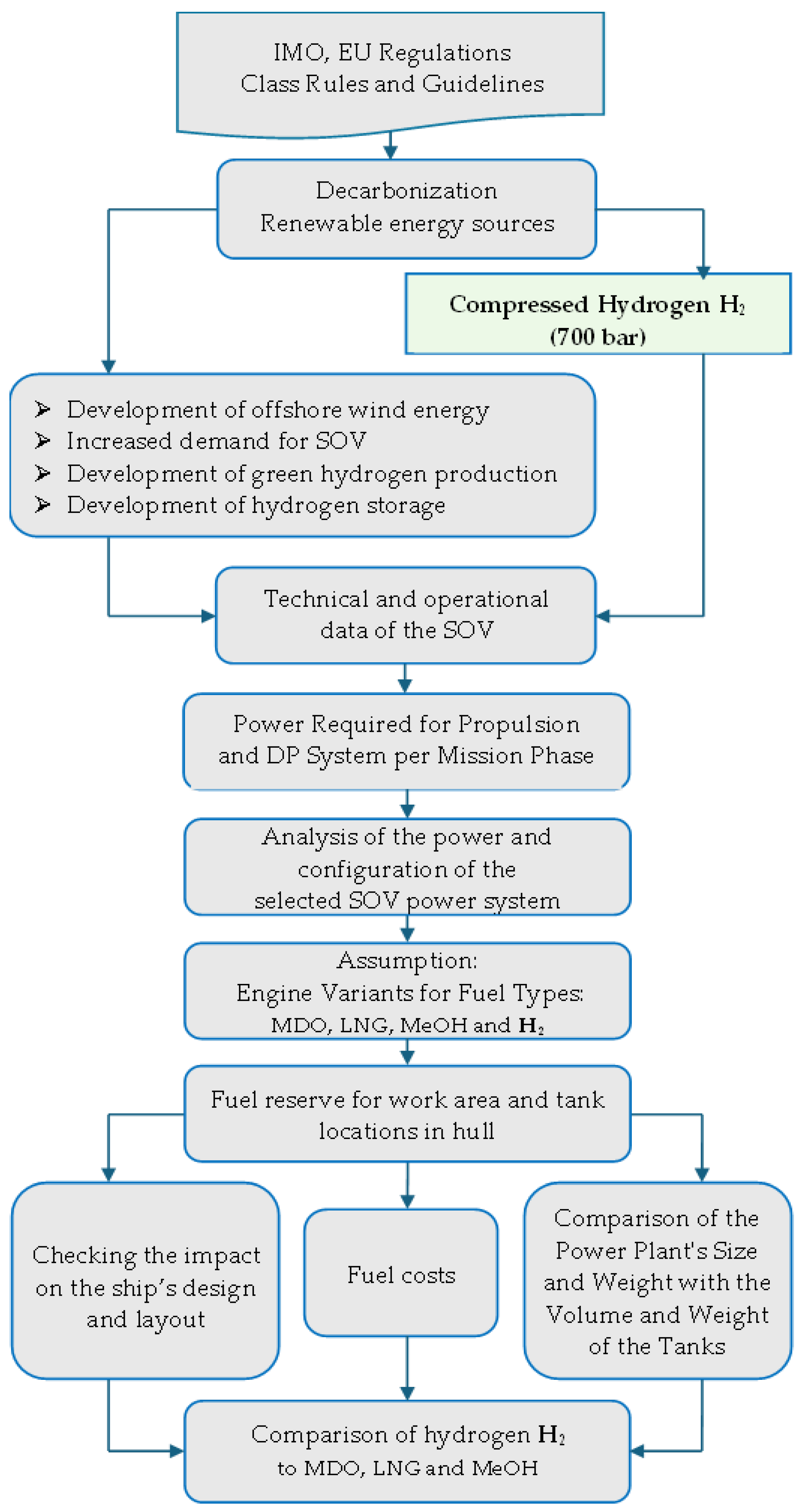
2.4. Research Method
- Technical and operational data of the service vessel analysed in previous work—acc. [52];
- Latest IMO guidelines relating to hydrogen fuel;
- Available engine solutions adapted to run on this new fuel;
- A storage system that allows hydrogen to be transported under high-pressure conditions.
3. Design Analysis of the SOV for the Use of Alternative Propulsion Fuels
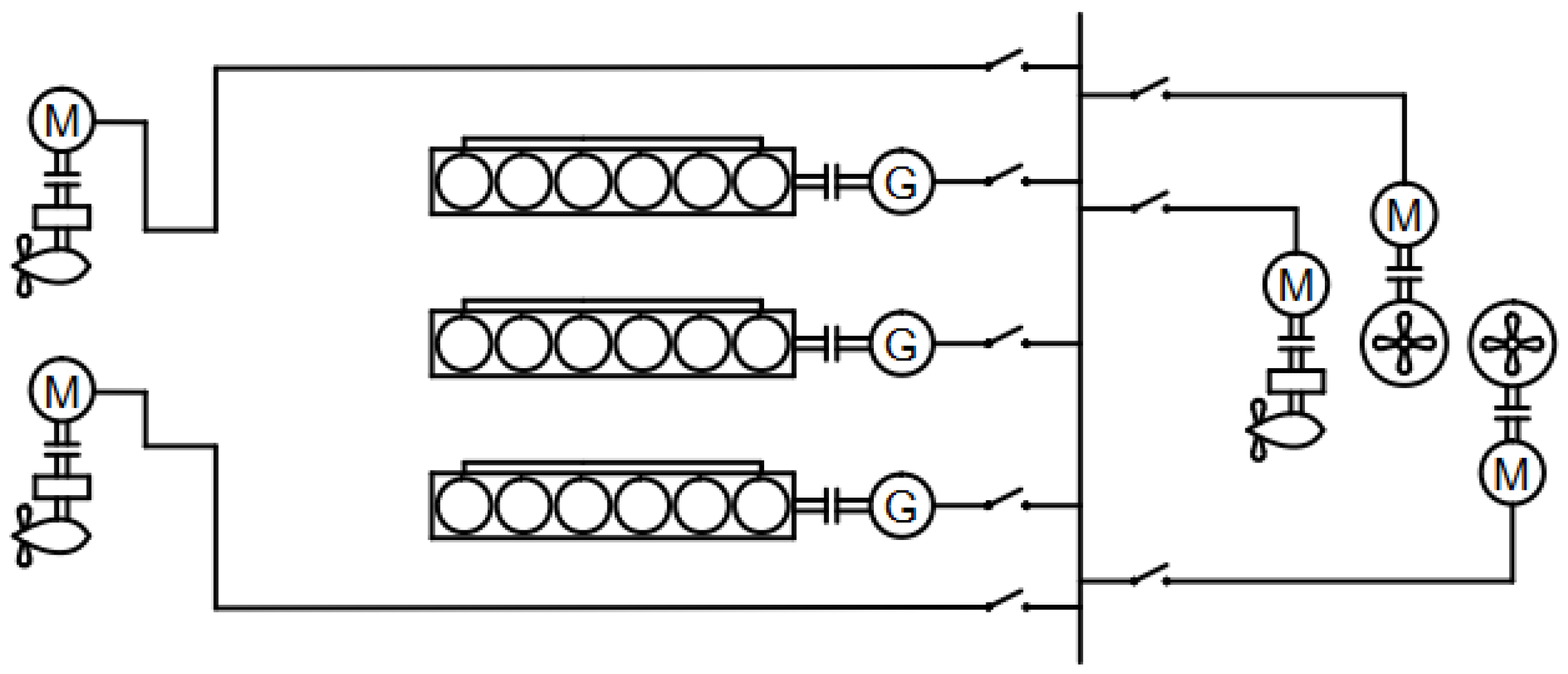
3.1. Selection of the Energy System Solution
3.1.1. Energy System Solutions for Service Offshore Vessels
3.1.2. DP2 Dynamic Positioning System
- (1)
- Maintain the position throughout the range of variations in hydrometeorological conditions specified in the design guidelines. This condition is met by installing generating sets and thrusters of sufficiently high power.
- (2)
- Maintain position even when a failure of any component occurs. This condition is met by adopting the redundancy concept, which is to maintain the dynamic positioning capability of the vessel in the event of a single failure of any component of the system.
3.1.3. Selection of Generating Sets
- Wärtsilä 20 (Wärtsilä Corporation, Helsinki, Finland) powered by conventional MDO fuel;
- Wärtsilä 20 dual-fuel (Wärtsilä Corporation, Helsinki, Finland) fed with LNG preceded by a pilot dose of conventional MDO fuel;
- Wärtsilä 20 (Wärtsilä Corporation, Helsinki, Finland) fuelled with methanol (M);
- BEH2YDRO DZD H2 (BeHydro, Gent, Belgium) fuelled with a mixture of hydrogen (H2) and MDO in a ratio of 85/15.
- Service space for generating set—500 mm;
- Distance needed to dismantle the pump cover with fitted pumps—650 mm;
- Width for dismantling lubricating oil module with lifting tool—approximately 500 mm.
3.1.4. Parameters of the Fuels Used
3.2. Technical Requirements for Fuel Tanks on Ships
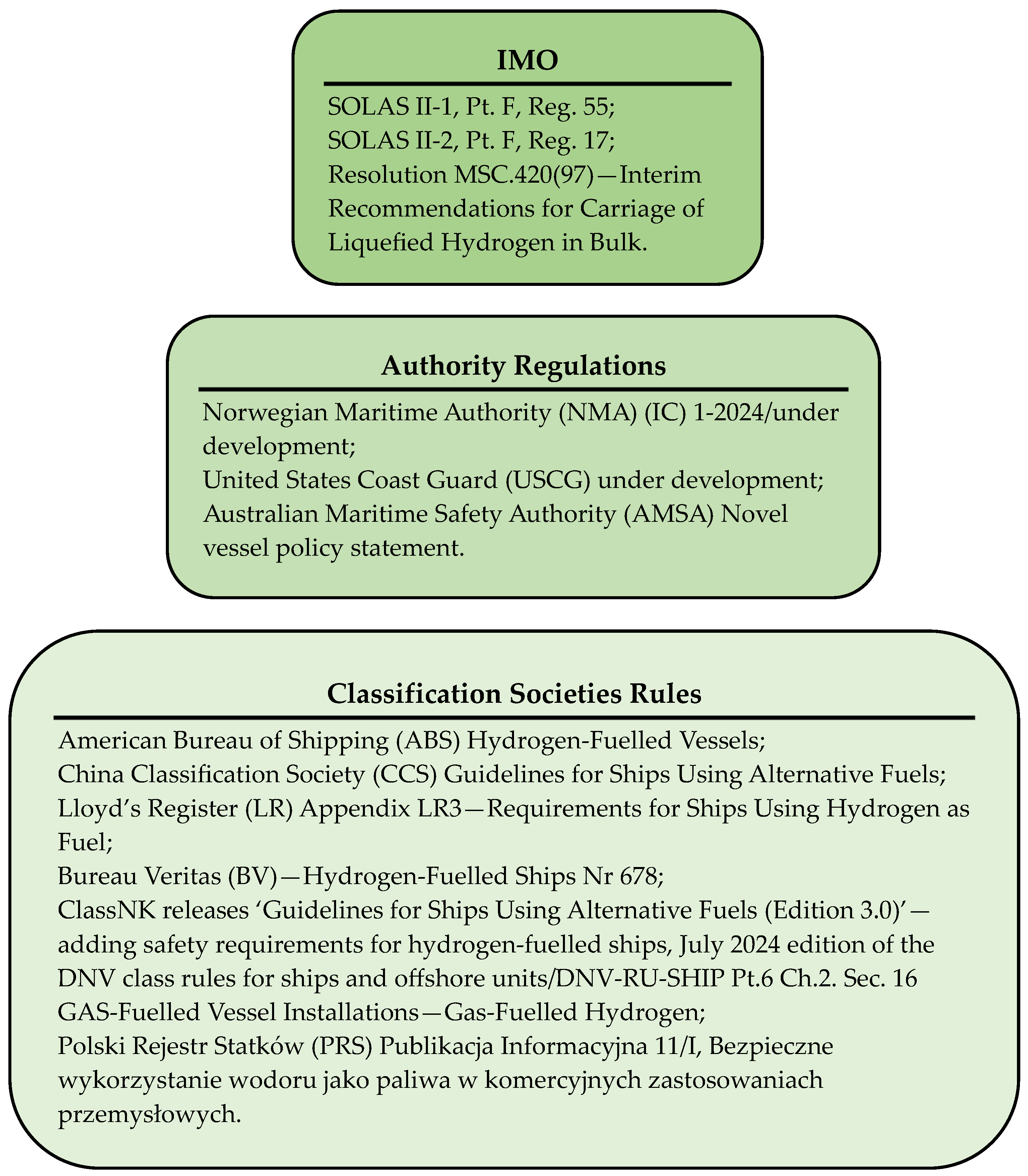
3.2.1. Current Regulations
3.2.2. Fuel Tanks with Compressed Hydrogen CH2 in the Ship’s Hull
- Use high-strength materials that are resistant to hydrogen permeability, hydrogen embrittlement and corrosion (this study uses composite containers with a lower weight and higher resistance to hydrogen diffusion compared to steel). Data on hydrogen embrittlement susceptibility of commonly used metallic materials are given in ISO/TR 15916: 2015, ANSI/AIAA G-095A-2017 or NASA TM-2016-218602;
- Locate the hydrogen fuel tanks in the ship’s hull and design the ship’s engine room along with the layout of other rooms containing the hydrogen fuel systems;
- Containers must be equipped with safety valves to discharge hydrogen in a controlled manner if the permitted pressure is exceeded (e.g., to the atmosphere via ventilation ducts);
- Hydrogen cylinders must be placed in separate technical rooms, away from heat sources (engines, boilers) and electrical equipment that could be a potential source of ignition;
- Tanks are to be separated from crew spaces by fire barriers (Class A-60);
- Tanks should be above the waterline (as high up in the hull as possible), and if not, very strict safety and access regulations must be met;
- Spaces where tanks are located must be equipped with ventilation systems with continuous air exchange to prevent the accumulation of hydrogen, which can be highly explosive, even at low concentrations, and equipped with hydrogen detector systems to detect its presence at very low concentrations and immediately raise an alarm if a leak is detected. The regulations require tanks to be located in open spaces or in enclosed spaces (equipped with an efficient ventilation system);
- Vessels inside the hull must be protected from mechanical damage, e.g., impacts or shocks, by additional protective covers or barriers;
- Bulkheads must be fire resistant and meet high fire insulation standards (Class A-60 according to IGF Code);
- Spaces with hydrogen tanks must be equipped with automatic fire detection systems and fixed fire extinguishing systems, i.e., water spray or powder extinguishing systems or gas extinguishing systems.
3.3. Calculation of Fuel Supply and Arrangement of Tanks in the Ship’s Hull
3.3.1. Estimation of Fuel Quantity
- Fuel consumption per hour Gfuel [kg/h]:where PR—rated power [kW], LHV—emergency content [kJ/kg], and ηDE—engine efficiency [-];
- Total fuel reserve MTfuel [t]:where Gfuel—the fuel consumption per hour [kg/h], and TS—mission duration [h];
- Fuel volume Vfuel [m3]:where MTfuel—total fuel reserve [t], and ρfuel—fuel density [kg/m3];
- Specific fuel consumption gfuel [g/kWh]:where Gfuel—the fuel consumption per hour [kg/h], and PR—rated power [kW].
3.3.2. Load Factor Analysis of Reciprocating Internal Combustion Engines
- Engine load Eload [%]:where PR′—power requirement [kW], and PR—rated power [kW].
- The 8 DZD H2 with a power of 1200 kW;
- The 12 DZD H2 with a power of 1800 kW;
- The 16 DZD H2 with a power of 2400 kW.
3.3.3. Hydrogen Fuel Volume and Arrangement of Cylinders in the Ship’s Hull
- Reducing the service life of the vessel;
- Creating opportunities for offshore hydrogen refuelling, e.g., at an offshore hydrogen plant, which could ultimately be connected to an offshore wind farm;
- Employing an additional battery system for electricity storage;
- Replacing gensets with reciprocating internal combustion engine generators by hydrogen fuel cells supported by an electricity storage system.
3.4. Fuel Costs
- PMDO = 650.50 [USD/mt]—the unit price of MDO;
- PLNG = 806 [USD/mt]—the unit price of LNG;
- Pmethanol = 454 [USD/mt]—the unit price of methanol;
- PH2 = 3.80–9.40 [EUR/kg]—the unit price of hydrogen (at an average exchange rate of EUR 1 = USD 1.05, PH2 = 3990–9870 [USD/mt]).
- Fuel costs [USD/mission]:where MTfuel—total fuel reserve [mt], and Pfuel—fuel unit price (depending on the type of fuel assumed) [USD/mt];
- Number of voyages per year [-]:where TR—operating days [day], and TS—mission duration [day];
- Annual fuel costs [USD/year]:where nM—number of voyages per year [-], and Kfuel—fuel costs [USD/mission].
4. Results
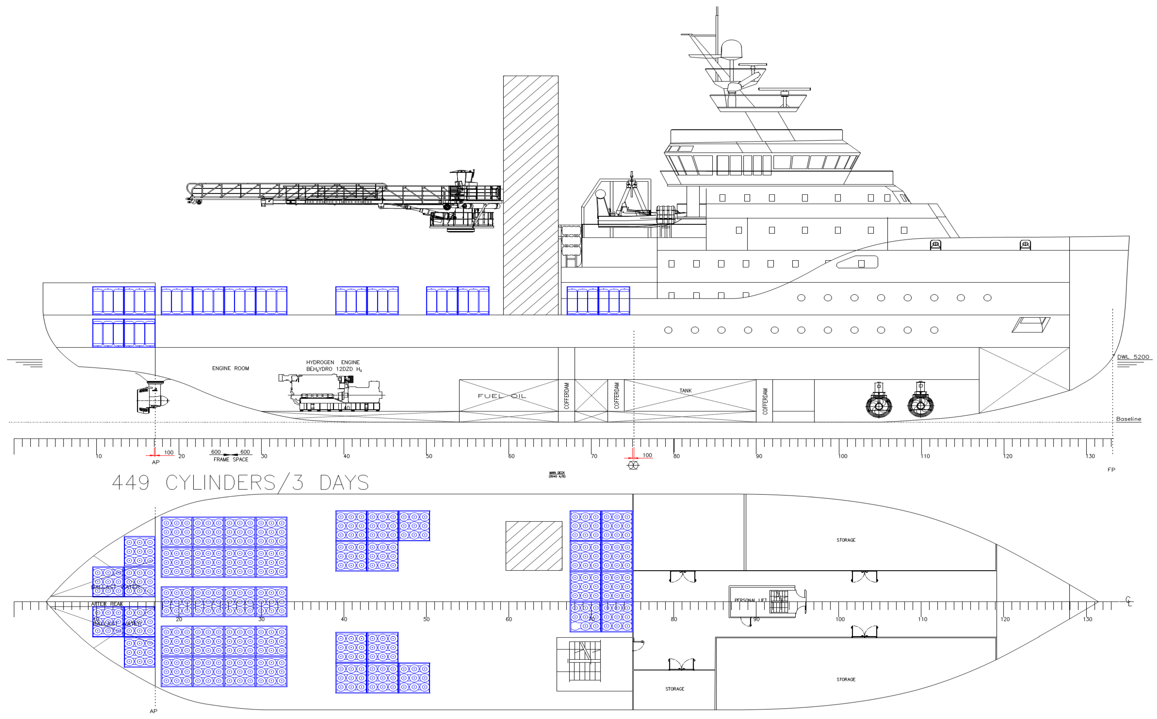
4.1. Arrangement of Hydrogen Cylinders on the SOV
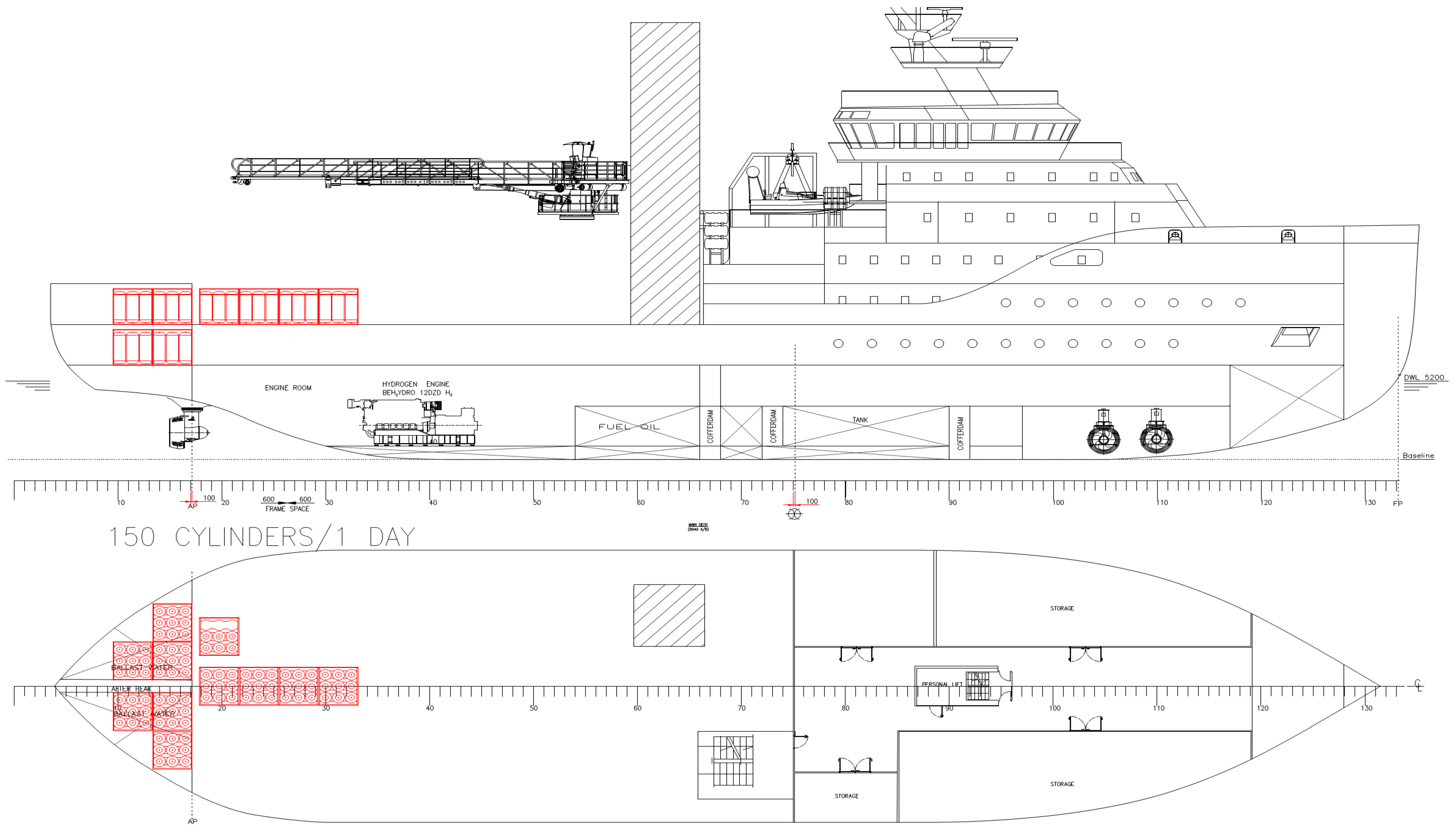
- Variant 1—150 cylinders deployed in 17 modules (red)—the case for a one-day mission. This option was considered a good reference for other cases considered;
- Variant 2—deployment of 449 cylinders in 50 modules (blue)—for a 3-day ship mission—the most likely and feasible option:
- –
- Total fuel reserve MTfuel—9.1 t;
- –
- Fuel volume Vfuel—205.75 m3;
- –
- Full cylinder weight (with hydrogen)—134.3 t.
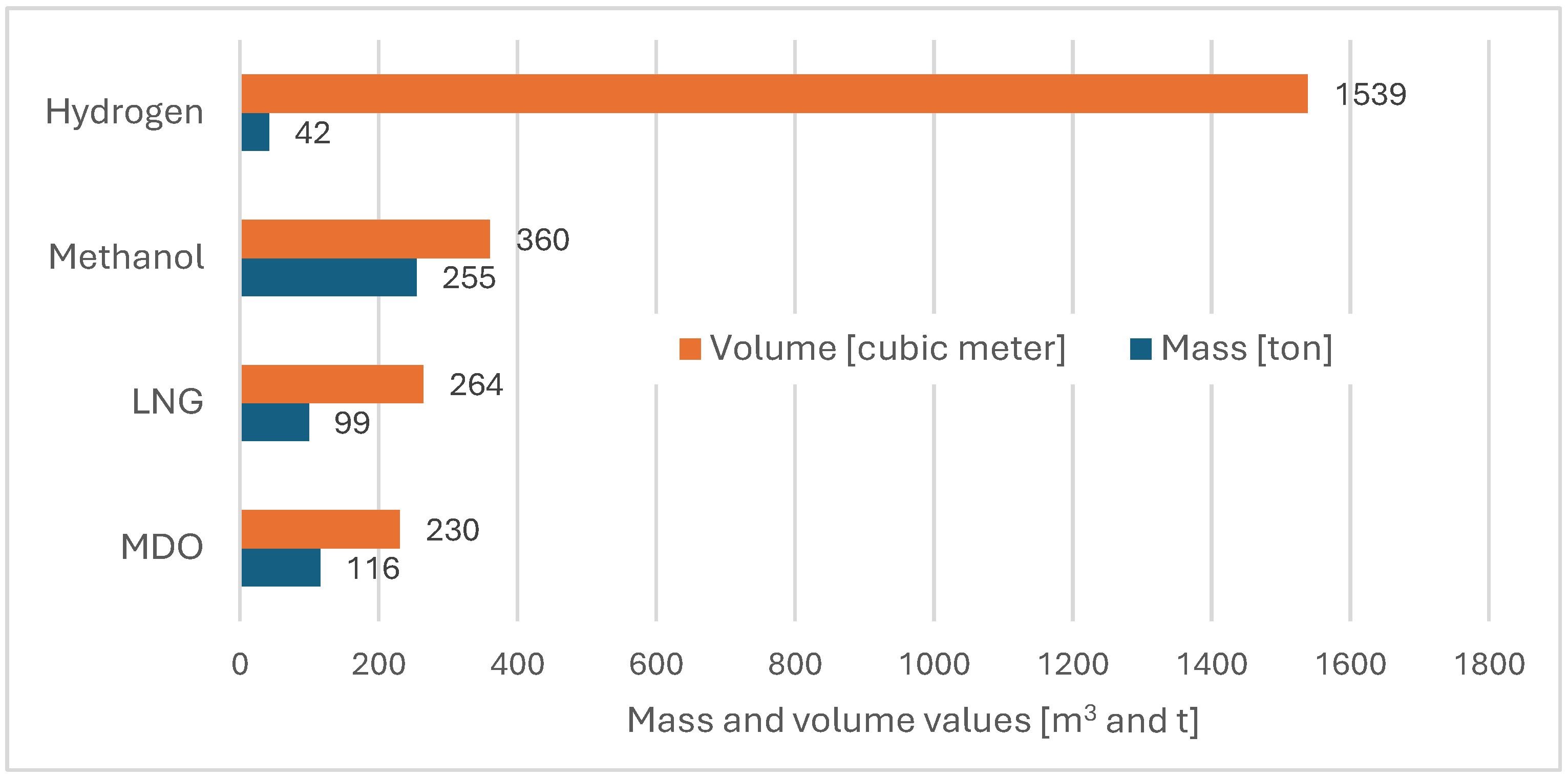
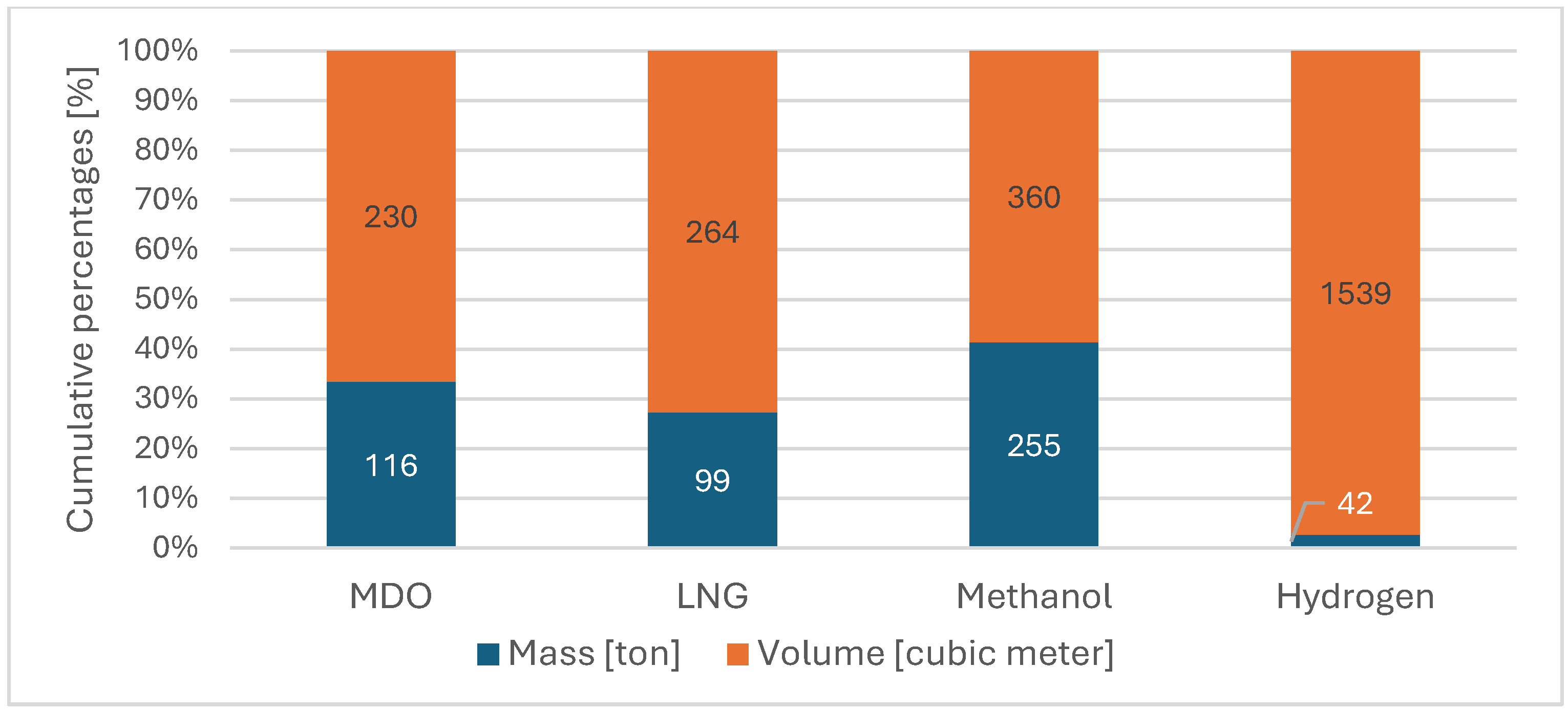
4.2. Needed Masses and Volumes of Hydrogen
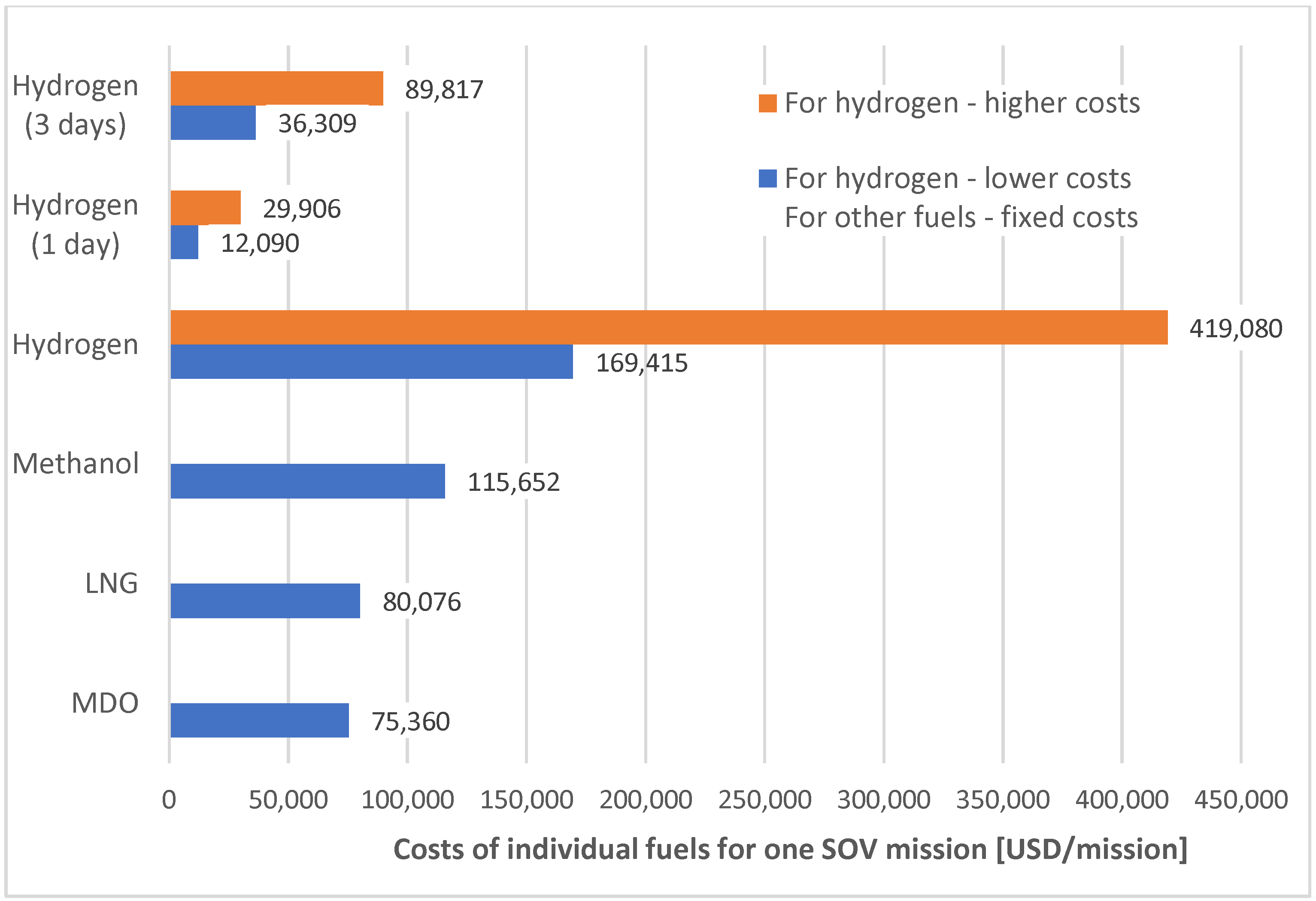
4.3. Calculated Fuel Costs
5. Summary and Conclusions
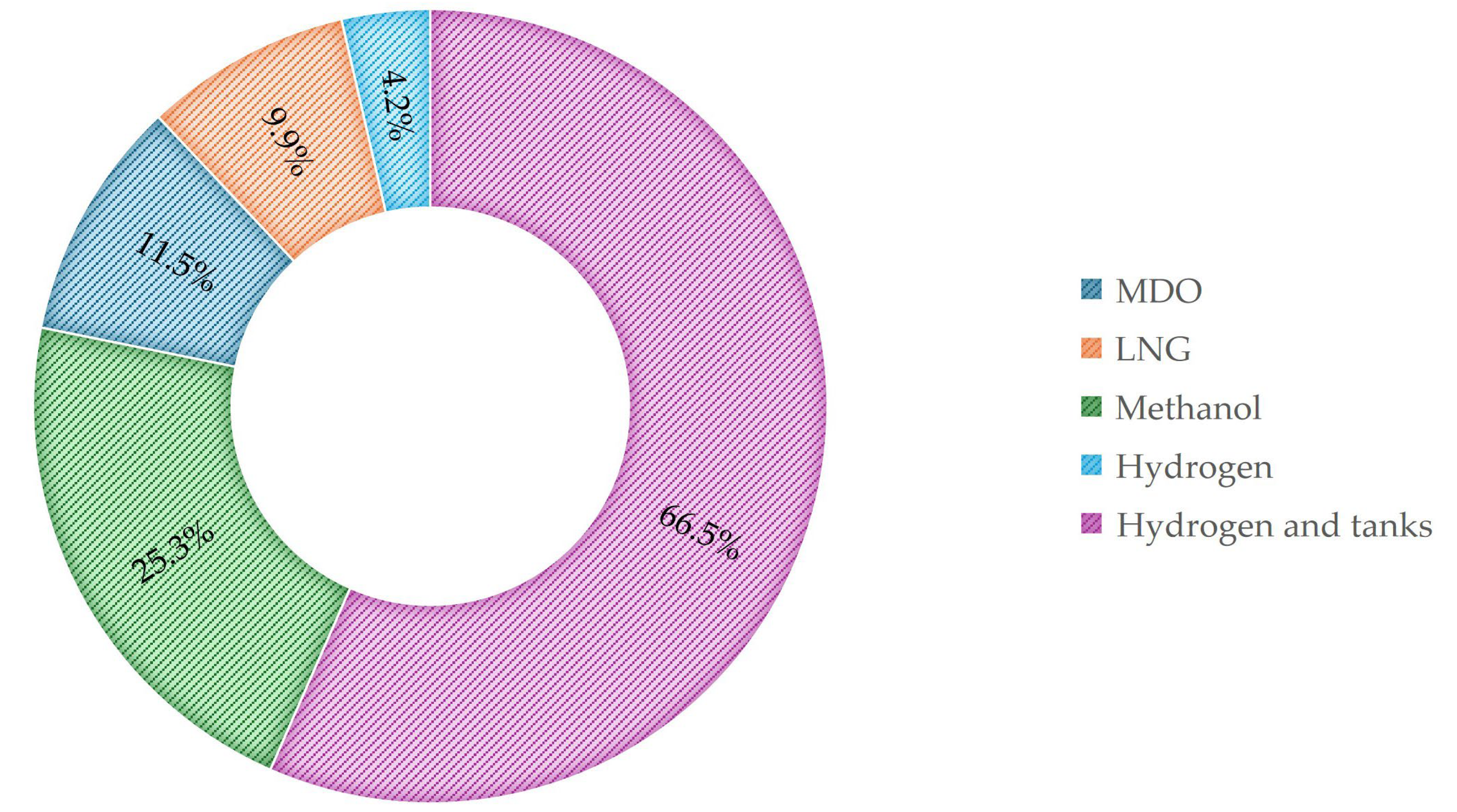
- The weight of the hydrogen tanks and the modular system amounted to about 626 t, which is 62% of the ship’s current carrying capacity;
- The volume of the hydrogen tanks and the modular system occupies 3198 m3, which is 66% of the ship’s current volume.
- More than 100% higher than MDO and LNG;
- More than 30% higher than MeOH.
- The analysis of the configuration of the generating sets should be carried out very carefully, as it affects the change in the required hydrogen in stores and may cause problems in the spatial layout of the power plant.
- The use of compressed hydrogen as fuel on the SOV is possible and has a significant impact on the design of structural elements and spatial layout of the vessel; however, in order to fully exploit the potential of hydrogen, several important problems need to be solved related to hydrogen generation and storage and ship refuelling in offshore areas, such as offshore wind farms.
- In order to increase the economic viability of operating a hydrogen-powered SOV using reciprocating internal combustion engines in its energy system, hydrogen prices must go down, especially the ‘green’ variety. With moderate hydrogen prices, the operation of such a vessel will be viable, especially when we appreciate zero CO2 emissions.
Author Contributions
Funding
Data Availability Statement
Conflicts of Interest
References
- International Maritime Organization (IMO). Available online: https://www.imo.org/ (accessed on 10 October 2024).
- Review of Maritime Transport 2023. UN Trade and Development. Available online: https://unctad.org/publication/review-maritime-transport-2023 (accessed on 10 October 2024).
- Ørbeck-Nilssen, K. CEO Maritime DNV. A Deep Dive into Shipping’s Decarbonization Journey. Energy Transition Outlook 2023, Maritime Forecast to 2050. Available online: https://www.dnv.com/publications/maritime-forecast-to-2050-edition-2023/ (accessed on 10 October 2024).
- International Energy Agency. Global Hydrogen Review 2024. Revised Version October 2024. Available online: https://www.iea.org/reports/global-hydrogen-review-2024 (accessed on 10 October 2024).
- Maritime Forecast to 2050, Report DNV. Available online: https://www.dnv.com/maritime/publications/maritime-forecast (accessed on 10 October 2024).
- Mandra, J.O. Clarksons: 45% of Ships Ordered in 2023 Embrace Alternative Fuels, with LNG Still in the Lead. Business Developments & Projects. 3 January 2024. Available online: https://www.offshore-energy.biz/clarksons-45-of-ships-ordered-in-2023-embrace-alternative-fuels-with-lng-still-in-the-lead/ (accessed on 10 October 2024).
- Potential of Hydrogen as Fuel for Shipping by ABS, CE DELFT & ARCSILEA, European Maritime Safety Agency EMSA/Hydrogen—2022/2023—4837444. 31 August 2023. Available online: https://emsa.europa.eu/publications/reports/item/5062-potential-of-hydrogen-as-fuel-for-shipping.html (accessed on 10 October 2024).
- E-Magazyny. Available online: https://e-magazyny.pl/aktualnosci/elektromobilnosc/usa-pierwszy-statek-na-wodor-sea-change/ (accessed on 3 June 2024).
- Switch Maritime. Available online: https://www.switchmaritime.com (accessed on 1 August 2024).
- Ship Technology. Available online: https://www.ship-technology.com/projects/hydroville-passenger-ferry/?cf-view&cf-closed (accessed on 1 August 2024).
- Ostvik, I. MF Hydrs—World’s First LH2 Driven Ship and He Challenges Ahead Towards Zero-Emission Shipping. NORLED, The Greatest Travel Experiences. 2021. Available online: https://www.uib.no/sites/w3.uib.no/files/attachments/norled_mf_hydra_dec_2021.pdf (accessed on 23 August 2024).
- Berger, M. Statki Napędzane Wodorem. Tak, to Tylko Kwestia Czasu. Bezemisyjny Transport Wodny. Available online: https://elektromobilni.pl/statki-napedzane-wodorem-tak-to-tylko-kwestia-czasu (accessed on 8 September 2024).
- Grzybowski, M. The Hydrogen SOV Is Sailing Out into the Open Waters. BSSC. 2024. Available online: https://www.bssc.pl/2024/05/16/the-hydrogen-sov-is-sailing-out-into-the-open-waters/ (accessed on 24 September 2024).
- Offshore WIND. Available online: https://www.offshorewind.biz/2024/03/19/louis-dreyfus-armateurs-unveils-liquid-hydrogen-sov-concept/ (accessed on 24 September 2024).
- Melideo, D.; Desideri, U. The use of hydrogen as alternative fuel for ship propulsion: A case study of full and partial retrofitting of roll-on/roll-off vessels for short distance routes. Int. J. Hydrogen Energy 2024, 50, 1045–1055. [Google Scholar] [CrossRef]
- Liu, X.; Yang, G.; Sun, B.; Wang, H.; Li, Y.; Wang, R. Assist in GHG Abatement of Offshore Ships: Design and Economic Analysis of an Integrated Utilization Model of hydrogen-powered Ship and Offshore Wind Power. Sustain. Mar. Struct. 2023, 5, 15–25. [Google Scholar] [CrossRef]
- Kołodziejski, M. Review of hydrogen-based propulsion systems in the maritime sector. Arch. Thermodyn. 2024, 44, 335–380. [Google Scholar] [CrossRef]
- Karvounis, P.; Tsoumpris, C.; Boulougouris, E.; Theotokatos, G. Recent advances in sustainable and safe marine engine operation with alternative fuels. Front. Mech. Eng. 2022, 8, 994942. [Google Scholar] [CrossRef]
- Minutillo, M.; Cigolotti, V.; Di Ilio, G.; Bionda, A.; Boonen, E.J.; Wannemacher, T. Hydrogen-based technologies in maritime sector: Technical analysis and prospective. In Proceedings of the European Fuel Cells and Hydrogen Piero Lunghi Conference, Online, 15–17 December 2021; Volume 334, p. 06011. [Google Scholar]
- Lee, G.; Kim, J.M.; Yung, K.H.; Park, H.; Jang, H.; Lee, C.S.; Lee, J.W. Environmental Life-Cycle Assessment of Eco-Friendly Alternative Ship Fuels (MGO, LNG, and Hydrogen) for 170 GT Nearshore Ferry. J. Mar. Sci. Eng. 2022, 10, 755. [Google Scholar] [CrossRef]
- Perčić, M.; Vladimir, N.; Koričan, M.; Jovanović, I.; Haramina, T. Alternative Fuels for the Marine Sector and Their Applicability for Purse Seiners in a Life-Cycle Framework. Appl. Sci. 2023, 13, 13068. [Google Scholar] [CrossRef]
- Krantz, G.; Moretti, C.; Brandão, M.; Hedenqvist, M.S.; Nilsson, F. Assessing the Environmental Impact of Eight Alternative Fuels in International Shipping: A Comparison of Marginal vs. Average Emissions. Environments 2023, 10, 155. [Google Scholar] [CrossRef]
- Wang, Q.; Zhang, H.; Huang, J.; Zhang, P. The use of alternative fuels for maritime decarbonization. Special marine environmental risks and solutions from an international law perspective. Front. Mar. Sci. 2023, 9, 1082453. [Google Scholar] [CrossRef]
- dos Santos, V.A.; da Silva, P.P.; Serrano, L. The Maritime Sector and Its Problematic Decarbonization: A Systematic Review of the Contribution of Alternative Fuels. Energies 2022, 15, 3571. [Google Scholar] [CrossRef]
- McKenney, T.A. The impact of maritime decarbonization on ship design: State-of-the-Art Report. In Proceedings of the 15th International Marine Design Conference (IMDC-2024), Delft, The Netherlands, 2–6 June 2024; Available online: https://www.researchgate.net/publication/380892629_The_impact_of_maritime_decarbonization_on_ship_design_State-of-the-Art_Report (accessed on 10 September 2024).
- Bacquart, T.; Moore, N.; Wilmot, R.; Bartlett, S.; Morris, A.S.O.; Olden, J.; Becker, H.; Aarhaug, T.A.; Germe, S.; Riot, P.; et al. Hydrogen for Maritime Application—Quality of Hydrogen Generated Onboard Ship by Electrolysis of Purified Seawater. Processes 2021, 9, 1252. [Google Scholar] [CrossRef]
- Hwang, S.S.; Gil, S.J.; Lee, G.N.; Lee, J.W.; Park, H.; Jung, K.H.; Suh, S.B. Life cycle assessment of alternative ship fuels for coastal ferry operating in Republic of Korea. J. Mar. Sci. Eng. 2020, 8, 660. [Google Scholar] [CrossRef]
- Dong, D.; Schönborn, A.; Christodoulou, A.; Ölçer, A.; González-Celis, J. Life cycle assessment of ammonia/hydrogen-driven marine propulsion. Proc. Inst. Mech. Eng. Part M J. Eng. Marit. Environ. 2024, 238, 531–542. [Google Scholar] [CrossRef]
- Panić, I.; Cuculić, A.; Ćelić, J. Color-coded hydrogen: Production and storage in maritime sector. J. Mar. Sci. Eng. 2022, 10, 1995. [Google Scholar] [CrossRef]
- Zintegrowana Platforma Edukacyjna Ministerstwa Edukacji Narodowej. Available online: https://zpe.gov.pl/a/wo-dor/DbFQCGctg (accessed on 10 October 2024).
- Publikacja Informacyjna PRS 11/I. Bezpieczne Wykorzystanie Wodoru Jako Paliwa w Komercyjnych Zastosowaniach Przemysłowych. PRS. Czerwiec 2021. Available online: https://prs.pl/wp-content/uploads/2024/03/p11i_pl.pdf (accessed on 7 July 2024).
- Züttel, A. Materials for hydrogen storage. Mater. Today 2003, 6, 24–33. [Google Scholar] [CrossRef]
- Ligęza, K.; Narloch, P. Perspektywy magazynowania wodoru z odnawialnych źródeł energii w Polsce cz. 1. Nowa Energ. 2023, 1, 73–81. [Google Scholar]
- Zuttel, A.; Borgschulte, A.; Schlapbach, L. Hydrogen as a Future Energy Carrier; Wiley-VCH Verlag GmbH & Co. KGaA: Weinheim, Germany, 2008. [Google Scholar]
- Kozikowski, S.; Szymlek, K. Wodór—Zielone Złoto Bezpieczne Magazynowanie—Szanse i Wyzwania. Innowacje w Energetyce 2022. Available online: https://www.cire.pl/filemanager/Materia%C5%82y%20Problemowe%20(Wies%C5%82aw%20Drozdowski)%20/046366fa71c120f78917931799e8aae2abc9495995753756f4091b2bf5a3d369.pdf (accessed on 17 September 2024).
- CW Composites World. Available online: https://www.compositesworld.com/articles/infinite-composites-type-v-tanks-for-space-hydrogen-automotive-and-more (accessed on 17 September 2024).
- Hyfindr. Available online: https://hyfindr.com/en/hydrogen-knowledge/hydrogen-tank (accessed on 17 September 2024).
- Rynek Zbiorników Ciśnieniowych—Materiały Kompozytowe—Composite Marerials (kompozyty.net). Available online: https://kompozyty.net/rynek-zbiornikow-cisnieniowych/ (accessed on 24 September 2024).
- Magazynowanie Wodoru. Available online: https://wme-z1.pwr.edu.pl/wp-content/uploads/2020/01/3-Magazynowanie-wodoru-2019.pdf (accessed on 24 September 2024).
- Amargo Tank Think Tank. Available online: https://www.amargo.pl/zbiorniki-kompozytowe-do-magazynowania-wodoru-typ-iv-potencjal-projektu-i-aktualny-poziom-gotowosci-technologicznej/ (accessed on 24 September 2024).
- Hexagon Purus. Type-4-Infrastructure-and-Mobility-Hexagon-Purus-Datasheet.pdf. Rev. 04/2024. Available online: https://hexagonpurus.com/our-solutions/download-our-brochures/datasheets (accessed on 17 September 2024).
- NPROXX. Available online: https://www.nproxx.com/hydrogen-powered-heavy-duty-vehicles/shipping-maritime/ (accessed on 17 September 2024).
- NPROXX. Available online: https://www.nproxx.com/nproxx-introduces-the-new-700-bar-hydrogen-pressure-vessel-ah620-70-2-targeting-heavy-vehicles-long-haul-trucks-and-the-automotive-sector/ (accessed on 17 September 2024).
- Szwaja, S. Wodór Jako Paliwo Podstawowe i Dodatkowe do Tłokowego Silnika Spalinowego; Wydawnictwo Politechniki Częstochowskiej: Częstochowa, Poland, 2019. [Google Scholar]
- Katalog Firmy MAN. Hydrogen in Shipping; MAN Energy Solutions: Augsburg, Germany, 2020. [Google Scholar]
- Portal Internetowy Firmy Wärtsilä—The World’s First Large-Scale Hydrogen Engine Power Plant Is Here. Available online: https://www.wartsila.com/energy/sustainable-fuels/hydrogen-power-plant (accessed on 25 September 2024).
- Portal WinGD. WinGD and Hyundai Heavy Industries Collaborate on Ammonia Two-Stroke Engine Delivery. 2022. Available online: https://www.wingd.com/en/news-media/press-releases/wingd-and-hyundai-heavy-industries-collaborate-on-ammonia-two-stroke-engine-delivery/ (accessed on 25 September 2024).
- Katalog Silników BEH2YDRO. “Datasheet DZD H2”. Anglo Belgian Corporation. 2022. Available online: https://www.behydro.com/uploads/files/DATASHEETS-Behydro.pdf (accessed on 25 September 2024).
- Katalog Zastosowania Silników BEH2YDRO “Information Sheet”; Anglo Belgian Corporation: Gent, Belgium, 2022.
- Wynalazcy z Politechniki Przystosowali Silnik Spalinowy do Zasilania Wodorem; Politechnika Krakowska: Kraków, Poland, 2024; Available online: https://www.pk.edu.pl/index.php?option=com_content&view=article&id=5193&Ite-mid=1152&lang=pl (accessed on 25 September 2024).
- Katalog Silnika Scania: Scania Marine Engines DI09 074M. Scania CV AB. 2022. Available online: https://www.scania.com/content/dam/scanianoe/market/master/products-and-services/engines/pdf/specs/marine/DI09074M_269kW.pdf (accessed on 25 September 2024).
- Bortnowska, M. Projected Reductions in CO2 Emissions by Using Alternative Methanol Fuel to Power a Service Operation Vessel. Energies 2023, 16, 7419. [Google Scholar] [CrossRef]
- Oleksiuk, J. Projekt Koncepcyjny Statku SOV do Obsługi Farm Wiatrowych. Master’s Thesis, Faculty of Navigation, Maritime University in Szczecin, Szczecin, Poland, 2023. [Google Scholar]
- Cichocki, M. Napędy Statków Dynamicznie Pozycjonowanych: Aspekty Eksploatacyjne; Wydawnictwo Naukowe PWN: Warszawa, Poland, 2018. [Google Scholar]
- Clark, I.C.; Hancox, M. Anchor Handling Tug Operations; The ABR Company Limited: Trowbridge, UK, 2012. [Google Scholar]
- Katalog Silników. Wärtsilä 20—Product Guide; Wärtsilä Corporation: Helsinki, Finland, 2020. [Google Scholar]
- Katalog Silników. Wärtsilä 20; Wärtsilä Corporation: Helsinki, Finland, 2024. [Google Scholar]
- Katalog Silników. Wärtsilä Methanol Engines—The Power to Achieve Carbon Neutrality; Wärtsilä Corporation: Helsinki, Finland, 2023. [Google Scholar]
- Katalog Silników. Wärtsilä 20DF; Wärtsilä Corporation: Helsinki, Finland, 2023. [Google Scholar]
- Giernalczyk, M.; Górski, Z. Siłownie Okrętowe—Część II: Instalacje Okrętowe; Wydawnictwo Akademii Morskiej w Gdyni: Gdynia, Poland, 2014. [Google Scholar]
- Nasser, M.A.; Elgohary, M.M.; Abdelnaby, M.; Shouman, M.R. Environmental and economic performance investigation of natural gas and methanol as a marine alternative fuel. Res. Sq. 2022. Available online: https://www.researchgate.net/publication/363371092_Environmental_and_economic_performance_investigation_of_natral_gas_and_-methanol_as_a_marine_alternative_fuel (accessed on 14 September 2024).
- Methanol Safe Handling Technical Bulletin—Part 1—B: Physical & Chemical Properties of Selected Fuels (1). Methanol Institute. Available online: https://www.methanol.org/wp-content/uploads/2020/04/Part-1-B_-Physical-Chemical-Properties-of-Selected-Fuels-.pdf (accessed on 14 September 2024).
- The Methanol—Fuelled MAN B&W LGIM Engine. MAN Energy Solutions. Available online: https://www.man-es.com/docs/default-source/document-sync-archive/the-methanol-fuelled-man-b-w-lgim-engine-eng.pdf?sfvrsn=36b925d2_7 (accessed on 14 September 2024).
- International Maritime Organization (IMO). MSC.1/Circ.1212/Rev.2. 2024. Available online: https://www.skanregistry.com/uploads/download-directory/pdf/357/document.pdf (accessed on 12 October 2024).
- Hellenic Shipping News. Available online: https://www.hellenicshippingnews.com/imo-ccc-10-interim-guidelines-for-ammonia-and-hydrogen-as-fuel/ (accessed on 12 October 2024).
- International Maritime Organization (IMO). Available online: https://www.imo.org/en/OurWork/Safety/Pages/IGF-Code.aspx (accessed on 12 October 2024).
- International Maritime Organization (IMO). Available online: https://www.imo.org/en/MediaCentre/Pages/WhatsNew-1392 (accessed on 12 October 2024).
- Piotrowski, I.; Witkowski, K. Okrętowe Silniki Spalinowe; Trademar: Gdynia, Poland, 2013. [Google Scholar]
- Katalog Silników. Dual-Fuel Engines—WÄRTSILÄ 20DF, 34DF, 46DF and 50DF; Wärtsilä Corporation: Helsinki, Finland, 2015. [Google Scholar]
- Gómez, J.; Castro, R. Green Hydrogen Energy Systems: A Review on Their Contribution to a Renewable Energy System, Energy System. Energies 2024, 17, 3110. [Google Scholar] [CrossRef]
- Ship & Bunker. Available online: https://shipandbunker.com/prices/emea/nwe/nl-rtm-rotterdam (accessed on 10 October 2024).

| Reference | Outside Diameter [mm] | Overall Length [mm] | Cylinder Weight [kg] | Water Volume [L] | Hydrogen Capacity [kg] | Weight Ratio (Hydrogen Weight/Cylinder Weight) [%] |
|---|---|---|---|---|---|---|
| H2-70-440X1050 | 440 | 1050 | 59 | 76 | 3.1 | 5.3 |
| H2-70-530X2154 | 530 | 2154 | 188 | 244 | 9.8 | 5.2 |
| H2-70-610X2060 | 600 | 2060 | 208 | 360 | 14.5 | 7.0 |
| H2-70-705X2078 | 705 | 2078 | 264 | 458 | 18.4 | 7.0 |
| Parameter | Specifications | |
|---|---|---|
| AH 710-70 | AH 620-70 | |
| Volume [L] | 553 | 350 |
| Weight [kg] | 338 | 211 |
| Usable H2 mass [kg] | 22.2 | 12.4 |
| Outer diameter [mm] | 700 | 610 |
| Length incl. valve [mm] | 2454 | 1917 |
| Mounting | Neck mounting | Neck mounting |
| Weight ratio (hydrogen weight/cylinder weight) [%] | 6.6 | 5.9 |
| No. | Parameter | Value | Symbol | Unit |
|---|---|---|---|---|
| 1. | Length between perpendiculars | 72.0 | Lbp | m |
| 2. | Breadth | 18.0 | B | m |
| 3. | Hull depth | 8.9 | H | m |
| 4. | Draught | 5.3 | T | m |
| 5. | Displacement | 5004 | D | t |
| 6. | Deadweight | 1005 | DWT | t |
| 7. | Cargo weather deck area | 280 | Awd | m2 |
| 8. | Technical crew number | 60 | n | people |
| 9. | Dynamic positioning system | - | DP2 | - |
| 10. | Endurance | 14 | A | days |
| Service Work Phases | Power Requirement PR′ [kW] ** | Time T [h per Day] | Energy Required | ||
|---|---|---|---|---|---|
| ER [kWh per Day] | EMIS * [kWh per Mission] | ||||
| Service Work in the Offshore Wind Farm | |||||
| I | Operation with active working platform and DP2 dynamic positioning system | 2851 | 3.5 | 9978.5 | 139,699 |
| II | Manoeuvring | 1526 | 1.5 | 2289 | 32,046 |
| III | Operation with DP2 dynamic positioning system | 1976 | 3.5 | 6916 | 96,826 |
| IV | Low operation—shipping vs = 6 kn | 773 | 1.0 | 773 | 10,822 |
| V | Night break using DP1 | 1426 | 14.5 | 20,677 | 289,478 |
| Shipping to/from the Offshore Wind Farm | |||||
| VI | Normal operation v = 12 kn | 2190 | 2 × 4 | n/a | 17,523 only round trip |
| No. | Parameter | Engine Type | |||
|---|---|---|---|---|---|
| Diesel Engine (Wärtsilä 8L20) * | Dual-Fuel Engine (Wärtsilä 9L20DF) * | Methanol Engine (Wärtsilä 9L20M) * | Hydrogen Engine (BEH2YDRO 12DZD H2) ** | ||
| 1. | Rated power PR [kW] | 1760 | 1755 | 1800 | 1800 |
| 2. | Speed [rpm] | 1200 | 1200 | 1200 | 900 |
| 3. | Cylinder bore/Piston stroke (mm) | 200/280 | 200/280 | 200/280 | 256/310 |
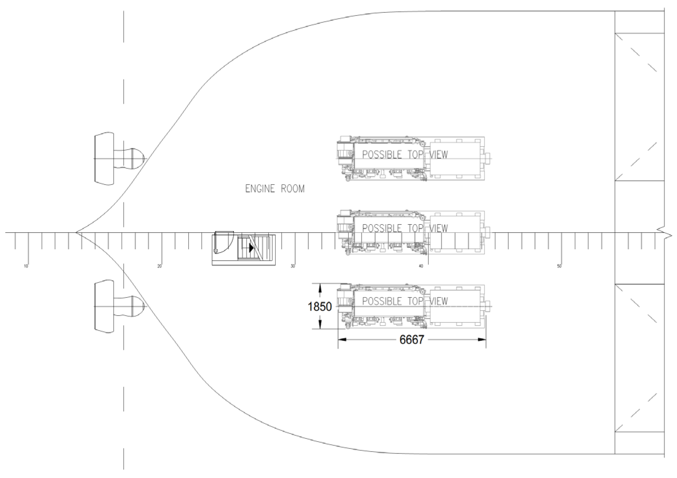
| 4. | Dimensions L × B × H [mm] | 6700 × 2010 × 2547 | 6700 × 2010 × 2831 | 6700 × 2010 × 2831 * | 6667 × 1850 × 3131 |
| 5. | Area required (engines + service area) [m2] acc. to design analysis | 61 | 61 | 61 | 59,4 |
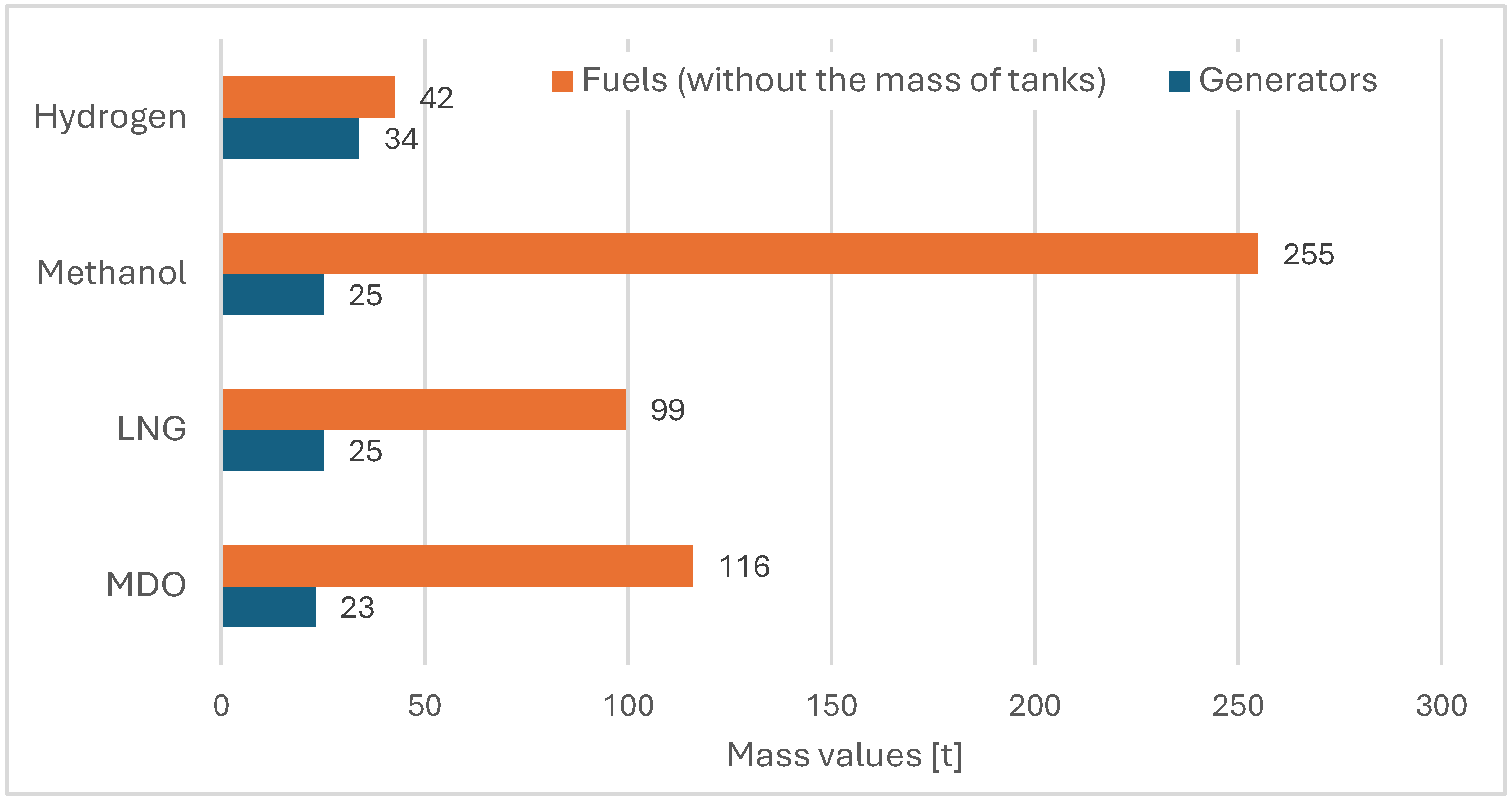
| 6. | Weight ME [t] | 23 | 25 | 25 *** | 33.7 |
| 7. | Fuel type | MDO, LFO, HFO | LNG, MDO, HFO | Methanol (M), MDO, LFO, HFO | Hydrogen (H2), MDO, LFO |
| 8. | IMO | Tier II or III | Tier II or III | Tier II or III | Tier III |
| No. | Property | Fuels | |||
|---|---|---|---|---|---|
| MDO | LNG (Liquid −163 °C) | Methanol (65 °C) | Hydrogen (Compressed 700 bar) | ||
| 1. | Density (kg/m3) | 830–850 | 410–500 | 787–792 | 40.2 |
| 2. | Emergency content LHV (MJ/kg) | 42.0–43.0 | 50.0 | 19.9–20 | 120.0 |
| 3. | Boiling point (°C) | 150–370 | −162.0 | 65.0 | −252.77 |
| 4. | Flash point (°C) | min. 60 | −188.0 | 9–11.0 | −259.20 |
| 5. | Auto ignition (°C) | 240.0 | 537.0 | 385.0–464.0 | 585.0 |
| 6. | Fuel tank size relative to MGO | 1.0 | 1.7 | 2.3 | 7.4 |
| No. | Parameter | Fuels | |||
|---|---|---|---|---|---|
| MDO | LNG | Methanol | Hydrogen | ||
| 1. | Total fuel reserve MTfuel [t] | 115.85 | 99.35 | 254.74 | 42.46 |
| The ratio of hydrogen to: | 0.37 | 0.43 | 0.17 | - | |
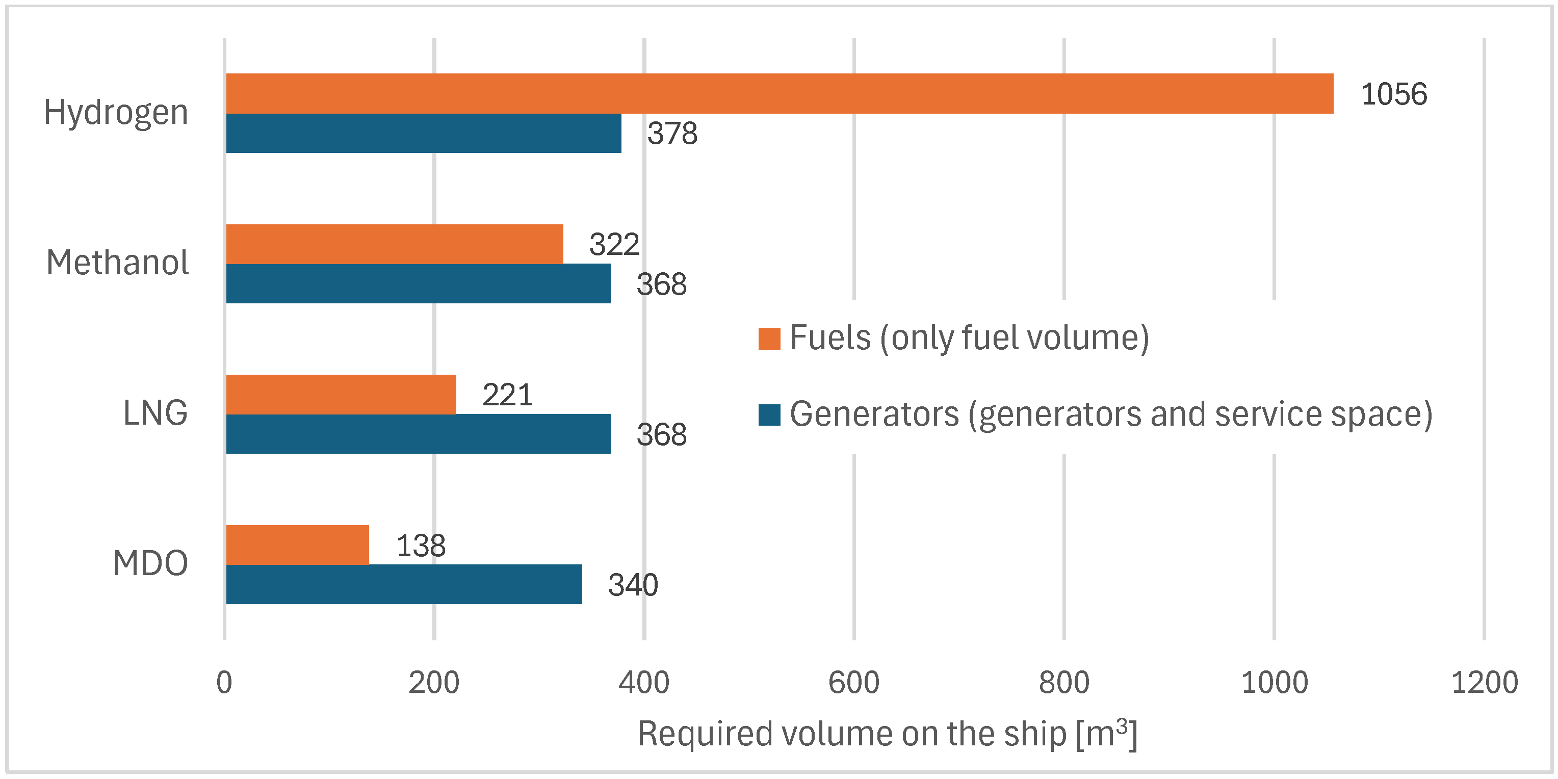
| 2. | Fuel volume Vfuel [m3] | 137.92 | 220.77 | 322.45 | 1056.13 |
| The ratio of hydrogen to: | 7.66 | 4.78 | 3.28 | - | |
| 3. | Fuel volume Vfuel [m3] | 137.92 | 218.57 LNG | 322.45 | 897.71 H2 |
| 1.38 MDO | 20.69 MDO | ||||
| 4. | Emergency content LHV [MJ/kg] | 43 | 50 | 20 | 120 |
| 5. | Fuel consumption per hour Gfuel [kg/h] | 266.94 | 228.91 | 586.96 | 97.83 |
| 6. | Specific fuel consumption gfuel [g/kWh] | 189.59 | 163.04 * | 407.61 * | 67.93 * |
| 7. | Area required (tanks + compartments required) [m2] acc. to design analysis | 230 | 264 | 360 | 1539 impossible |
| No. | Endurance | Hydrogen Mass [t] | Hydrogen Volume [m2] | Hydrogen Volume Minus MDO [m3] | Number of Cylinders [pcs]. |
|---|---|---|---|---|---|
| 1. | 1 day | 3.03 | 75.44 | 65.68 | 150 |
| 2. | 3 days | 9.10 | 226.31 | 205.75 | 449 |
| 3. | 5 days | 15.16 | 377.19 | 342.91 | 749 |
| 4. | 7 days | 21.23 | 528.07 | 480.08 | 1048 |
| 5. | 9 days | 27.29 | 678.94 | 617.24 | 1348 |
| 6. | 11 days | 33.36 | 829.82 | 754.40 | 1647 |
| 7. | 13 days | 39.42 | 980.69 | 891.57 | 1947 |
| 8. | 14 days | 42.46 | 1056.13 | 960.15 | 2096 |
| No. | Parameter | Operational Profile and Phases of SOV Service Work | |||||
|---|---|---|---|---|---|---|---|
| I | II | III | IV | V | Normal Operation | ||
| 1. | Power requirement PR′ [kW] | 2851 | 1526 | 1976 | 773 | 1426 | 2190 |
| 2. | Time operating T [hours/day] | 3.5 | 1.5 | 3.5 | 1.0 | 14.5 | 8 total |
| Configuration of 3 generating sets with the same power | |||||||
| 3. | Number of working Generators | 2 | 1 | 2 | 1 | 1 | 2 |
| 4. | Rated power PR [kW] | 1800 1800 | 1800 | 1800 1800 | 1800 | 1800 | 1800 1800 |
| 5. | Engine load Eload (%) | 79 | 85 | 55 | 43 | 79 | 61 |
| Configuration of 3 generating sets with different power | |||||||
| 6. | Number of working generators | 2 | 1 | 1 | 1 | 1 | 2 |
| 7. | Rated power PR [kW] | 2400 1200 | 1800 | 2400 | 1200 | 1800 | 1800 1200 |
| 8. | Engine load Eload (%) | 79 | 85 | 82 | 64 | 79 | 73 |
| No. | Endurance | Number of Cylinder Modules [pcs] | Area for Cylinder Modules in the Hull [m2] | Volume of Cylinder Modules in the Hull [m3] | Percentage Share of Underwater Hull Volume |
|---|---|---|---|---|---|
| 1. | 1 day | 17 | 110 | 228 | 5.0 |
| 2. | 3 days | 50 | 330 | 685 | 9.0 |
| 3. | 5 days | 83 | 550 | 1142 | 23.0 |
| 4. | 7 days | 116 | 769 | 1599 | 33.0 |
| 5. | 9 days | 150 | 989 | 2056 | 42.0 |
| 6. | 11 days | 183 | 1209 | 2513 | 51.0 |
| 7. | 13 days | 216 | 1429 | 2970 | 61.0 |
| 8. | 14 days | 233 | 1539 | 3198 | 66.0 |
Disclaimer/Publisher’s Note: The statements, opinions and data contained in all publications are solely those of the individual author(s) and contributor(s) and not of MDPI and/or the editor(s). MDPI and/or the editor(s) disclaim responsibility for any injury to people or property resulting from any ideas, methods, instructions or products referred to in the content. |
© 2024 by the authors. Licensee MDPI, Basel, Switzerland. This article is an open access article distributed under the terms and conditions of the Creative Commons Attribution (CC BY) license (https://creativecommons.org/licenses/by/4.0/).
Share and Cite
Bortnowska, M.; Zmuda, A. The Possibility of Using Hydrogen as a Green Alternative to Traditional Marine Fuels on an Offshore Vessel Serving Wind Farms. Energies 2024, 17, 5915. https://doi.org/10.3390/en17235915
Bortnowska M, Zmuda A. The Possibility of Using Hydrogen as a Green Alternative to Traditional Marine Fuels on an Offshore Vessel Serving Wind Farms. Energies. 2024; 17(23):5915. https://doi.org/10.3390/en17235915
Chicago/Turabian StyleBortnowska, Monika, and Arkadiusz Zmuda. 2024. "The Possibility of Using Hydrogen as a Green Alternative to Traditional Marine Fuels on an Offshore Vessel Serving Wind Farms" Energies 17, no. 23: 5915. https://doi.org/10.3390/en17235915
APA StyleBortnowska, M., & Zmuda, A. (2024). The Possibility of Using Hydrogen as a Green Alternative to Traditional Marine Fuels on an Offshore Vessel Serving Wind Farms. Energies, 17(23), 5915. https://doi.org/10.3390/en17235915