Abstract
Energy transition and decarbonization present significant challenges to transportation. Electric machines, such as motors and generators, are increasingly replacing internal combustion engines to reduce greenhouse gas emissions. This study focuses on enhancing the energy efficiency of electric machines used in vehicles, which are predominantly powered by batteries with limited energy capacity. By investigating various control strategies, the aim is to minimize energy losses and improve overall vehicle performance. This research examines two types of electric motors: Permanent Magnet Synchronous Motor (PMSM) and Induction Motor (IM). Real-time loss measurements were conducted during simulated driving cycles, including acceleration, constant speed, and braking phases, to mimic typical driving behavior. The simulation utilized characteristics from commercial vehicles, specifically the Renault Zoé and Bombardier eCommander, to assess the controls under different configurations. This study employed the Energetic Macroscopic Representation (EMR) formalism to standardize the analysis across different motors and controls. The results demonstrate significant loss reductions. The controls investigated in this study effectively reduce energy losses in electric motors, supporting their applicability in the automotive industry.
1. Introduction
Energy transition and carbonation are significant challenges to the future of transportation. The use of electric machines—motors and generators—is increasing in order to replace more polluting internal combustion engines, which emit greenhouse gases.
When these machines are used in the transportation sector, they are mostly powered by a battery with limited energy capacity. The technologies used in these batteries vary, including Nickel-Cadmium (Ni-Cd), Lithium-Ion (Li-Ion), or, more recently, Sodium-Ion (Na-Ion) batteries. Their purpose is to convert chemical energy into electrical energy. Two important parameters to consider are the maximum power the battery can provide and its capacity. These elements are crucial for the vehicle as they define its performance.
However, the role of the battery is almost exclusively reserved for powering the motor, with onboard equipment consuming very little current. Consequently, it is deduced that the motor must consume as little energy as possible to increase the power supply of the battery duration and, consequently, the distance traveled. Similarly, energy savings translate into financial savings on recharging. It should be noted that the project will focus solely on the “tank to wheel” aspect.
In this context, this study aims to report on energy-efficient controls for electric machines in order to reduce losses across all operating conditions. The topic is deliberately open to exploring a wide range of different controls and covering a significant portion of what can be conducted in electric propulsion.
Their various applications range from electric scooters to electric cars, as well as electric ships (not addressed in this article). Reducing the losses of each of these means of transportation helps decrease the energy consumption from an ecological perspective.
As mentioned previously, the objective of this work is to reduce the energy losses of electric motor vehicles. Recent articles in this ecological perspective focus only on a single control and a single motor, whereas here, the aim is to compare these works. Two motors will be the objects of this study. These motors were chosen because they are essential and still widely used today: the Permanent Magnet Synchronous Motor (PMSM) and the Asynchronous Motor, also called the Induction Motor.
The losses of the different motors will be measured in real time during cycles consisting of acceleration phases, constant speed phases, and braking phases. These cycles mimic the behavior of an ordinary driver and will allow obtaining the losses that a motor could experience on a daily commute. The latest cycle used is the “Worldwide harmonized Light vehicles Test Procedure” (WLTP) cycle, which will be utilized in the article.
To simulate the behavior of a car as accurately as possible, the motor must be simulated within the architecture of a commercialized vehicle. For this reason, the characteristics of the two vehicles have been implemented in the simulator. These two cars are the “Renault Zoé” and the “Bombardier eCommander”, which will allow testing whether the controls work in two completely different configurations (weight, road quality, etc.).
Finally, throughout the article, the same representation formalism is used. Regardless of the motor and its configuration, the power train will be represented in the same way. The adopted formalism is the Energetic Macroscopic Representation (EMR) [1], which can be used to represent cars, bicycles, or other energy systems. For the different control chains, the Maximum Control Structure (MCS) [2] will be preferred as it works in conjunction with the EMR. Using these two tools will simplify the understanding and operation of the simulated controls.
The first section (Section 2) presents the Energetic Macroscopic Representation used to organize all the different control schemes. The second section (Section 3) exposes the Energetic Macroscopic Representation of an electric vehicle and the Worldwide harmonized Light vehicles Test Procedure (WLTP) cycle. The next two sections present comparative studies of various control schemes for the permanent magnet synchronous motors (Section 4) and for the asynchronous motor (Section 5). Finally, Section 6 draws conclusions.
2. Methods and Generic Control Scheme
In order to organize the model and the control of the car, the Energetic Macroscopic Representation (EMR) [1] is used. This is a graphical method that enables the breaking down of the system model into control-oriented components, facilitating the systematic derivation of control schemes. The EMR serves as a roadmap for simplifying the model to create a straightforward vehicle simulation. EMR is used for modeling electrical vehicles [3,4], subway [5], fuel cell [6], wind energy conversion systems [7]. In this paper, several motors and control laws will be evaluated. Then, a generic scheme of the dynamical model and the control process is presented in Figure 1. The orange or yellow blocks represent the plant, i.e., the motor, the batteries, and the environment of the car. The blue blocks stand for the controller (one-speed controller and the specific control block for different motors). All the need blocks in the EMR formalism are presented in detail in the next sections. The parameters and variables of the vehicle are described in Table 1.
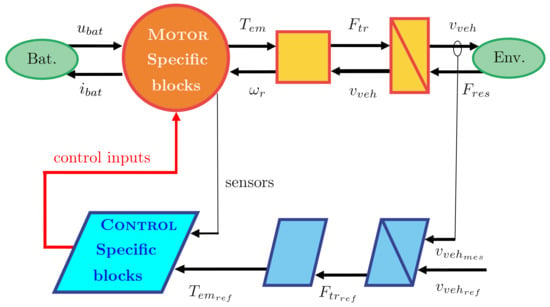
Figure 1.
Energetic macroscopic representation (EMR) of the electrical vehicle.

Table 1.
Vehicle parameters and variables.
Numerical simulations are carried out using the Matlab/Simulink r2011b software.
3. Dynamical Model of the Vehicle
This section provides the details of the modeling used for the electric vehicle.
- Batteries are modeled as follows:Simulations use battery cells with capacity of 72 Ah and serial resistance of m, 4 cells in parallel, 48 cells in series.
- Gearbox:In the simulation, the gearbox ratio is adjusted for each engine so that the vehicle can complete the test without the engine exceeding its nominal value (no defluxing).
- Wheels:
- Vehicle body:
- External environment:
The three control blocks correspond to a speed controller to give reference force needed on the wheel, an inversion of the wheels and gearbox block, and finally, a specific block for the electric motor low-level controller. The speed controller is given by
where is a PI controller. Controller gains are chosen by fixing a second-order dynamic of the vehicle’s close loop with and . Numerical values are and with s.
Inversion of the wheels relation gives
Inversion of gearbox relation reads
3.1. Speed Cycles
In order to test the vehicle performances in a simulation environment, it is necessary to reproduce driving conditions similar to those of the real world.
The driving cycle WLTP or “Worldwide harmonized Light vehicles Test Procedure” is the new European standard for vehicle testing [8,9]. This cycle is depicted in Figure 2. Since 2018, all new vehicles leaving the factory run through this simulator in order to measure the fuel consumption, exhaust emissions of combustion models, and measure the range of electric vehicles. The cycle has a duration of 1800 s or 30 min and comprises four phases. The first two phases represent an urban cycle, while the last two are extra-urban, with a maximum speed of 131 km/h. The accelerations and decelerations are designed to best represent human behavior.
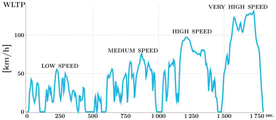
Figure 2.
Worldwide harmonized Light vehicles Test Procedure (WLTP) cycle.
The resisting force applied to the motor in Figure 1 is given by the external environment formula. Within this formula, three parts can be distinguished.
To begin with, the first part models the rolling force with f as the rolling resistance coefficient, as the vehicle mass, g as the acceleration of gravity ( m/s2), and as the angle of slope here: 0 deg.
Next, the aerodynamic force is the force exerted by air on the moving vehicle. The parameters are as the density of the air (1.204 kg/m3); the variables and , respectively, denote the speed of the vehicle and the wind (in the simulation, the wind will be considered zero); and the aerodynamic drag coefficient, which depends on the exposed frontal surface and the shape of the front of the vehicle. The better the air penetration of the vehicle, the smaller the coefficient. Finally, the last part of the equation models the force due to the road slope. The sum of the various resisting forces is added to the mass multiplied by the acceleration in the chassis block.
3.2. Simulated Vehicles
Two different sets of parameters (see Table 2) are used to faithfully simulate the vehicles in the Figure 3, and are detailed in the following table. The weight of the vehicle indicated does not include the two passengers of 75 kg on board.

Table 2.
Simulated vehicle parameters.
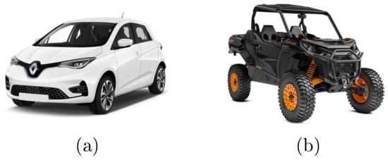
Figure 3.
Simulated vehicles: (a) Renault Zoé and (b) Bombardier eCommander.
The “Renault Zoé” (Figure 3a) is a 100% electric car created for the general public. It is undoubtedly the flagship of the Renault group in the green car sector. Since 2013, the Zoé has been one of the best-selling electric vehicles on the market. This is a city car designed to cover daily commutes, with a range of around 300 km. Its size and weight are therefore relatively small compared with other cars on the market.
The “Bombardier eCommander” (Figure 3b) is an all-terrain vehicle. It can be used for utility or leisure purposes. Its 29″ wheels give it solid road holding and the ability to negotiate all kinds of obstacles. Its primary frame, lightweight materials, and limited equipment all help to reduce the weight of the vehicle and hence fuel consumption.
The WLTP cycle will be the control comparison tool, the aim being to measure motor losses over a complete or partial cycle and compare these losses with another control for the two presented vehicles.
4. Comparative Study of Different Control Scheme for Permanent Magnet Synchronous Motor
4.1. Modeling of the PMSM
4.1.1. Motor Model
The electrical part of the pmsm is generally modeled as in Figure 4. In order to simplify the three-phase equations, it is necessary to use the classical Park transformation.
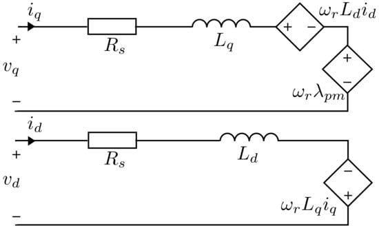
Figure 4.
PMSM ideal circuits.
The parameters and variables of the PMSM are described in Table 3.

Table 3.
PMSM parameters and variables.
The equations of the Permanent Magnet Synchronous Motor are deduced from Figure 4
Equation (10) is expressed in terms of the counter-electromotive forces
Using the right-hand rule, the torque is represented by a vector in the axial direction. It is obtained by calculating the vector product between the fluxes and currents of the axes. The torque developed by the motor is given by
Because and in the rotating synchronous frame.
Two parts can be distinguished within the electromagnetic torque : the main torque and the reluctant torque which only appears if .
4.1.2. Difference between SPMSM and IPMSM
The inductances and depend on the motor design. The choice of permanent magnet positioning will influence torque generation. There are two main configurations for the pmsm.
The Surface-Mounted Permanent Magnet Synchronous Motor (SPMSM) (Figure 5a) torque generation is unique in that its permanent magnets are positioned on the outer surface of the rotor. This makes its design fairly straightforward [10]. However, as its magnets are directly exposed to the magnetic field, the stator inductances and are similar. It cannot produce reluctant torque.
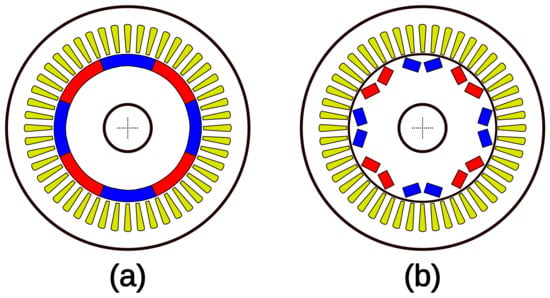
Figure 5.
SPMSM (a) vs. IPMSM (b).
The Interior Permanent Magnet Synchronous Motor (IPMSM) (Figure 5b) unlike the SPMSM can produce reluctant torque. In a large number of applications, such as position or precision control, reluctance (opposition of the magnetic circuit to a magnetic field) is a parasitic quantity that we seek to suppress. However, in our case (speed control), reluctance can be controlled to obtain a magnetic opposition to our advantage (creating additional torque).
Reluctance appears in the IPMSM because its magnets are integrated into the rotor and can be arranged in a different way [11]. For example, Toyota uses a V-shaped arrangement in its hybrid vehicles. The skewed exposure of the permanent magnets will create a difference between the inductances and . This difference is used to create a reluctant torque. The IPMSM will be characterized by its salience ratio (/). The higher this ratio, the greater the torque density. Several techniques exist to increase this ratio: for example, multiplying magnet layers (Figure 6b) or axial laminations (Figure 6c).
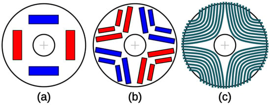
Figure 6.
Increasing saliency ratio. (b) multiplying magnet layers with respect to (a). (c) represents axial laminations effect.
Synchronous motor control research will focus exclusively on ipmsm, as loss-reducing controls have more potential.
4.1.3. Losses Models
The copper losses in Equation (14) are due to the Joule effect caused by the heating of the winding wires. The coefficient comes from the formula in three phases with the stator resistance in view of the star configuration.
By slightly modifying Figure 4, a model closer to reality can be obtained [12]. Figure 7 adds a resistor representing iron losses within the motor. The currents and will now be divided into two parts: the currents producing the torque; and the currents producing the iron losses.
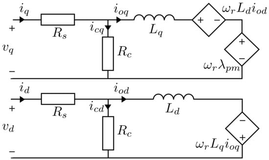
Figure 7.
PMSM circuits.
The iron losses are made up of hysteresis and Eddy-current losses. These are losses occurring within the ferromagnetic core, and from [12] iron losses are given by
Using the diagram in Figure 7, the values of the currents and are deduced in steady state (with respect to the electrical time constant) as follows:
As well as currents and with Kirchhoff’s current law
The electromagnetic torque will only be produced by and
4.2. EMR of the Permanent Magnet Synchronous Motor
Blocks specific to the IPMSM have been added to the common blocks of Figure 1. These blocks are defined by the following model equations:
- The smoothing coil (to protect the battery from current peaks)
- DC bus capacity
- The inverter or DC/AC converter
- Park transformation
- d,q armatures
- Electromagnetic conversion
Additional parameters and variables are defined in Table 4. Three-phase variables will have the notation .

Table 4.
Supplementary PMSM parameters and variables.
This gives the EMR of the pull chain from IPMSM to Figure 8. The added blocks are orange.

Figure 8.
IPMSM vehicle EMR scheme.
4.3. Parameters of Selected Permanent Magnet Synchronous Motors
Below, Table 5 contains motor parameters found in various articles [13,14,15,16,17,18,19,20,21]. These motors have power ratings ranging from 40 to 120 kW, corresponding to the power range of an all-terrain quad or an electric city car. Note that the Renault Zoé R135ch ≈ 100 kW. We chose to set the value of to 8 in order to observe iron losses of the order of 10% of total losses. The goal of our study is not to vary each parameter set individually, but to choose a parameter set large enough to obtain a thorough study.

Table 5.
IPMSM motor parameters.
4.4. Control Scheme Comparison
4.4.1. Zdac Control Law
The Zero d-axis current or ZDAC control is the simplest control applied to PMSM [22]. It allows you to leave the current at zero, so you only need to manage to produce torque. The current comes simply from Equation (19) with , as follows:
This control law only takes advantage of the production of the main torque. This control seeks to imitate the behavior of an MCC. The following specific blocks have been added (Figure 9). These include the use of a PI corrector and the inverse Park transform. The gains of the PI corrector are computed to impose response time () of the closed loop: and with ms. This gives the Maximum Control Structure (MCS) for ZDAC in Figure 10.
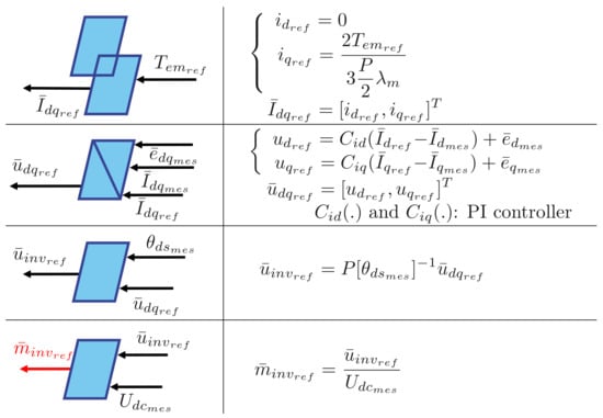
Figure 9.
ZDAC control scheme specific blocks.
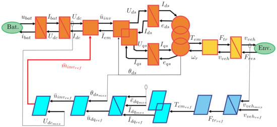
Figure 10.
Control structure for ZDAC.
4.4.2. Mtpa Control Scheme
As its name suggests, the Maximum Torque Per Ampere (MTPA) control law attempts to produce the maximum torque produced. By using the reluctant torque of the IPMSM, it will enable the vehicle to achieve good performance by distributing its current more evenly. The current reference will no longer be fixed at zero but will contribute to torque generation in the same way as . As copper losses are quadratic, the current distribution between and will increase motor efficiency. Knowing that, . As the total stator current , the losses can be different depending on the distribution between and [23]. Note that and , then the copper losses become . In the interval , the minimum is achieved for and the maxima are located at and . Loss maxima are therefore when or . At first sight, is the solution with the lowest losses, but and do not produce the same amount of torque. Depending on the motor and profile, the coefficient will vary in order to meet the torque of the motor requirements and minimize motor losses. This issue is illustrated in Figure 11, with , which can be distributed in different ways. The red dot point (, ) generates fewer losses than the blue dot point (, ) but produces much less torque. The MTPA control attempts to resolve this compromise.
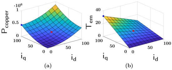
Figure 11.
Copper losses (a) and torque generation (b) with respect to current distribution.
The MTPA technique focuses only on suppressing copper losses; iron losses are ignored for the control design (), so and because A [24].
We need to solve Equation (21) to find the maximum voltage per ampere
The optimal current is obtained as follows:
The current is determined by the following relationship:
where is the stator current required by the motor to deliver the required torque. First, check that , if not, then saturate it at . The sign of the current will be the same as that of . If , the car is in traction mode. If , the car is in regenerative braking mode. Note that and designate the same thing: the reference input of the block. The two variables are proportional.
The added control blocks are those shown in Figure 9 except for the strategy block, which includes Equations (22) and (23). This gives the maximum MTPA control structure, shown in Figure 12:
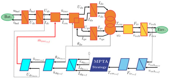
Figure 12.
MTPA controller scheme.
4.4.3. Lm/Mtpa Controller
The Losses Minimization/Maximum Torque Per Ampere controller (LM/MTPA) is a hybrid controller combining the MTPA control and the LM control. The choice of which control will prevail over the other is made by adjusting parameter [12].
The MTPA control previously presented is known to perform well during speed changes and to drastically reduce copper losses, but it does not take into account the iron losses of the motor. The LM control is known to perform less well dynamically but reduces both copper and iron losses. For optimum control, the MTPA control should be used during speed changes and the LM control the rest of the time. This means ignoring iron losses during high torque demand but continuing to take them into account the rest of the time. The parameter is used to weight the iron losses taken into account. The losses taken into account for the control design are described by Equation (24).
If , then iron losses are taken into account. The aim is to minimize all motor losses (LM control). If , only copper losses are taken into account. The aim is to maximize torque per ampere (MTPA control).
To calculate , we chose the absolute value of the derivative of torque . This is multiplied by a gain of 10 on the nominal torque. The slope of the must also be saturated and limited. The aim is for the greatest possible torque demand to bring down to zero. This method replaces the [12] method, which is based on the difference between the reference speed and the measured speed.
To find the optimum trajectory, the mathematical solution is as follows: the losses in Equation (24) are derived with respect to current (torque-producing current on axis d) and the roots are found (Equation (25)).
Once developed, the aim is to make the pair appear in the Equation (25). This gives an equation to solve of the type (26)):
The previous equation can be written as follows:
With the following coefficients A, B, and C:
We need to reformulate Equation (27) and find its smallest root, which is the optimal current value . This optimum current will depend on the three inputs , , and . Next, use Equation (19) to find and Equation (17) to obtain and .
The control blocks added are those shown in Figure 9, except for the strategy block LM/MTPA, which uses Equation (27), and the “strategy ” block, which uses the scheme (Figure 13). This gives the Maximum Control Structure (MCS) for LM/MTPA, shown in Figure 14.

Figure 13.
Calculation of .
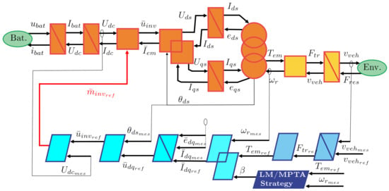
Figure 14.
LM/MTPA controller scheme.
4.4.4. Comparative Results
Cycles and durations were chosen to run the engine at a speed below the nominal speed of the motor (no defluxing). The architecture of the Zoe will be simulated for all engines, except for the IPMSM1, which will be with a Bombardier architecture as it is less powerful than the others. Table 6 presents simulation results of the different motors with parameters from Table 5. Note that some engine numbers are missing, as the corresponding engines were not selected because they were not powerful enough or parameters were missing.

Table 6.
Results table for ZDAC, MTPA, and LM/MTPA controllers.
Table 7 contains data from additional simulated engines to confirm that trend curves are emerging. Figure 15 is used to observe the gain for MTPA and LM/MTPA control with respect to ZDAC control. These gains vary greatly from one motor to another. We will see later that these gains depend on certain motor parameters.

Table 7.
Parameters for IPMSM motor.
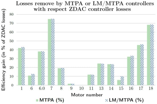
Figure 15.
Comparison of regained losses with respect to ZDAC control.
The Figure 16 and Figure 17 show that in this power range and operating zone, the benefits of the commands MTPA and LM/MTPA can be predicted by the ratio of reluctant torque to the main torque: . Below the ratio mH/Wb a straight line emerges, with the trend becoming logarithmic beyond that. The regression line has been plotted on Figure 16. The red dots on the curve represent the verification engines (15 to 18).
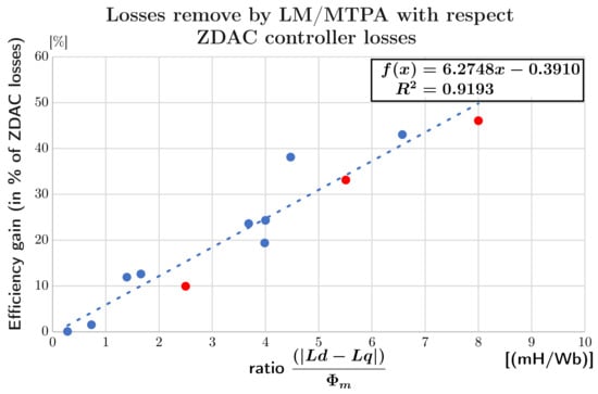
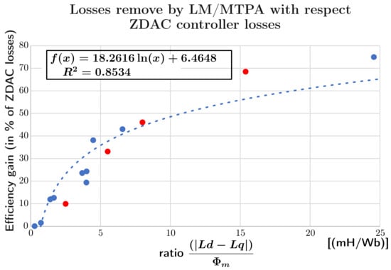
Figure 17.
Losses deleted based on the ratio —extended area.
Taking motor number 6 as an example, the current distribution (red) and (blue) is shown in Figure 18. On the left (Figure 18a), the distribution for the control ZDAC with current zero. On the right (Figure 18b), the distribution for the LM/MTPA control with the two currents and which reduce the amplitude of the currents (475 A versus 390 A).
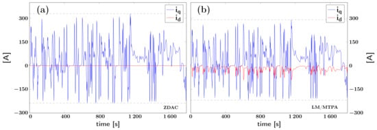
Figure 18.
Current distribution comparison: (a) ZDAC—(b) LM/MTPA.
Table 8 shows the yields of the best and worst control on each motor. Gross efficiencies depend largely on the value of the stator resistance and the amplitude of the circulating currents (Equation (34)). The higher the value, the lower the motor efficiency. But, the higher , the more effective the MTPA strategy will be (greater efficiency difference). In the same way as the ratio , the value of can be interesting to analyze in order to anticipate losses that can be eliminated before implementing the control on a motor.

Table 8.
Comparison of energy efficiency.
In conclusion, the MTPA and LM/MTPA controls make it possible to eliminate a significant proportion of losses by using reluctant torque in addition to the main torque. Their simplicity of installation makes them easy to integrate into motors coming out of the industry or already on the road. In addition, as motors age, stator resistance tends to increase slightly, so the losses eliminated by these two controls will become more expensive. The choice between MTPA and LM/MTPA is in the hands of the expert. Indeed, in the above case, the difference is not obvious, but if the voltage and frequency of the supply increase, a discrepancy will be created. Finally, detecting a link between suppressed losses and the ratio of main torque to reluctant torque enables us to predict the gains to be made by implementing these controls. A reading of the motor parameters can indicate the relevance or otherwise of changing standard control by these improved controls.
5. Comparative Study of Different Control Scheme for Asynchronous Motor
5.1. Modeling
5.1.1. Asynchronous Motor Model
The basic principle of the asynchronous motor may be similar to that of the PMSM, but there are some major differences. The rotor of the asynchronous machine has no permanent magnets, but a cage with iron bars (squirrel cage). The stator field created will sweep across the rotor bars, causing currents to flow in the same direction. This is due to the phenomenon of induction: the stator will induce currents in the rotor bars that would otherwise not need to be energized. The rotor will not reach synchronous speed, and there will always be an offset, known as slip. Asynchronous motor variables and parameters are given in Table 9. The equivalent phase diagrams of the asynchronous motor are shown in Figure 19.

Table 9.
Asynchronous motor variables and parameters.
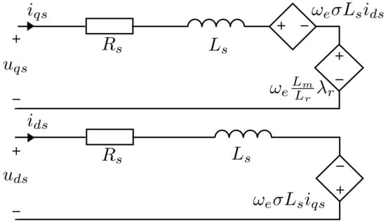
Figure 19.
Asynchronous motor wiring diagrams.
The equations of the asynchronous motor are described below. As with the PMSM, we need to go through the Park transformation. Equations (28)–(32) are taken from [25]. The stator voltages of the d and q armatures
Pseudo counter-electromotive forces, as follows:
With and . The torque formula follows the same principle as Equation (13), as follows:
The rotor magnetization below clearly shows that the flux inside the motor is dependent on , as follows:
Now, we choose the orientation of the reference frame so as to have and . The torque formula thus becomes
And this gives in steady state
5.1.2. Losses Model
The loss model below is taken from the articles [26,27,28]. Copper losses represent Joule effect losses in the stator and rotor, as follows:
Here, the current is zero because according to the rotor voltage formula and .
Iron losses are composed of hysteresis and Eddy current losses
where .
5.2. EMR of Asynchronous Motors
The blocks specific to the Asynchronous Motor drive train are given by the following expression:
- Rotor magnetization
- Electromagnetic conversion
The EMR of the asynchronous motor vehicle is given on Figure 20 (by reusing common blocks of Figure 1 and Figure 8).

Figure 20.
Energetic macroscopic representation of a vehicle with asynchronous motor.
5.3. Parameters of Selected Asynchronous Motors
Table 10 containing the motor parameters taken from the article [29]. These motors range in power from 37.5 to 160 kW, corresponding to the power range of an electric city car (Renault Zoé R135ch ≈ 100 kW).

Table 10.
Asynchronous Motor parameters.
5.4. Controller Comparison
5.4.1. Field-Oriented Control (FOC)
The aim of field-oriented control is to decouple flux and torque. The first step is to set the nominal flux at a constant value. The relationship (31) ensures that the reference current remains at a constant value. Nominal flux is usually calculated using the formula . This formula was not used, as the current is calculated from tests on the motor at no load. Another formula simulating this behavior was preferred, as follows:
The reference flux () used in our simulation comes from Formula (37).
On the other axis, the current ensures that torque demand is met by returning the torque in Equation (30).The aim is for the torque of the asynchronous motor to depend on a single current, as in a DC motor. This equation is detailed and linked to the blocks on Figure 21.
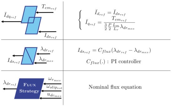
Figure 21.
Specific MAS FOC blocks.
Figure 22 shows the complete representation of the FOC scheme.
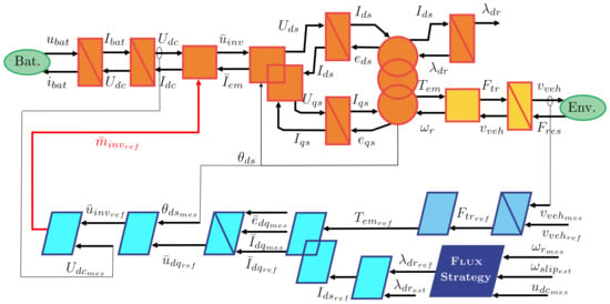
Figure 22.
EMR asynchronous motor FOC.
5.4.2. Optimized Flux Control 1
The aim of the Optimized Flux Control 1, 2, and 3 is to modulate the flux () instead of leaving it constant. Indeed, the FOC method keeps a constant medium-high flux regardless of torque demand, in order to simplify its implementation. This constant flux results in the permanent circulation of a current, which in turn generates copper and iron losses.
The main problem with the FOC control is, why leave at a high value when there is no torque demand? The way to reduce losses is to leave at zero or close to zero when there is no torque demand and to find the best combination between and when torque demand occurs. Indexing the current to torque demand would not only meet dynamic requirements quickly, but also reduce current-related losses when the profile is smooth.
The first method (Opt_flux_1) comes from the article [26] published in 2021, this method seeks the optimal flux to cause the minimum losses. Since the optimal flux and current are very closely related, finding the optimal flux and current amounts to the same thing. The article begins its reasoning by looking for the steady-state torque (Equation (33)) in Equation (34), the loss model becomes
- Copper losses:with .
- Iron losses:
Total losses:
In order to obtain the flux with the lowest losses, we need to derive the total losses with respect to and find the smallest root: . Inserting (38) and (39) into the previous equation gives
The expression is simplified within an equivalent resistor . By isolating on one side, we obtain the equation
The optimal flux is therefore
The maximum structure for optimal flux control is added to the EMR in Figure 23. The added blocks are similar to the FOC except for the strategy block, which contains Equation (43).
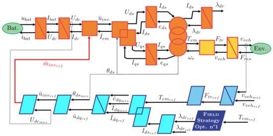
Figure 23.
EMR control structure for Optimized Flux Control 1.
5.4.3. Optimized Flux Control 2
The second method (Opt_flux_2) comes from the article [27], published in 2022. The principle is similar, but the model is slightly different and the method changes, as optimal currents are calculated immediately. Here, the flux is not used directly. Based on the loss model in the article, the following equation appears:
With the magnetizing voltages of the d and q branches representing the coupling between the voltages and currents of the d and q axes,
Unlike the Optimized Flux Control 1, we derive the total losses with respect to the current to obtain the minimum losses.
Or
The blocks of the control chain are similar to the previous ones except for the strategy block, which includes the following equations:
Assembling the traction chain and control blocks gives the complete EMR diagram (Figure 24).
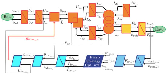
Figure 24.
EMR control structure for Optimized Flux Control 2.
5.4.4. Optimized Flux Control 3
The last method (Opt_flux_3) comes from the article [28], published in 2023. In the same way, the starting point is the loss model of the motor, and the aim is to minimize total losses by deriving them with respect to current . The current is given by the following equation:
With the following coefficients A, B, and C:
The difference here is that iron losses have not been simplified within an iron resistor . This gives the complete EMR diagram (Figure 25).
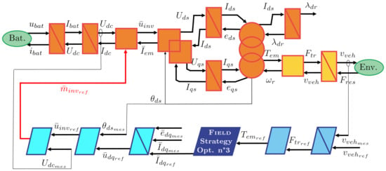
Figure 25.
EMR control structure for Optimized Flux Control 3.
5.4.5. Results
The Table 11 below gathers the loss results of the four previous control scheme after a complete cycle. The aim is to reach the same operating region as for IPMSM. With the exception of the MAS4 and MAS17 (less powerful), which are simulated with Bombardier architecture, all other vehicles are simulated with Zoé architecture.

Table 11.
Table of results for , Opt_flux_1, Opt_flux_2, and Opt_flux_3 control scheme.
Figure 26 shows the evolution of flux as a function of time. The three strategies applied are similar, but with a few differences that appear according to motor speed.
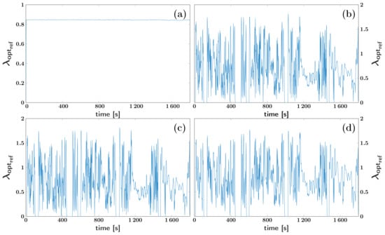
Figure 26.
Flux comparison: (a) FOC—(b) —(c) —(d) .
Figure 27 is used to compare gains with losses in relation to the FOC control. The control performs better on motors with lower power ratings (MAS4, MAS12, and MAS17). Whereas the control stands out on more powerful motors (MAS6, MAS7, MAS18, MAS19, and MAS20). As for the control, it is more constant regardless of motor power. We can conclude that, whatever the control chosen, the losses suppressed are quite significant compared with the FOC control, but depending on motor power, one of the three flux-optimized controls will perform better.
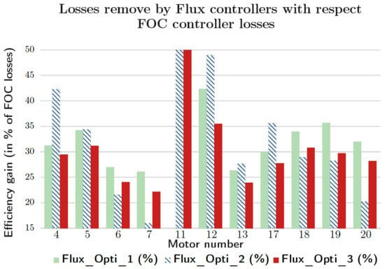
Figure 27.
Comparison of regained losses.
Table 12 shows the yields of the best and worst controllers on each of the MAS. The raw efficiencies depend on the values of the components (rotor and stator resistances and inductances). By choosing the most suitable control for the asynchronous motor, the efficiency of each motor can be increased by 1.1% to 2.8%. The performance of the controls applied depends little on the motor configuration, and gains can be observed on all ten motors presented.

Table 12.
Comparison of motor efficiencies.
6. Conclusions
In conclusion, the various controls applied to the two motors have performed well as they have allowed for a significant reduction in losses. The EMR/MSC representation has been successful in facilitating the understanding of the different controls. This paper shows that the Energy Macroscopic Representation (EMR) formalism, introduced a decade ago, is very practical for making the comparisons we have made in this paper. EMR offers a unified structure for the graphical presentation of system models and control laws. To switch from one control law to another, it is sufficient to change an instance of one or more blocks. The overall structure of the diagram remains the same.
The results obtained, simulated under conditions resembling those of a typical driving cycle, suggest that the controls are applicable in the automotive industry.
The more complex motors presented in the article justified the implementation of controls aimed at reducing energy consumption. In these motors, two currents and flow. Historically, the most well-known controls chose to use only one of these currents () to produce torque. The current was thus constant or zero, either used for flux regulation or not used at all. The advantage was that the control of these motors was close to a Direct Torque Control (DTC). However, the loss in torque production and the losses incurred by the flow of a constant current were significant drawbacks.
The aim of this work is to demonstrate that controls taking into account these losses exist for all motors and allow for energy savings while maintaining good performance. The methodology was to present the known motor model along with its loss model and then represent them with the EMR. Subsequently, different controls seeking to minimize total losses were simulated.
For the PMSM, the LM/MTPA control was the most effective in considering copper and iron losses. Its implementation over ten motors demonstrated its effectiveness with an average of 25% of losses eliminated and an average efficiency increase of 3.2%. However, it should be noted that the benefits of this control depend heavily on the motor parameters on which the control is implemented. Hence, the eliminated losses were expressed as a ratio between the main torque and the reluctance torque to predict the performance of any IPMSM control.
In summary, the experiment highlighted controls reducing losses in two different motors. A uniform representation was used throughout the work with EMR and MSC to simplify the understanding of energy exchanges. The results we have reviewed in this study are interesting in practice. They have immediate applications. Indeed, the control laws of electric motors are already implemented on computers today. To implement more efficient laws, it is enough to change the software without changing the hardware. There is therefore no significant economic impact of updating the control laws on an existing fleet of electric machines. Future prospects for the project would involve conducting similar work on the Synchronous Reluctance Motor (SRM), integrating motor loss representation into the EMR, and continuing work above the nominal speed of the motor (constant power region).
We believe that a similar study on Brushless DC (BLDC) motors is worth conducting. These motors are becoming important in many aspects of the industry because they are less expensive than synchronous motors or induction motors.
More precisely, this work does not only apply to electric motor controls but also to all areas that use variable-speed motors. For a more global study of the electric vehicle, a broader study could be conducted to include losses related to batteries or supercapacitors.
Finally, it should be noted that similar gains could be gained in any industrial use of electric drive (marine propulsion, dump truck, machine tools, energy conversion, etc.).
Author Contributions
Conceptualization, J.-M.B., R.L. and E.D.; methodology, J.-M.B., R.L. and E.D.; software, R.L.; validation, J.-M.B., R.L. and E.D.; formal analysis, R.L.; investigation, J.-M.B., R.L. and E.D.; resources, J.-M.B. and E.D.; data curation, R.L.; writing—original draft preparation, R.L.; writing—review and editing, J.-M.B. and E.D.; visualization, J.-M.B. and R.L.; supervision, E.D.; project administration, J.-M.B. and E.D. All authors have read and agreed to the published version of the manuscript.
Funding
This research received no external funding.
Data Availability Statement
The original contributions presented in the study are included in the article, further inquiries can be directed to the corresponding author.
Conflicts of Interest
The authors declare no conflict of interest.
References
- Bouscayrol, A.; Hautier, J.P.; Lemaire-Semail, B. Graphic Formalisms for the Control of Multi-Physical Energetic Systems: COG and EMR. In Systemic Design Methodologies for Electrical Energy Systems: Analysis, Synthesis and Management; Roboam, X., Ed.; John Wiley & Sons, Ltd.: Hoboken, NJ, USA, 2013; Chapter 3; pp. 89–124. [Google Scholar]
- Bouscayrol, A.; Delarue, P.; Guillaud, X. Power strategies for maximum control structure of a wind energy conversion system with a synchronous machine. Renew. Energy 2005, 30, 2273–2288. [Google Scholar] [CrossRef]
- Fadili, S.; German, R.; Bouscayrol, A. HiL Testing of a High C-Rate Battery For the Nissan Leaf. In Proceedings of the 2022 IEEE Vehicle Power and Propulsion Conference (VPPC), Merced, CA, USA, 1–4 November 2022; pp. 1–6. [Google Scholar] [CrossRef]
- Chi, T.P.N.; Nguyen, B.H.; Trovao, J.P.F.; Ta, M.C. Effect of Battery/Supercapacitor Hybrid Storage System on Battery Voltage in Electric Vehicles. In Proceedings of the 2022 IEEE Vehicle Power and Propulsion Conference (VPPC), Merced, CA, USA, 1–4 November 2022; pp. 1–6. [Google Scholar] [CrossRef]
- Berriel, R.O.; Bouscayrol, A.; Delarue, P.; Brocart, C. Mechanical Braking Strategy Impact on Energy Consumption of a Subway. In Proceedings of the 2020 IEEE Vehicle Power and Propulsion Conference (VPPC), Merced, CA, USA, 1–4 November 2020; pp. 1–5. [Google Scholar] [CrossRef]
- Badji, A.; Djoudi, H.; Benyahia, N.; Denoun, H.; Zaouia, M.; Benamrouche, N. Energetic macroscopic representation (EMR) based on internal model control (IMC) for fuel cell and supercapacitor hybrid electric vehicles. In Proceedings of the 2015 3rd International Conference on Control, Engineering & Information Technology (CEIT), Tlemcen, Algeria, 25–27 May 2015; pp. 1–6. [Google Scholar] [CrossRef]
- Koita, A.; Payman, A.; Dakyo, B.; Hissel, D. Control of a Wind Energy Conversion System using the Energetic Macroscopic Representation. In Proceedings of the 2018 7th International Conference on Renewable Energy Research and Applications (ICRERA), Paris, France, 14–17 October 2018; pp. 1460–1465. [Google Scholar] [CrossRef]
- Mock, P. The WLTP: How a new test procedure for cars will affect fuel consumption values in the EU. Int. Counc. Clean Transp. 2014, 9, 3547. [Google Scholar]
- Tutuianu, M.; Bonnel, P.; Ciuffo, B.; Haniu, T.; Ichikawa, N.; Marotta, A.; Pavlovic, J.; Steven, H. Development of the World-wide harmonized Light duty Test Cycle (WLTC) and a possible pathway for its introduction in the European legislation. Transp. Res. Part Transp. Environ. 2015, 40, 61–75. [Google Scholar] [CrossRef]
- Zhu, Z.; Liang, D.; Liu, K. Online Parameter Estimation for Permanent Magnet Synchronous Machines: An Overview. IEEE Access 2021, 9, 59059–59084. [Google Scholar] [CrossRef]
- Zhu, Z.Q.; Howe, D. Electrical Machines and Drives for Electric, Hybrid, and Fuel Cell Vehicles. Proc. IEEE 2007, 95, 746–765. [Google Scholar] [CrossRef]
- Oztekin, M.; Kiselychnyk, O.; Wang, J. Energy Efficient and Transients Optimal IPMSM Drive for Electric Vehicles. In Proceedings of the International Symposium on Power Electronics, Electrical Drives, Automation and Motion (SPEEDAM), Sorrento, Italy, 22–24 June 2022; pp. 832–837. [Google Scholar] [CrossRef]
- Windisch, T.; Hofmann, W. Loss minimization of an IPMSM drive using pre-calculated optimized current references. In Proceedings of the 37th Annual Conference of the IEEE Industrial Electronics Society (IECON), Melbourne, Australia, 7–10 November 2011; pp. 4704–4709, ISSN 1553-572X. [Google Scholar] [CrossRef]
- Nam, K.H. AC Motor Control and Electrical Vehicle Applications; CRC Press: Boca Raton, FL, USA, 2020. [Google Scholar]
- Simulink-MathWorks France. AC6-100 kW Interior Permanent Magnet Synchronous Motor Drive—MATLAB. 2011. Available online: https://fr.mathworks.com/help/sps/ug/ac6-100-kw-interior-permanent-magnet-synchronous-motor-drive.html (accessed on 20 June 2023).
- Song, Q.; Zhao, S.; Li, Y.; Ahmad, M. Voltage Vector Directional Control for IPMSM Based on MTPA Strategy. IEEE Access 2020, 8, 27998–28008. [Google Scholar] [CrossRef]
- Bariša, T.; Sumina, D.; Kutija, M. Comparison of maximum torque per ampere and loss minimization control for the interior permanent magnet synchronous generator. In Proceedings of the International Conference on Electrical Drives and Power Electronics (EDPE), Tatranska Lomnica, Slovakia, 21–23 September 2015; pp. 497–502, ISSN 339-3944. [Google Scholar] [CrossRef]
- Sieklucki, G.; Kara, D. Design and Modelling of Energy Conversion with the Two-Region Torque Control of a PMSM in an EV Powertrain. Energies 2022, 15, 4887. [Google Scholar] [CrossRef]
- Wei, H.; Yu, J.; Zhang, Y.; Ai, Q. High-speed control strategy for permanent magnet synchronous machines in electric vehicles drives: Analysis of dynamic torque response and instantaneous current compensation. Energy Rep. 2020, 6, 2324–2335. [Google Scholar] [CrossRef]
- Trancho, E.; Ibarra, E.; Arias, A.; Salazar, C.; Lopez, I.; de Guereñu, A.D.; Peña, A. IPMSM torque control strategies based on LUTs and VCT feedback for robust control under machine parameter variations. In Proceedings of the 42nd Annual Conference of the IEEE Industrial Electronics Society (IECON), Florence, Italy, 24–27 October 2016; pp. 2833–2838. [Google Scholar] [CrossRef]
- Zhao, Y.; Qiao, W.; Wu, L. An Adaptive Quasi-Sliding-Mode Rotor Position Observer-Based Sensorless Control for Interior Permanent Magnet Synchronous Machines. IEEE Trans. Power Electron. 2013, 28, 5618–5629. [Google Scholar] [CrossRef]
- Halder, S.; Agarwal, P.; Srivastava, S. Comparative analysis of MTPA and ZDAC control in PMSM drive. In Proceedings of the Annual IEEE India Conference (INDICON), New Delhi, India, 17–20 December 2015; pp. 1–5, ISSN 2325-9418. [Google Scholar] [CrossRef]
- Sanyasi Naidu, A.; Samanta, S. Analysis of IPMSM Motor by Using SPWM and SVPWM Based Vector Controller with MTPA Control Strategy. In Proceedings of the IEEE 10th Power India International Conference (PIICON), New Delhi, India, 25–27 November 2022; pp. 1–5, ISSN 2642-5289. [Google Scholar] [CrossRef]
- Amornwongpeeti, S.; Kiselychnyk, O.; Wang, J.; Antaloae, C.; Soumelidis, M.; Shah, N. A combined MTPA and maximum efficiency control strategy for IPMSM motor drive systems. In Proceedings of the International Conference on Electrical Systems for Aircraft, Railway, Ship Propulsion and Road Vehicles & International Transportation Electrification Conference (ESARS-ITEC), Toulouse, France, 2–4 November 2016; pp. 1–6. [Google Scholar] [CrossRef]
- Dang, K.L.; Nguyen, B.H.; Ta, M.C.; Trovão, J.P.F.; Vo-Duy, T. Sliding Mode Solution for Rotor Flux Control and Estimation of Induction Motors Using Energetic Macroscopic Representation. In Proceedings of the 11th International Conference on Control, Automation and Information Sciences (ICCAIS), Hanoi, Vietnam, 21–24 November 2022; pp. 535–540, ISSN 2475-7896. [Google Scholar] [CrossRef]
- Hassan, A.; Bazzi, A. Adaptive Loss Minimization Technique of Induction Motor Drives Using Extended Kalman Filter. In IEEE International Electric Machines and Drives Conference (IEMDC); IEEE: Piscataway, NJ, USA, 2021. [Google Scholar] [CrossRef]
- V, K.; Singh, B. Optimum Flux Based Vector Control of Induction Motor Drive For Electric Vehicle. In IEEE IAS Global Conference on Emerging Technologies (GlobConET); IEEE: Piscataway, NJ, USA, 2022. [Google Scholar] [CrossRef]
- Roy, S.; Pandey, R. Efficiency Optimization of Vector Controlled Induction Motor Drive by Field Orientation Technique. In Third International Conference on Advances in Electrical, Computing, Communication and Sustainable Technologies (ICAECT); IEEE: Piscataway, NJ, USA, 2023. [Google Scholar] [CrossRef]
- Gülbahçe, M.O.; Karaaslan, M.E. Estimation of Induction Motor Equivalent Circuit Parameters from Manufacturer’s Datasheet by Particle Swarm Optimization Algorithm for Variable Frequency Drives. Electrica 2021, 22, 16–26. [Google Scholar] [CrossRef]
Disclaimer/Publisher’s Note: The statements, opinions and data contained in all publications are solely those of the individual author(s) and contributor(s) and not of MDPI and/or the editor(s). MDPI and/or the editor(s) disclaim responsibility for any injury to people or property resulting from any ideas, methods, instructions or products referred to in the content. |
© 2024 by the authors. Licensee MDPI, Basel, Switzerland. This article is an open access article distributed under the terms and conditions of the Creative Commons Attribution (CC BY) license (https://creativecommons.org/licenses/by/4.0/).