Abstract
Fluid properties live at the heart of hydrocarbon reservoir engineering as it is related to the behavior of fluids under reservoir pressure depletion. To obtain their values, PVT experimental work needs to be performed. Although the experimental workflow is strictly defined, the accuracy of the measurements often suffers from significant errors which in turn affect severely all the following engineering calculations as well as the following equation of state (EoS) tuning step. In this work, a systematic methodology is developed to apply quality control (QC) on the PVT values reported in a typical lab report. Firstly, the equations expressing mass balance are developed to calculate the missing closing data, such as the residual oil density and the composition of oil collected at each stage of the depletion study. Subsequently, computational tools are developed to evaluate the physical soundness of the received results and provide insight as to whether the quality of the experimental data is sufficient. To demonstrate the proposed workflow, it is applied to a selection of representative reservoir fluids of varying volatility. We demonstrate that depending on the reservoir fluid properties, calculations may yield highly unrealistic results, which engineers should avoid using unless corrected. Specifically, differential liberation (DL) test properties reported for low-volatility oils are generally reliable. However, for high-volatility oils, particularly during the final depletion stages, the test outcomes often become unrealistic. Finally, instructions to fluid and reservoir engineers on how to handle those issues and protect the reliability of their calculations are provided.
1. Introduction
Pressure–volume–temperature (PVT) analysis has been living at the heart of oil and gas reservoir engineering since the early days of the 20th century when it was realized that reservoir fluid behavior against pressure and temperature would have an immense effect to the pressure state of the reservoir, hence its ability to keep producing fluids, as well as to the volume and quality of the produced fluids at surface. Thermodynamic effects including oil and gas shrinking and swelling with pressure depletion, gas dissolution in the oil phase and liquid dropout (condensation) are greatly responsible for the productivity and recovery factor of any specific field [1]. Kinetic properties are directly related to the pressure drawdown required to establish the desired flow rate within the porous medium. When it comes to tertiary production, thermal properties such as heat capacity and the Joule–Thompson coefficient will also have a huge impact [2,3].
Strictly speaking, the fundamental phenomena applying in a reservoir are gravity, viscous flow and capillarity, with reservoir fluid properties being involved in all three of them. Fluid density, regarding oil, gas or water, is responsible for buoyancy effects and therefore for the vertical flow of fluids within the pore space [4]. Isothermal compressibility is directly related to the pressure change once some volume has been withdrawn (or injected) to the reservoir. The more compressible the fluid, the more primary production is facilitated, thanks to the remaining fluid expansion [5]. Dissolution effects are also involved in pressure maintenance as the more is the gas that is liberated in the reservoir, the more the total system compressibility and the more conservative the pressure reduction. Viscosity contributes to viscous flow as the expected flowrate for a fixed pressure drawdown is inversely linearly related to fluid viscosity. Finally, the rock wettability is determined by the rock–fluid interaction properties such as the relative permeability and the capillary pressure curves [6].
When a reservoir is undersaturated, the contained fluid remains in a single phase (oil or gas); hence, there is no dissolution change along with pressure. However, when the pressure is locally or globally allowed to decline below the saturation one, gas is released from the reservoir oil, or condensate forms when a gas reservoir is considered [7]. As a result, the remaining oil or gas composition and properties do vary over time as the pressure changes. Oil becomes heavier, more viscous and contains less dissolved gas, whereas gas becomes thinner. On the other hand, the liberated gas composition and properties keep changing along with pressure as different compounds get released at each pressure step due to the variance in their volatility [8].
To model those effects, once an oil bottom hole sample (BHS) or a recombined surface oil sample (RSS) becomes available, it undergoes some standardized experimental PVT study, known as differential liberation (DL) or differential vaporization (DV) [9]. The idea is quite simple: some amount of reservoir oil at saturation conditions is loaded in a PVT cell and it is gradually driven to atmospheric conditions by decreasing the pressure in steps under constant temperature equal to the reservoir one. At each step, the initially single phase, saturated oil turns into a diphasic one as gas forms a new phase at the top of the PVT cell. Subsequently, the gas is removed in an isobaric fashion so that a new saturated oil remains trapped in the cell. The process is repeated until pressure arrives at the atmospheric one. The gas collected at each step is driven at standard conditions and its volume, mass and composition are measured. The volume of the remaining saturated oil is also recorded. Finally, the residual oil is cooled down at standard temperature [10]. The volumetric data collected at each step are utilized to calculate useful oil properties such as the formation volume factor (oil FVF, ), solution gas () and density (), as well as released gas properties such as the formation factor (gas FVF, ), compressibility factor ( factor) and specific gravity () [11]. The abovementioned volumetric properties are typically utilized to generate PVT tables [12,13] or to tune an equation of state (EoS) model so that a physically sound model can later be introduced into the compositional reservoir simulator [14,15,16,17].
Errors in the PVT results may arise mainly from three sources [18]. Firstly, errors arise when the accuracy of raw data measured at the lab is compromised [19]. Volume measurements, mass estimates and liberated gas composition analyses are often prone to minor or major lab errors which eventually lead to distorted PVT values found in the fluid report [20]. Indeed, since PVT experiments are typically run using small volumes of reservoir fluids, a slight change in the volume at a specific pressure step—just a fraction of a cubic centimeter—can be comparable to the device measuring accuracy. Moreover, errors can arise during mass measurements of liberated gas at each pressure step, as well as during the measurement of the residual oil mass. These occur as both fluids are transferred by pressure difference through pipelines from the PVT cell to the measuring devices, where some mass may become trapped, thus introducing inaccuracies to the PVT values reported. Another source of error stems from differences between laboratory conditions and standard surface conditions (14.7 psi, 60 °F), necessitating volume conversions, which can further contribute to errors [21,22]. Additionally, the inadequate consideration of equipment calibration by lab staff is a potential source of error. This issue occurs when parts of the equipment, such as the gas chromatography (GC) column, the pump or the thermometer/manometer, are changed without subsequent re-calibration. Unfortunately, this practice is often carried out in an attempt to save time, overlooking the critical importance of ensuring that all equipment is properly calibrated after any modifications. This oversight can lead to significant inaccuracies and compromises in the reliability of the lab results. Finally, another cause of severe errors is the failure to achieve true thermodynamic equilibrium at each pressure step. This becomes particularly pronounced when dealing with fluids of high volatility, where the pressure step conditions closely approach critical points. In such cases, achieving thermodynamic equilibrium between liberated gas and saturated oil compositions requires extended time for the step flash to converge. Although this is a major concern when handling gas condensates, it still can introduce severe errors when analysing volatile oil samples.
Secondly, errors can occur during the handling of raw data when they are converted to the delivered PVT values. Although modern PVT data handling software takes care of various checks such as the material balance, various errors have been observed in real-life applications. For example, not thoroughly checking the curve fitting of the resulting PVT values may distort the original values and introduce severe inconsistency to the smoothed data [23,24,25], as lab measurements taken at distinct pressure steps are typically interpolated using appropriate functions and delivered to the client in that form. Finally, an issue arises from the digitization of old paper-printed PVT studies which are often used either to tune an EoS model or to compare against measurements taken on newly collected samples. Poor optical character recognition (OCR) software performance [26,27,28] or even mistakes while reporting the computed values (which had been performed manually until recently) may also introduce various value errors [18].
The information which probably suffers the most is the GC-measured composition of the released gas at each pressure step which PVT labs also provide to their clients [29]. Specifically, although the liberated fluid at each DL step is a gas, during the last few steps, when the pressure is low, heavier components’ concentration becomes important. It is then when the composition is often mismeasured because the appropriate handling of the heavy end is not part of the analysis workflow. A similar problem holds for the analysis of the residual oil composition where heavy components dominate the composition.
There has been a very long discussion on the usefulness of GC-measured composition data. For example, when it comes to compositional reservoir simulation, liberated gas composition demonstrates the preference of each component to get released from the oil with pressure; therefore, it might be used to further tune the EoS model (although, to the best of our knowledge, such an option is not directly available in most of the commercial PVT software). Alternatively, it can be used to evaluate the accuracy of the obtained lab data by incorporating it to a mass balance check per component [30]. Clearly, if gas composition is to be utilized, it needs to be quality checked prior to any application. Nowadays, PVT labs either skip some measurement so that the quality control (QC) of the measurements by means of mass balance is not possible, or they may “smooth” the data to honor the mass balance [23]. Legacy PVT reports typically violate those principles as neither the PVT lab nor the client pay proper attention to these issues.
Apart from the liberated gas compositions, people working on EoS tuning often utilize the residual oil composition to force the EoS model to reproduce accurately surface fluid densities. Note that almost all PVT data refer to operating conditions (reservoir temperature) and it is difficult for an EoS model to predict accurately surface oil densities and hence represent realistically PVT values such as or . Strictly speaking, only two compositions of surface fluids are available in a typical PVT study, namely the flash liquid one and the DL residual one, whereas the latter is obtained by mass balance calculations, as shown in Section 3. Flash liquid composition is not considered as a good example to work with as it is obtained through an experimental procedure which is not thermodynamically consistent. Indeed, when the reservoir (or separator liquid) is flashed at standard conditions, this is conducted in a non-equilibrium manner since it is only composition recombination that is of interest rather than thermodynamics. As a result, the produced (and measured) flash oil composition cannot be reproduced by an EoS model and it is not recommended to impose its measured density value onto the tuning process. As a result, since it is the residual oil which could possibly be used, it is of the utmost importance that its calculated composition is as accurate as possible. If this composition is based on biased mass balance calculations, owing to inaccurate volumetrics or inaccurate DL gas GC analyses, it must not be incorporated into the EoS model.
Another issue arises from the fact that when incorrect or poorly quality-controlled PVT data are introduced to a reservoir simulator [31,32], the fluid model is distorted, thus forcing reservoir engineers to wrongly modify alternate properties (such as the pore volume or the relative permeability curves) to anticipate the deviation in the history-matching process [33,34]. Consequently, this leads to numerous incorrect calculations, including estimating recoverable reserves, analyzing fluid flow in reservoirs and wellbores, designing surface pipeline systems and selecting processing equipment. These errors ultimately result in significant errors in production forecasts, adversely affecting both short-term operational decisions and long-term field development strategies [25,35,36,37]. Finally, apart from validating a PVT report, a QC is also required [38] when legacy data are collected and handled to form a PVT fluid database. Such databases are quite commonly used as the machine learning era is dominating the market [39,40,41,42,43]. In all cases, it is of the utmost importance for the fluids engineer to obtain a deep understanding of the quality of the received data [44,45] and eventually map that to the sensitivity of the results obtained by their simulations, future development plans and operational decisions [46].
In this work, a fully detailed workflow to validate the PVT data delivered in a DL experiment is analytically derived utilizing an exact experimental procedure, lab calculations and the mass balance principle. Subsequently, it is applied to a number of PVT studies and examples of “poor” performance are demonstrated. The proposed workflow can be incorporated into any standard industrial manual or software-based data validation procedure to ensure that only quality-controlled data will be further used for the field development.
The rest of the paper is organized as follows: The experimental work of the DL study is described in Section 2, while the mass balance and Hoffman equations are developed in Section 3. Section 4 demonstrates the application of the proposed workflow over four sample studies to evaluate their accuracy and applicability for the tuning of an EoS model. Section 5 presents a discussion on the findings and the paper concludes in Section 6.
2. Differential Liberation Experiment and Data Handling
The differential liberation (DL) experiment, also referred to as the differential vaporization (DV) test, is a standard volumetric PVT experiment conducted in a laboratory [47,48]. This test is designed to simulate the depletion process of a black-oil or volatile-oil reservoir, closely approximating the gas–liquid separation process occurring within the hydrocarbon system below its saturation point pressure. Specifically, as the reservoir pressure declines below the saturation pressure, gas dissolved in the oil is liberated [49,50]. Once the saturation of the liberated gas reaches critical gas saturation, it begins to flow and separates from the oil that originally contained it. The DL experiment mimics the actual physical phenomenon by enabling the controlled removal of the liberated gas phase from contact with the liquid oil phase under various pressure conditions [11].
Figure 1 presents a schematic overview of the DL experimental process. The experiment begins by loading a visual PVT cell, which is a high-pressure vessel, with the liquid sample, which is brought to a single, uniform phase at reservoir temperature [10]. Next, pressure is decreased by moving a piston downward inside the cell until the fluid reaches its saturation point pressure and the oil volume, , is recorded. Following this, the pressure within the cell is further reduced below the sample’s saturation pressure at reservoir temperature until equilibrium is established, causing the partial vaporization of the liquid [11,51]. All liberated gas is then removed from the cell using a needle valve to control the flow rate and directed to a metering device (e.g., gasometer). This process alters the overall composition of the oil sample, and the volume (), moles () and specific gravity () of the expelled gas are measured at standard conditions. Note that the composition of the liberated gas is measured using a gas chromatograph (GC). Additionally, the volume of the remaining oil in the cell () is recorded. The whole process is repeated step-wisely a number of times at reservoir temperature until pressure arrives at the atmospheric one. Finally, the cell is cooled down to 60 °F, where the residual oil volume () and specific gravity () are determined [52,53]. Finally, the residual oil composition is analyzed using a GC, where it is vaporized into the gas phase before injection into the gas chromatograph.
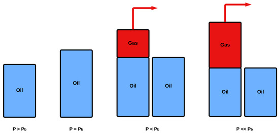
Figure 1.
Differential liberation (DL) experiment.
In addition to the measured data, several properties, directly applicable to reservoir engineering applications, can be extracted at all stages of the DL test by applying mathematical operations on the raw data [52,54]. These include the following:
- Differential oil formation volume factor ()
- is calculated by dividing the recorded oil volume () of the oil at the th pressure step by the residual oil volume ():
- Differential solution gas–oil ratio ()
- is obtained by dividing the total amount of gas released from the current pressure step down to the atmospheric one (cumulative gas) at standard conditions by the volume of the residual oil ():Note that the subscript indicates the final stage of the DL test at atmospheric pressure and reservoir temperature.
- Oil specific gravity ()
- The oil specific gravity is the ratio of the equilibrium oil’s density at each pressure step to the density of water at 60 °F:where is determined from the measured density and volume of the residual oil. The moles of the gas, , removed at each step, along with the gas molecular weight, , typically in the form of its specific gravity, , and the oil volume at each stage, are all measured and known.
- Compressibility factor ()
- The compressibility factor accounts for deviations of the released gas behavior from those of the ideal gas and can be determined by the real gas equation:where and are the pressure and temperature of the hydrocarbon system, is the volume of the liberated gas at and and , and correspond to standard conditions.
- From the compressibility factor, the gas formation volume factor () can be determined by definition as follows:
- Gas specific gravity ()
- The gas specific gravity is an indication of its weight and is used to compute the amount of mass released at each pressure step:where is the air molar mass, i.e., 28.97 g/mole.
To relate reservoir oil volumes to produced oil and gas volumes, the differential oil formation volume factor () and solution gas–oil ratio () are converted to a stock-tank-oil basis according to Equations (7) and (8) [55].
where and denote the oil formation volume factor and the solution gas–oil ratio at saturation point, respectively, as determined from a multi-stage separation test (MSST). and are the differential volume factor and solution gas–oil ratio at saturation point. Note that reflects how much the oil volume expands at reservoir pressure compared to its volume under standard conditions, whereas is a measure of how much dissolved gas comes out of the oil at a specific pressure.
3. Quality Control of the DL Study Results
To apply quality control (QC) on the differential liberation (DL) study results, one may proceed by considering two major aspects. The first one is related to the mass and mole balance of the products obtained at each pressure step by means of the delivered PVT data, i.e., oil and gas phase properties. This step can be thought of as the inverse calculation of what is supposed to have already been conducted at the lab. Indeed, mass balance is already incorporated in Equation (3), where the oil mass at step is assumed to equal to the sum of the oil and gas masses obtained at the next step, i.e., . Clearly, if mass balance has been honored in the forward calculations, this should also guarantee its validity in the inverse calculations as well [55].
The second aspect is related to the consistency and quality of the gas compositions obtained at each pressure step, their validity and consistency to the rules governing such compositions. In other words, in this aspect, we focus to the distribution of the gas to individual components rather than only relying on its total mass balance. Both aspects require that various variables, not delivered in the DL report, need to be calculated. Those values can be calculated using equations derived from the principle of conservation of mass and are further applied to a series of fluids with varying volatility. Subsequently, QC can be conducted on those results to determine whether they are consistent or not.
3.1. Total Mass Balance
The primary objective of applying the total mass balance equation is to estimate the density of the residual oil at the end of the DL experiment and compare it to the reported value. If no such value is available, the residual oil density can be evaluated for its physical soundness. In fact, the density of the residual oil is expected to be higher than that of the stock tank oil (STO) obtained after flashing the reservoir fluid to atmospheric conditions through the production separator train. This is due to the fact that the DL study is run in many steps at the reservoir temperature, i.e., at an elevated one, compared to the multi-stage separation test (MSST). On the other hand, during the oil production to atmospheric conditions, the procedure is run in a limited number of separation steps, allowing for some gas to stay dissolved in the produced crude. As a result, more gas is expected to be liberated in the DL test compared to the separator test, thus forcing an increasing residual oil density. When dealing with more volatile oil samples, the difference between these two density measurements is more pronounced, attributable to the higher quantity of dissolved gas present in these samples. Conversely, in the case of heavier oil samples characterized by a lower quantity of dissolved gas, the two density measures tend to converge, resulting in closer calculated values.
By writing down the mass conservation principle, Equation (9) is obtained, in which stands for the pressure step. This equation asserts that the mass of the sample at the bubble point () equals the sum of the gas mass liberated at each pressure step () and the oil residual mass () received at the final step. The objective is to transform Equation (9) by implementing appropriate formulae based on volumetric data and eliminating the mass terms.
Equations (10)–(12) are used, where and are the oil density and volume at saturation pressure, and stand for the number of gas moles and their molar mass and and denote the density and volume of the residual oil:
By replacing Equations (9)–(11) with Equations (8) and (12), the following is obtained:
Subsequently, , and are replaced by Equations (14)–(16), respectively, where represents the oil formation volume factor at the bubble point pressure, stands for the gas volume received at each pressure step at standard conditions and is the gas molar volume at standard conditions. is the solution gas-to-oil ratio and denotes the liberated gas specific gravity.
By simplifying and solving the final expression for , the residual oil density is obtained by Equation (17):
3.2. Mass Balance per Pressure Step
Setting up a mass balance equation per pressure step bears similarity to the total mass one discussed in the previous section. However, the key distinction lies in the scope of analysis: while the previous equations examined mass balance from the bubble point to the atmospheric pressure, the individual pressure step equations evaluate the conservation of mass at each step of the DL study. Replicating the previous approach, the same equation is initiated, resulting in a paired equation set, which is employed for every step of the study. The equality of the two components of the final equation should persist across each pressure step, as any significant deviation indicates a disruption in the mass conservation.
In this context, Equation (9) is reformulated in Equation (18) and applied to each specific pressure step. Equation (18) indicates that the oil mass at each step equals the combined mass of the liberated gas and the remaining oil:
By applying similar transformations to those of the previous section, the final equation (Equation (19)) is obtained:
By applying Equation (19) using the PVT values at each pressure step, both sides of the equation are anticipated to be equal, thereby ensuring a comprehensive mass balance assessment.
3.3. Component Mass Balance per Pressure Step
In this phase of the QC process, mass balance equations are used to calculate the composition of the remaining oil at each step of the DL study. The molecular composition of the fluid under reservoir conditions, which equals the fluid’s composition at the start of the DL study, along with the molecular composition of the gas released at each stage of the study are both available in the PVT report and are used in the calculations.
Once the oil compositions have been determined, they are plotted on a diagram for each pressure step and for each component. The changes in composition for each pressure value are observed, and any deviations from the expected behavior are analyzed. Under normal circumstances, with decreasing pressure, gas components should show decreasing concentrations, while the heavier oil components should exhibit increasing concentrations. When the pressure reaches the atmospheric level, the concentration of methane and other light components should be very close to zero. Moreover, the residual liquid composition can also be compared to the composition of the flashed liquid, readily accessible in the PVT report. As elucidated in Section 3.1, it is anticipated that the residual oil extracted from the DL study will exhibit a heavier composition compared to its flashed counterpart.
Similarly to the previous approach, the deduction is initiated from Equation (20), which is also based on the principle of mass conservation. This equation asserts that for each component , the total moles present in the sample equate to the sum of its moles in the gas phase and those in the remaining oil phase. Through a series of transformations, the ultimate expression is ultimately reached once again. Starting from
the mole expressions can be reformulated as the product of the total moles of each sample multiplied with the molar fraction of each component ( in the liquid phase and in the gas phase).
The moles of the oil constituents can be subsequently substituted with Equation (22) and the result of these substitutions is shown in Equation (23).
The molecular weight of the oil sample at each pressure step can be computed by multiplying the sum of its oil component’s concentrations and of the sum of their individual molecular weights. The molecular weight of the oil sample in the next pressure step (), however, cannot be computed in the same way; therefore, it should be computed with Equation (24).
In the following step, by applying similar transformations as those performed in Section 3.1, Equation (25) is ultimately reached.
By solving Equation (25) for and further on simplifying the resulting one, the final expression, Equation (27), is obtained:
where A = and B = .
By solving Equation (27) for at each pressure step and for each component j, the equilibrium oil’s composition is determined in terms of molecular fractions of the components.
3.4. k-Values Distribution and Consistency
The final step of the QC process involves the calculation of the equilibrium coefficients (k-values) for each component at every pressure step. k-values, which represent the equilibrium constants of individual components between the gas and oil phases at the equilibrium conditions, are calculated with the use of Equation (28) [54,56,57]. In Equation (28), represents the k-value of component j at pressure step i of the DL study. Similarly, and stand for the concentration of the liberated gas phase and of the remaining oil phase. The values of were calculated using the method described in Section 3.3.
Individual k-values are expected to tend towards unity at high pressures, specifically as the pressure approaches the convergence one.
In addition, plots contrasting the values of for each pressure step against the values are generated. s, calculated from Equation (29), remain constant across all pressure steps, while represents the logarithm multiplied with the pressure at each step. Note that, in Equation (29), and represent the boiling point and the critical temperature of component , whereas represents the reservoir temperature.
According to Hoffman et al. [56,58], when it comes to hydrocarbon components ranging from C1 to C6, the plot of exhibits a linear trend at all pressures. In addition, lighter components of the C1 to C6 range exhibit higher values due to their higher concentrations in the liberated gas phase. These plots need to be generated independently for each sample and for each pressure step of the DL study, comparing the values of the of hydrocarbon components C1–C6 with the constant values of the same components. As previously mentioned, the plot of is expected to exhibit a linear trend at all pressure steps, with the values decreasing for heavier components [56,58].
Finally, a combined plot of can be created, integrating all pressure steps into a single diagram. Since the values of remain constant in all pressure steps, the combined plot is expected to effectively illustrate the diverse trends of on the y-axis in relation to the values of displayed on the x-axis. According to Hoffman et al., the values of are expected to converge at a common point with increasing values of [56,58].
4. Analysis of Differential Liberation (DL) Test Results
The workflow discussed in Section 3 is based on the mass balance principle and can determine the quality of oil samples of very low or very high volatility. To illustrate this capability, the workflow was applied to four reservoir fluids of varying volatility, selected from an in-house database, to identify whether the differential liberation (DL) test results are indeed plagued by issues and to conclude on the extent of their trustworthiness. Due to error propagation, caused at the lab, issues are expected to be more pronounced in the final steps of the test, with the first steps showing more consistent behavior. The results obtained are demonstrated using four example fluids, two volatile oils and two low-volatility ones.
The PVT data and the reservoir fluid composition of all four samples are shown in Table 1 and Table 2. All PVT properties shown in Table 1 are at saturation pressure and in SI units. As can be seen from the samples’ properties and composition, reservoir fluids 1 and 2 are volatile, whereas fluids 3 and 4 exhibit low volatility.

Table 1.
PVT properties of the four oil samples.

Table 2.
Composition of the four oil samples.
4.1. Results of Total Mass Balance
The total mass balance quality control (QC) is conducted using Equation (17) and the resulting residual oil densities are shown in Table 3, alongside the measured stock tank oil (STO) densities. All density values are in SI units. As mentioned in Section 3.1, the residual densities are anticipated to be higher than those of the stock tank oil and those differences are expected to be more pronounced in fluids with higher volatility.

Table 3.
Total mass balance results.
From Table 3, it is verified that the residual oil densities are higher than the stock tank ones. This difference is relatively lower in reservoir fluids 3 and 4, which are the low-volatility fluids, and is especially lower in reservoir fluid 3, which is the least volatile. This is further confirmed in Figure 2, where the residual oil density is plotted against the stock tank oil one and the trendline clearly indicates that the higher the volatility of oil (i.e., the lower its residual oil density), the higher the difference between that and its stock tank oil counterpart. Therefore, the total mass balance results appear reasonable and consistent with the expected behavior in all four samples tested.
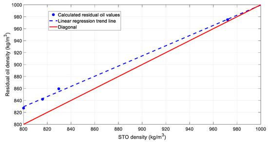
Figure 2.
Visual comparison between the calculated residual oil density and the stock tank oil (STO) one.
4.2. Results of Mass Balance by Pressure Step
As shown in Section 3.2, the pressure step mass balance quality control is conducted using Equation (19). The two parts of the equation are expected to be equal for each pressure step to honor the mass conservation. The results, along with the deviation error of the equations, are presented in Table 4, Table 5, Table 6 and Table 7. In the far-left column, the pressure steps of the DL study for each reservoir fluid are shown in MPa.
4.2.1. Reservoir Fluid 1
The results for reservoir fluid 1 are shown in Table 4:

Table 4.
Pressure step mass balance results for reservoir fluid 1.
Table 4.
Pressure step mass balance results for reservoir fluid 1.
| Pressure Step (MPa) | (Rs,i − Rs,i+1) + ρo,i+1Bo,i+1 | Deviation (%) | |
|---|---|---|---|
| 31.2–27.6 | 1212.38 | 1211.64 | 0.06 |
| 27.6–21.6 | 1136.83 | 1148.37 | 1.01 |
| 21.6–15.6 | 1062.55 | 1062.99 | 0.04 |
| 15.6–9.6 | 1008.29 | 1006.11 | 0.22 |
| 9.6–3.6 | 963.83 | 964.85 | 0.11 |
| 3.6–0.1 | 918.33 | 861.53 | 6.38 |
As can be seen in Table 4, the two parts of Equation (19) are very close in most steps, exhibiting a deviation error of less than 1%. However, in the last pressure step, significant deviation appears, confirming that issues are indeed more pronounced at the last steps of a DL study.
4.2.2. Reservoir Fluid 2
The results for reservoir fluid 2 are shown in Table 5:

Table 5.
Pressure step mass balance results for reservoir fluid 2.
Table 5.
Pressure step mass balance results for reservoir fluid 2.
| Pressure Step (MPa) | (Rs,i − Rs,i+1) + ρo,i+1Bo,i+1 | Deviation (%) | |
|---|---|---|---|
| 21–18 | 1114.22 | 1114.77 | 0.05 |
| 18–14.6 | 1084.30 | 1084.34 | 0.00 |
| 14.6–11.1 | 1053.45 | 1053.55 | 0.01 |
| 11.1–7.7 | 1026.41 | 1026.31 | 0.01 |
| 7.7–3.9 | 1001.49 | 998.11 | 0.34 |
| 3.9–0.1 | 969.75 | 903.47 | 7.08 |
Similarly to the results of the previous fluid, the difference between the two parts of Equation (19) is more pronounced in the last step of the DL study, although that in the previous steps is a bit lower than that of the first sample.
4.2.3. Reservoir Fluid 3
The results for reservoir fluid 3 are shown in Table 6:

Table 6.
Pressure step mass balance results for reservoir fluid 3.
Table 6.
Pressure step mass balance results for reservoir fluid 3.
| Pressure Step (MPa) | (Rs,i − Rs,i+1) + ρo,i+1Bo,i+1 | Deviation (%) | |
|---|---|---|---|
| 9.3–7.5 | 1008.56 | 1009.18 | 0.06 |
| 7.5–5.7 | 1003.91 | 1002.92 | 0.10 |
| 5.7–2.9 | 999.59 | 998.50 | 0.11 |
| 2.9–1.3 | 992.84 | 994.15 | 0.13 |
| 1.3–0.1 | 988.19 | 980.78 | 0.75 |
The results of reservoir fluid 3 in Table 6 are much better than those of the two previous fluids. In all steps of the DL study, the deviation error between the two parts of the Equation is less than 1%, which further goes on to confirm that lower-volatility fluids generally tend to show less errors in the quality control process.
4.2.4. Reservoir Fluid 4
The results for reservoir fluid 4 are shown in Table 7:

Table 7.
Pressure step mass balance results for reservoir fluid 4.
Table 7.
Pressure step mass balance results for reservoir fluid 4.
| Pressure Step (MPa) | (Rs,i − Rs,i+1) + ρo,i+1Bo,i+1 | Deviation (%) | |
|---|---|---|---|
| 12.1–11 | 1199.58 | 1200.16 | 0.05 |
| 11–8.7 | 1180.06 | 1179.60 | 0.04 |
| 8.7–6.7 | 1141.16 | 1140.92 | 0.02 |
| 6.7–4.4 | 1110.33 | 1109.94 | 0.03 |
| 4.4–2.5 | 1077.73 | 1071.66 | 0.56 |
| 2.5–0.1 | 1036.61 | 928.45 | 11.01 |
From Table 7, it can be seen that the results of reservoir fluid 4 show significant errors in the last step of the DL study, where an error of 11.01% is the highest one observed out of all four fluids. This fact goes to show that even in lower-volatility fluids, there are errors that could potentially cause problems after their utilization by engineers, highlighting that caution should always be taken, regardless of the sample’s characteristics.
4.3. Results of Component Mass Balance by Pressure Step
In the final part of the QC process, the results of component mass balance by pressure step, as well as the results of the k-values, are analyzed for each fluid. As mentioned above, this part of the quality control is conducted using Equations (27)–(29).
4.3.1. Reservoir Fluid 1
The DL data of reservoir fluid 1, which was a volatile oil, were tested first.
Figure 3 demonstrates the calculated saturated oil’s composition at all six different DL steps, together with that of the residual oil. As expected, with each subsequent step, the calculated composition is heavier compared to that at the previous step. The volatile components, especially methane, are being liberated at each step, with the final one showing C1 mole% concentration practically equal to zero. Subsequently, with each step, the plus fraction (Cn+) mole% concentration increases, which is in line with the expected residual oil behavior during a DL test.
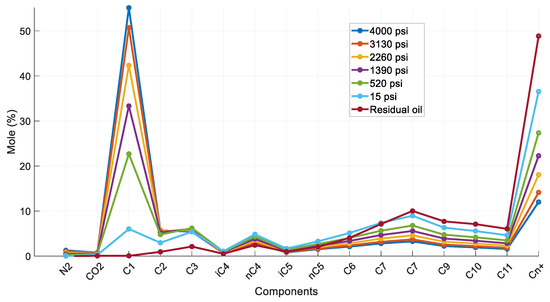
Figure 3.
Composition of reservoir oil and saturated oil at each DL step (reservoir fluid 1).
To further investigate the accuracy of the results, the k-values for each component were studied. Figure 4 compares the (log) k-values vs. pressure plots created for each of component at 223.3 °F against the typical behavior of the k-values vs. pressure plot at 200 °F, as prepared by Katz and Hachmuth from experimental data [59,60]. Note that slight deviations between the reservoir fluid k-values and those obtained from the representative plots are expected to be there since k-values are a function of the fluid composition rather than the individual components, pressure and temperature solely. Therefore, an average shape match rather than an exact match is expected. The k-value plots in Figure 4a match those presented in Figure 4b and seem to converge at a point close to 5000 psia (convergence pressure), which is in consistency with the representative plots.
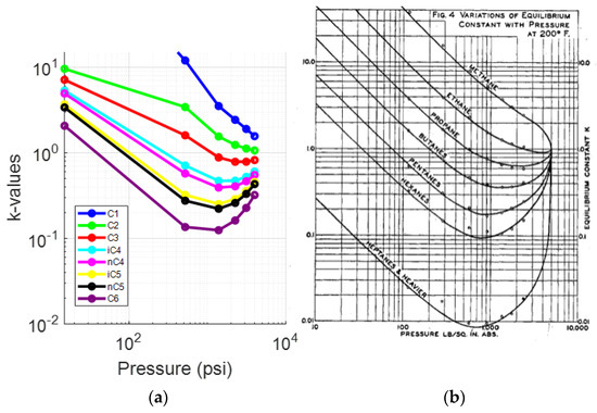
Figure 4.
(a) k-values vs. pressure plot of the saturated oil at each DL test step (reservoir fluid 1); (b) typical oil k-value vs. pressure plot at 200 °F [59].
A deviation of the light components (up to propane) can be seen from the fourth step (1390 psia) onwards, while the rest of the components, and especially C6, behave in a manner that resembles the representative plots much more closely. This is clear when comparing the k-value plots for C1 (Figure 5a) and C6 (Figure 6a) at 223.3 °F against their representative plots of the corresponding single components for different temperatures, as proposed by NGAA [59,61] (Figure 5b and Figure 6b respectively). The reservoir fluid’s C1 plot, up to the fourth step, does not match the curve close to 200°F as, from the fifth step (520 psia) and onwards, it is clearly deviating from the norm. In contrast, the reservoir fluid’s C6 plot is almost an exact match at 220 °F.
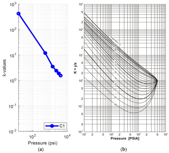
Figure 5.
(a) k-values vs. pressure plot of the saturated oil’s methane at each DL step at 223 °F (reservoir fluid 1); (b) methane k-value vs. pressure plot at different temperatures [59].
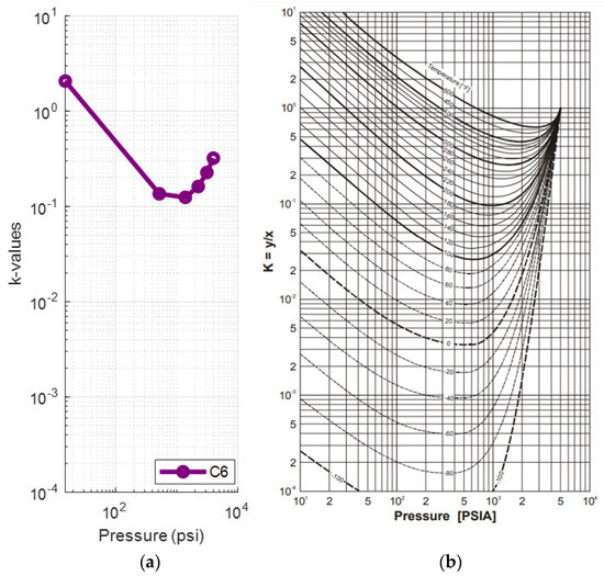
Figure 6.
(a) k-values vs. pressure plot of the saturated oil’s hexane at each DL step at 223 °F (reservoir fluid 1); (b) hexane k-value vs. pressure plot at different temperatures [59].
Summarizing, the shape of the curves regarding pressure is fully realistic and deviations from typical charts must be attributed only to the compositional effects. Although lighter components are more prone to deviations at each liberation step, compared to the heavier ones, pointing out that the error propagation is significant with each subsequent step, the natural k-values structure is still pertained.
The Hoffman plots of the obtained k-values at each pressure step are shown in Figure 7. The typically expected behavior is verified, as described in Section 3.4, with all plots exhibiting a sufficiently linear shape and converging to a single point, the same way the k-values themselves do at the convergence pressure. Divergence is observed at the final step (15 psia) of the DL, indicating an underlying issue with the last flash at atmospheric pressure. To further investigate this, a comparison of the residual oil’s composition against that of the stock tank oil was examined. Indeed, the composition of the residual oil collected at the final step must exhibit higher heavy end concentration compared to that of the STO since more gas should normally be liberated during a DL test compared to a flash test. Although this is fairly validated from Figure 8, the residual oil C4- mole% is still slightly higher than that of the STO, indicating a more volatile fluid, contradicting lab experience.
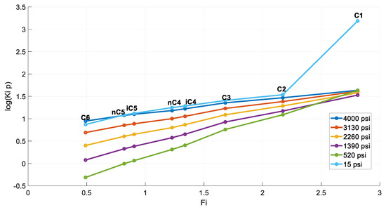
Figure 7.
Hoffman plots at each DL step (reservoir fluid 1).
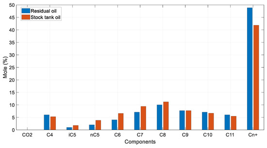
Figure 8.
Residual oil vs. STO mole % compositions (reservoir fluid 1).
Summarizing, the test results for this volatile oil sample were found to be fully acceptable for the first steps of the DL test. However, caution should be advised when interpreting the final steps, as slight divergences from typical behavior regarding the Hoffman plot and the k-values plot may appear, as well as inconsistency between the residual oil and the STO’s compositions. Clearly, this is attributed to the fact that the greater the steps, the higher the error accumulation, which may lead to unsound results, as is demonstrated in the following fluid examples.
4.3.2. Reservoir Fluid 2
The second fluid tested is reservoir fluid 2, which is a light oil sample.
Figure 9 illustrates the calculated saturated oil’s composition for each of the six DL pressure steps, along with that of the residual oil. Until the fifth step (565 psia), the fluid demonstrates the typical behavior of the lighter components being liberated, with the heavier components’ concentration increasing with each subsequent pressure drop. However, at the fifth step, C1 mole% concentration becomes practically equal to zero, and at the final step, it obtains an entirely unrealistic negative value. Additionally, the composition of C7 diverges from the trend of the previous steps, and although it should be increasing with each subsequent pressure reduction, in the final step, its composition drops below that of the fourth step (1115 psia). Contrary to the previous volatile sample’s acceptable behavior, this sample’s composition results are erratic.
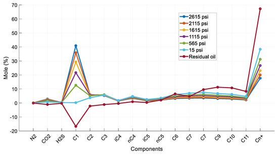
Figure 9.
Composition of reservoir oil and saturated oil at each DL step (reservoir fluid 2).
The issues beyond the fourth step are also evident in Figure 10a when calculating the k-values. Methane deviates significantly from the representative k-values vs. pressure plots at 200 °F (Figure 10b) after the fourth step (1115 psia). Note that the final step of flashing to atmosphere was not plotted due to methane, ethane, propane and i-butane exhibiting calculated negative k-values. The fluid’s behavior up to the fourth step matches that from Katz and Hachmuth’s study. A closer comparison of the plots down to the fourth step (Figure 10a) against the experimental data of light crude oil at 250 °F (Figure 10b) confirms that reservoir fluid 2 behaves similarly to the experimental data from Standing and Katz [59,62].
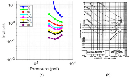
Figure 10.
(a) k-values vs. pressure plot of the saturated oil at each DL test step (reservoir fluid 2); (b) typical oil k-value vs. pressure plot at 250 °F on a log–log scale from Katz and Hachmuth and from experimental data using light crude oil from Standing and Katz [59].
Contrary to the previous volatile reservoir fluid, presented at Section 4.3.1, the results of this fluid can be trusted only up to the fourth step as the next steps exhibit severe deviations from the ideal norm and the final step is plagued by negative k-values for several components, eliminating the need to study the Hoffman plot. Coupled with the negative composition of C1 in the residual oil, this concludes in a highly unrealistic test result.
4.3.3. Reservoir Fluid 3
To examine the possible issues faced when analyzing the DL results of a low-volatility oil, reservoir fluid 3 was studied next.
Figure 11 illustrates the saturated oil’s composition at all five DL steps. This sample behaves similarly to the volatile oil in Section 4.3.1. Regardless of its particularly low volatility, this oil exhibits typical behavior during the DL test, where the saturated oil composition becomes heavier at each next step and with the residual oil being the heaviest. Furthermore, C1 concentration gradually declines to zero at the residual oil and the heavy end’s composition increases as more gas is being liberated from the fluid, as naturally expected.
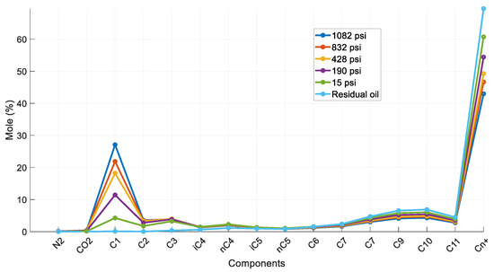
Figure 11.
Composition of reservoir oil and saturated oil at each DL step (reservoir fluid 3).
Further analysis of the k-values was performed to determine the reliability of their values by comparing their plot vs. pressure at reservoir temperature (Figure 12a) against the generic behavior at 120 °F and at 200 °F, as proposed by Katz and Hachmuth [59,60] (Figure 12b,c). The comparison shows that the reservoir fluid’s k-value plots at 170 °F do fall between the representative plots at 120 °F and at 200°F, except C2, which exhibits minor divergence at the final step. A closer comparison the k-values of C1 (Figure 13a) against the representative individual component plot proposed by NGAA [59,61] (Figure 13b) verifies that the reservoir fluid’s plot matches well between the proposed plots of 100 °F and 200 °F up to the fourth step (190 psia). For hexane (Figure 14a,b), the DL k-values match almost exactly the representative plot at 170 °F. This behavior is consistent with that of the volatile oil presented in Section 4.3.1, pointing to issues being more prominent at the final steps and especially at the lighter components. In fact, the resemblance between the computed k-values and the reference ones of the individual components is more pronounced. This is attributed to the fact that this fluid is heavier than reservoir fluid 1; hence, the DL path conditions lie far away from the critical point, thus further weakening the compositional effects.
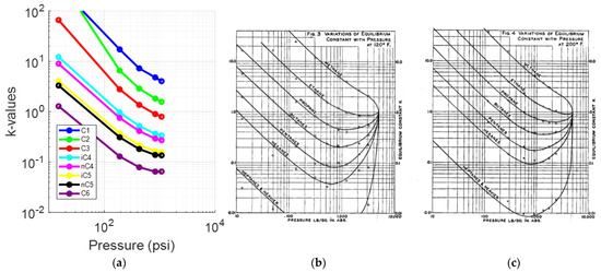
Figure 12.
(a) k-values vs. pressure plot of the saturated oil at each DL test step (reservoir fluid 3); (b) typical oil k-value vs. pressure plot at 120 °F; (c) typical oil k-value vs. pressure plot at 200 °F [59].
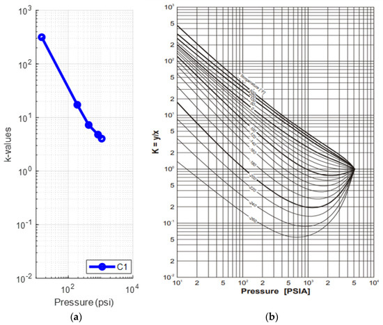
Figure 13.
(a) k-values vs. pressure plot of the saturated oil’s methane at each DL step at 170 °F (reservoir fluid 3); (b) methane k-value vs. pressure plot at different temperatures [59].
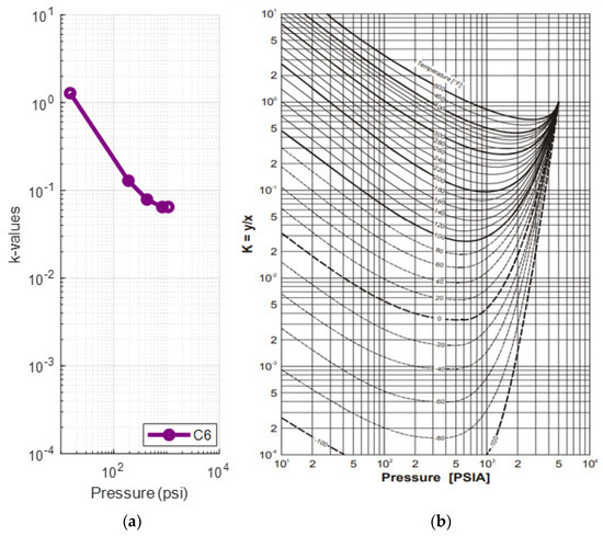
Figure 14.
(a) k-values vs. pressure plot of the saturated oil’s methane at each DL step at 170 °F (reservoir fluid 3); (b) hexane k-value vs. pressure plot at different temperatures [59].
The inspection of the Hoffman plots (Figure 15) reveals again that the resulting compositions can be trusted for the first steps of the test while being questionable only at the last step. However, contrary to the volatile sample presented in Section 4.3.1, for this oil, the curves for all pressure steps converge at C1, as per the Hoffman plot standard. The C2 and C3 abnormalities could potentially be attributed to data smoothing or digitization errors.
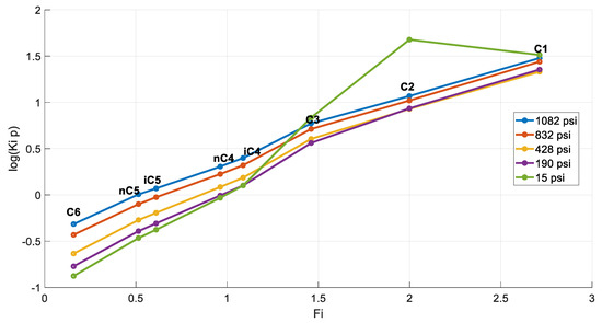
Figure 15.
Hoffman plots at each DL step (reservoir fluid 3).
The composition of the residual oil is expected to exhibit a higher heavy end concentration compared to that of the stock tank oil since more gas is normally liberated during a DL test compared to a flash test. This is validated in Figure 16, as is the case with reservoir fluid 1. Moreover, the residual oil C4- mole% is slightly lower than that of the STO, indicating a heavier fluid, thus validating physics experience. It further demonstrates that there is less error in the DL analysis when studying lower-volatility samples, possibly due to fewer steps needed for the test and less gas being liberated from the saturated oil sample at each step.
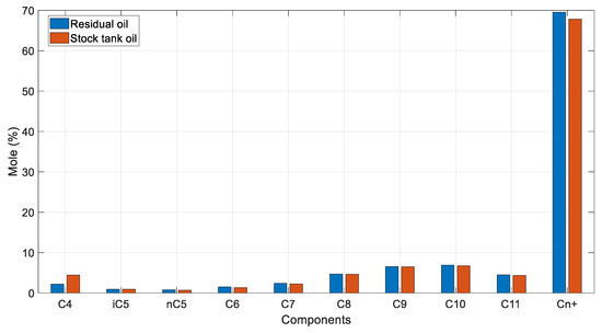
Figure 16.
Residual oil vs. STO mole % compositions (reservoir Fluid 3).
Summarizing, the test results for this low-volatility oil sample are found to be acceptable and more trustworthy than those of the volatile samples analyzed in Section 4.1 and Section 4.2, though caution is still advised, as this does present some issues at the final step, as indicated by the k-values vs. pressure and the Hoffman plots.
4.3.4. Reservoir Fluid 4
To check the hypothesis that the DL test results are always consistent when considering low-volatility oil samples, reservoir fluid 4 was further examined.
Similarly to the results obtained in Section 4.3.3, this sample exhibits saturated oil composition behavior (Figure 17) which resembles the normal one, with a decreasing concentration of the lighter components and an increasing one for the heavier components with each subsequent pressure depletion step.
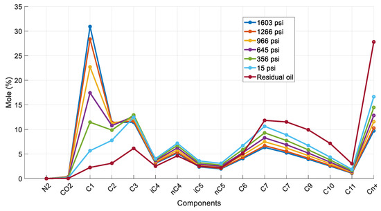
Figure 17.
Composition of reservoir oil and saturated oil at each DL step (reservoir fluid 4).
By comparing the k-values (Figure 18a) against the representative ones at 120 °F and at 200 °F (Figure 18b,c) by Katz and Hachmuth [59,62], the expected behavior is observed only up to the fifth pressure step (356 psia). The final step (15 psia) is plagued by issues, evident by the divergence of all components but C6 from their individual component plots. A closer analysis of the k-values plot of C6 (Figure 19a) reveals that when compared to the representative plot for 170 °F (Figure 19b), it follows the typical behavior again up to the fifth step and then diverges from it.
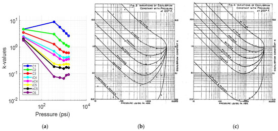
Figure 18.
(a) k-values vs. pressure plot of the saturated oil at each DL test step (reservoir fluid 4); (b) typical oil k-value vs. pressure plot at 120 °F [59]; (c) typical oil k-value vs. pressure plot at 200 °F [59].
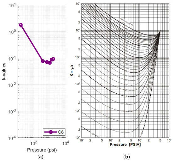
Figure 19.
(a) k-values vs. pressure plot of the saturated oil’s methane at each DL step at 171.4 °F (reservoir fluid 4); (b) hexane k-value vs. pressure plot at different temperatures [59].
The abnormal k-values at the final step has an effect on the fluid’s Hoffman plots. Indeed, Figure 20 points to a problem with the curve of the final step. Nevertheless, contrary to the volatile samples, the problematic Hoffman plot for the final step of this heavy oil maintains the ideal line, albeit not converging to C1.
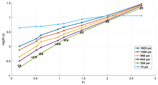
Figure 20.
Hoffman plots at each DL step (reservoir fluid 4).
The issue at hand is more prominent when comparing the mole% composition of the residual oil against the mole % composition of the STO (Figure 21). While the composition of the plus fraction component is practically same, the heavy components of the residual oil exhibit an unnaturally low concentration compared to the STO. Similarly, the light components’ concentration in the residual oil is higher than their STO counterparts. This is even more evident when comparing the residual oil’s C4- mole% (18%) vs. the STO’s one (5%).
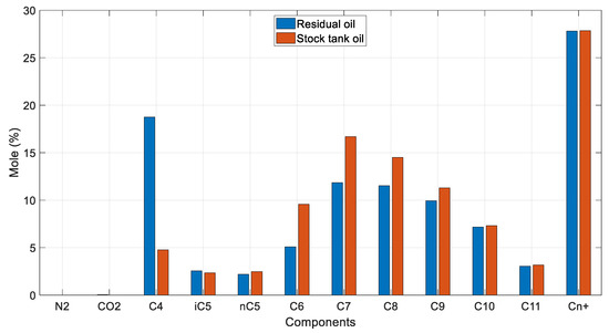
Figure 21.
Residual oil vs. STO mole % compositions (reservoir fluid 4).
The obtained results, while more realistic compared to those of the questionable volatile oil in Section 4.3.2 that exhibits negative C1 composition, are still irregular. The residual oil should be heavier than the STO, as more gas is liberated from it. This, in conjunction with the issues revealed from the k-values vs. pressure plots, indicate that although the low-volatility oils’ DL test results do have a better chance of being reasonable, compared to those of volatile oils, caution should still be taken when interpreting them, especially regarding the low-pressure steps.
5. Discussion
The analysis of the DL test results for the selected oil samples highlights significant concerns regarding their reliability and accuracy. The study performed covered a wide range of oil volatility and revealed that while DL tests are a fundamental component of a PVT analysis, their results must be examined thoroughly before been utilized in reservoir engineering calculations.
The total mass balance study produced physically sound and reasonable results, regardless of the test fluid volatility, as far as the comparison between the density of the residual oil and that of the stock tank oil (STO) is concerned. Note that the residual oil density can be (indirectly) measured and should appear in every PVT study. However, PVT labs often skip this value to avoid quantitative check calculations and only allow for a rough qualitative test.
On the other hand, the pressure step mass balance results indicated various levels of divergence on the last steps of the process. The deviations were found to be more significant on high-volatile samples. The analysis confirms the previously mentioned findings and shows that the first steps of the test for both volatile and heavy oils are physically sound and can be trusted in general. However, caution is advised regarding the resulting oil composition at the final steps and especially that of the residual oil.
The findings indicate that volatile oils present greater difficulties in DL tests. The sample’s unrealistic results, presented in Section 4.3.2, underline the challenges of accurately capturing gas liberation and compositional changes due to the rapid and dynamic nature of the volatile oil’s behavior under pressure depletion. This is especially evident in the last step of the test, where the residual oil often ends with a negative mole% methane concentration. Even the volatile sample in Section 4.3.1, which demonstrated more acceptable results, exhibited inconsistencies that warrant caution, especially when comparing the composition of its residual oil to that of the stock tank oil. This variability could be attributed to the enhanced sensitivity of the volatile oils, especially near-critical ones, to minor errors in lab measurements and data handling, as well as the inherent complexities related to their volatility and the potential failure to maintain thermodynamic equilibrium.
Low-volatility oils exhibit more consistent and reliable test outcomes. The sample presented in Section 4.3.4, though acceptable in general, still raises the need for careful interpretation to avoid potential fluid modeling risks. On the other hand, the sample presented in Section 4.3.3, while exhibiting unrealistic behavior in the last steps, is found to be far less problematic compared to its volatile counterpart. The lower gas liberation rates and more stable properties of the low-volatility oils seem to contribute to fewer measurement errors and more trustworthy results. In addition to these, the saturation pressure of typical black oil is significantly lower than that of a volatile fluid. Consequently, fewer pressure steps are required to reach surface conditions, implying less measurements and a decreased risk of measurement errors. This is particularly important because measurement errors, in this context, are mostly systematic rather than random. These errors tend to accumulate rather than cancel out as pressure decreases towards atmospheric levels.
During this study, it was identified that the DL tests seem to be challenged by inaccuracies in GC gas composition measurements, with potential data processing errors and equipment calibration issues being evident as well. These problems highlight the need for extensive quality control (QC) procedures to take place across every step of the process. The necessity for rigorous QC is even more intense when dealing with volatile oils due to the potentially physically unsound results. Engineers should implement thorough QC checks and must validate the results though cross-checking with other PVT data, or even with historical data of the same well and field, if available, to ensure increased accuracy. In the case where discrepancies are detected, they could consider applying corrections to the affected data or even repeating the PVT experiment. Such manipulations can be applied mathematically to estimate the least possible modification which is needed to be applied to the liberated gas composition to honor all mass balance checks. By applying these measures, engineers can enhance the reliability of their fluid models and reservoir simulations, which in turn can lead to more informed and safer field management decisions.
The quality control methodology for DL PVT data developed in this work operates solely as a post-test analysis tool rather than a real-time QC tool. This is because the values for differential oil formation volume factor (Bo), differential solution gas–oil ratio (Rs), oil density (ρo) and gas specific gravity (γg) required for the material balance equation cannot be determined until the DL test is completed and the density of the stock tank oil is obtained, which is only defined at the final stage of the test. Consequently, the mass balance cannot be applied during the DL test to identify errors early; it can only be utilized once the test is complete. Once the raw measurements have been converted to PVT data through mathematical manipulations, the quality control procedures outlined in our study can be conducted. If quality control identifies unreliable PVT data at specific pressure steps, two solutions are possible: either repeating the test, which is both time consuming and expensive, or computationally correcting the volumes at these steps to ensure that the material balance is satisfied.
Future research could broaden the scope of this study by developing a data analysis technique that addresses measurement errors computationally. This technique would aim to identify the minimum adjustments to measured values needed to ensure all mass balances within the system are satisfied. Given the redundancy in the system (more unknowns than equations), the problem is inherently ill posed. However, incorporating specific constraints into the optimization problem could lead to a robust solution. One example may be implementing a weighting scheme that prioritizes adjustments to measurements from lower-pressure steps, where errors are known to be more prominent. Additionally, the framework could be expanded to incorporate other types of process constraints, leading to a more robust error mitigation strategy. This approach has the potential to significantly improve data analysis accuracy and reliability in various fields. By computationally accounting for measurement errors while maintaining mass balance integrity, researchers can extract more reliable information from their experiments.
6. Conclusions
The methodology for quality checking the results of a typical DL test analysis through mass balance verification was demonstrated on a selection of fluid samples with varying volatility. The comprehensive study that was conducted revealed some critical insights into the accuracy and reliability of the reported results. It further indicated that there was a general concern regarding the results of the DL test. While generally the results of the first steps can be trusted and considered rather safe, the later steps and especially the final step result in unreliable data. Volatile oils demonstrate more significant inconsistencies than their heavier counterparts. These inconsistencies, such as the unrealistic negative concentration of light components, highlight the challenges of properly and accurately capturing the composition of liberated gas and the compositional changes in each step.
Low-volatility oils exhibit more consistent and reliable results. The less intense gas liberation contributes to less error accumulation during subsequent pressure steps. However, issues may appear at the later steps, and although less severe than those in the volatile oils, the final step was still maybe plagued by inconsistency.
The study manages to underline the necessity for extensive and rigorous quality control (QC) procedures at every step of the DL process, especially for volatile oil, and engineers should not rely solely on DL results without performing checks and applying corrections when and if needed. Potential inaccuracy in gas composition measurements, data processing errors, equipment calibration or simply human errors are possible factors of error and could lead to highly inaccurate data, which could damage the performance and the accuracy of an EoS model, that of a reservoir simulation, as well as that of machine learning model developments based on these data. The proposed workflow for validating PVT data can be integrated into standard industrial procedures, ensuring that only quality-controlled data are used for field development and operational planning.
In future work, the developed workflow can be extended to the quality check of multi-stage separation tests (MSSTs) and constant volume depletion (CVD) PVT results. Step mass balance control can be applied to both sets of experimental PVT data, whereas the total mass balance cannot be applied to the CVD data as the residual fluid is discarded.
Author Contributions
Conceptualization, P.P., S.L. and V.G.; methodology, P.P. and V.G.; validation P.P., S.L. and V.G.; writing—original draft preparation, P.P., S.L. and E.M.K.; writing—review and editing, V.G.; visualization, E.M.K. All authors have read and agreed to the published version of the manuscript.
Funding
This research received no external funding.
Data Availability Statement
No new data were created.
Conflicts of Interest
The authors declare no conflicts of interest.
References
- Chierici, G.L. Principles of Petroleum Reservoir Engineering; Springer: Berlin/Heidelberg, Germany, 1995. [Google Scholar]
- Dandekar, A.Y. Petroleum Reservoir Rock and Fluid Properties; CRC Press: Boca Raton, FL, USA, 2006; ISBN 978-0-429-12498-3. [Google Scholar]
- Guan, D.; Qu, A.; Gao, P.; Fan, Q.; Li, Q.; Zhang, L.; Zhao, J.; Song, Y.; Yang, L. Improved Temperature Distribution upon Varying Gas Producing Channel in Gas Hydrate Reservoir: Insights from the Joule-Thomson Effect. Appl. Energy 2023, 348, 121542. [Google Scholar] [CrossRef]
- Primio, R.D.; Dieckmann, V.; Mills, N. PVT and Phase Behaviour Analysis in Petroleum Exploration. Org. Geochem. 1998, 29, 207. [Google Scholar] [CrossRef]
- Economides, M.J.; Hill, A.D.; Ehlig-Economides, C.; Zhu, D. Petroleum Production Systems, 2nd ed.; Prentice Hall: Hoboken, NJ, USA, 2013; ISBN 978-0-13-703158-0. [Google Scholar]
- Pedersen, K.S.; Fredenslund, A.; Thomassen, P. Properties of Oils and Natural Gases|PDF|Petroleum|Gases. Available online: https://www.scribd.com/document/339329455/K-S-Pedersen-Aage-Fredenslund-P-Thomassen-Properties-of-Oils-and-Natural-Gases (accessed on 7 June 2024).
- Burcik, E.J. Properties of Petroleum Reservoir Fluids; Wiley: Hoboken, NJ, USA, 1957. [Google Scholar]
- Cameron, J. Petroleum Reservoir Engineering; Syrawood Publishing House: New York, NY, USA, 2019. [Google Scholar]
- Amyx, J.W. Petroleum Reservoir Engineering; Dedini, M., Ed.; Callisto Reference: New York, NY, USA, 2019; ISBN 978-1-64116-093-3. [Google Scholar]
- Dodson, C.R.; Goodwill, D.; Mayer, E.H. Application of Laboratory PVT Data to Reservoir Engineering Problems. J. Pet. Technol. 1953, 5, 287–298. [Google Scholar] [CrossRef]
- Ahmed, T. Equations of State and PVT Analysis. In Equations of State and PVT Analysis; Elsevier: Amsterdam, The Netherlands, 2013; pp. 1–553. [Google Scholar]
- Gaganis, V.; Kourlianski, E.; Varotsis, N. An Accurate Method to Generate Composite PVT Data for Black Oil Simulation. J. Pet. Sci. Eng. 2017, 157, 1–13. [Google Scholar] [CrossRef]
- Carstensen, C.-M.; Kanstad, S.K. Modifying the Gas-Oil Ratio and Water Cut of a PVT Lookup Table Using Correlations for Fluid Volatility. Chem. Eng. Res. Des. 2024, 205, 188–206. [Google Scholar] [CrossRef]
- Kanakaki, E.M.; Gaganis, V. Automated Equations of State Tuning Workflow Using Global Optimization and Physical Constraints. Liquids 2024, 4, 261–277. [Google Scholar] [CrossRef]
- Wei, Y.S.; Sadus, R.J. Equations of State for the Calculation of Fluid-phase Equilibria. AIChE J. 2000, 46, 169–196. [Google Scholar] [CrossRef]
- Laing, L.; Shirai, S.; Rosli, K.; Talabi, O.; Fawzi, N. Comprehensive PVT Data Review, Fluid Characterization and Grouping Study for Block X in Sarawak, Malaysia. In Proceedings of the Offshore Technology Conference Asia, Kuala Lumpur, Malaysia, 22–25 March 2022. [Google Scholar]
- Angulo, R. EOS Workflows Uncertainties and Implications in Reservoir Modeling. In Proceedings of the SPE Reservoir Characterisation and Simulation Conference and Exhibition, Abu Dhabi, United Arab Emirates, 17–19 September 2019. [Google Scholar]
- Williams, J.M. Getting the Best Out of Fluid Samples. J. Pet. Technol. 1994, 46, 752. [Google Scholar] [CrossRef]
- Hendraningrat, L.; Salleh, I.K. Applied Novel Quality Check Method for PVT Data with High Impurities Using Various Samples from Malaysian Fields. In Proceedings of the Abu Dhabi International Petroleum Exhibition & Conference, Abu Dhabi, United Arab Emirates, 15–18 November 2021; OnePetro: Richardson, TX, USA, 2021. [Google Scholar]
- Terry, R.E.; Rogers, J.B.; Craft, B.C. Applied Petroleum Reservoir Engineering, 3rd ed.; Prentice Hall: Hoboken, NJ, USA, 2015; ISBN 978-0-13-315558-7. [Google Scholar]
- Paredes, J.; Perez, R.; Larez, C. Screening Criteria And Methodology For Quality Check And PVT Selection For Reservoir Studies. Proc.—SPE Annu. Tech. Conf. Exhib. 2014, 2, 1561–1580. [Google Scholar] [CrossRef]
- Bilal, Y.; Hays, W.; Sissel, M. Compositional Uncertainties in Laboratory PVT Data. In Proceedings of the ADIPEC, Abu Dhabi, United Arab Emirates, 31 October–3 November 2022. [Google Scholar]
- Baker, R.O.; Regier, C.; Sinclair, R. PVT Error Analysis for Material Balance Calculations. In Proceedings of the Canadian International Petroleum Conference, Calgary, Alberta, 10–12 June 2003; OnePetro: Richardson, TX, USA, 2003. [Google Scholar]
- Lawrence, J.J.; Gupta, D.K. Quality Assessment And Consistency Evaluation Of Hydrocarbon PVT Data. In Proceedings of the All Days; IPTC: Doha, Qatar, 2009; p. IPTC-13784-MS. [Google Scholar]
- Ragab, A.; Mansour, E.M. Investigating the Impact of PVT Analysis Errors on Material Balance Calculations for Oil Reservoirs. Pet. Coal 2020, 62, 1272–1278. [Google Scholar]
- Das, D.; Philip, J.; Mathew, M.; Jawahar, C.V. A Cost Efficient Approach to Correct OCR Errors in Large Document Collections. In Proceedings of the 2019 International Conference on Document Analysis and Recognition (ICDAR), Sydney, NSW, Australia, 20–25 September 2019; pp. 655–662. [Google Scholar]
- Volk, M.; Furrer, L.; Sennrich, R. Strategies for Reducing and Correcting OCR Errors. In Proceedings of the Language Technology for Cultural Heritage; Sporleder, C., van den Bosch, A., Zervanou, K., Eds.; Springer: Berlin/Heidelberg, Germany, 2011; pp. 3–22. [Google Scholar]
- Mittendorf, E.; Schäuble, P. Information Retrieval Can Cope with Many Errors. Inf. Retr. 2000, 3, 189–216. [Google Scholar] [CrossRef]
- Mawlod, A.; Memon, A.; Varotsis, N.; Gaganis, V.; Anastasiadou, V.; Nighswander, J.; Al Shuaibi, M.S. Reducing Composition Characterization Uncertainties Through Advanced Machine Learning (ML) Techniques—Data Clustering. In Proceedings of the ADIPEC, Abu Dhabi, United Arab Emirates, 31 October–3 November 2022; OnePetro: Richardson, TX, USA, 2022. [Google Scholar]
- Jacoby, R.H.; Yarborough, L. PVT Measurements on Petroleum Reservoir Fluids and Their Uses. Ind. Amp. Eng. Chem. 1967, 59, 48–62. [Google Scholar] [CrossRef]
- Hazim, N.; Bageri, M.; Kinawy, M. Investigating the Effect of Input Data Uncertainties in Material Balance Calculations for Hydrocarbon Reservoirs. J. Ind. Intell. Inf. 2014, 2, 289–296. [Google Scholar] [CrossRef]
- Garcia, C.A.; Villa, J.R. Pressure and PVT Uncertainty in Material Balance Calculations. In Proceedings of the Latin American & Caribbean Petroleum Engineering Conference, Buenos Aires, Argentina, 15–18 April 2007; OnePetro: Richardson, TX, USA, 2007. [Google Scholar]
- Samnioti, A.; Kanakaki, E.M.; Koffa, E.; Dimitrellou, I.; Tomos, C.; Kiomourtzi, P.; Gaganis, V.; Stamataki, S. Wellbore and Reservoir Thermodynamic Appraisal in Acid Gas Injection for EOR Operations. Energies 2023, 16, 2392. [Google Scholar] [CrossRef]
- Kanakaki, E.M.; Samnioti, A.; Koffa, E.; Dimitrellou, I.; Obetzanov, I.; Tsiantis, Y.; Kiomourtzi, P.; Gaganis, V.; Stamataki, S. Prospects of an Acid Gas Re-Injection Process into a Mature Reservoir. Energies 2023, 16, 7989. [Google Scholar] [CrossRef]
- Nagarajan, N.R.; Honarpour, M.M.; Sampath, K. Reservoir Fluid Sampling and Characterization—Key to Efficient Reservoir Management. In Proceedings of the Abu Dhabi International Petroleum Exhibition and Conference, Abu Dhabi, United Arab Emirates, 5–8 November 2006; OnePetro: Richardson, TX, USA, 2006. [Google Scholar]
- Seyyedattar, M.; Zendehboudi, S.; Butt, S. Technical and Non-Technical Challenges of Development of Offshore Petroleum Reservoirs: Characterization and Production. Nat. Resour. Res. 2020, 29, 2147–2189. [Google Scholar] [CrossRef]
- Ojo, K.P.; Tiab, D.; Osisanya, S.O. Dynamic Material Balance Equation and Solution Technique Using Production and PVT Data; OnePetro: Richardson, TX, USA, 2004. [Google Scholar]
- Potsch, K.; Toplack, P.; Gumpenberger, T. A Review and Extension of Existing Consistency Tests for PVT Data From a Laboratory. SPE Reserv. Eval. Eng. 2017, 20, 269–284. [Google Scholar] [CrossRef]
- Fotias, S.P.; Gaganis, V. Workflow for Predicting Undersaturated Oil Viscosity Using Machine Learning. Results Eng. 2023, 20, 101502. [Google Scholar] [CrossRef]
- Samnioti, A.; Kanakaki, E.M.; Fotias, S.P.; Gaganis, V. Rapid Hydrate Formation Conditions Prediction in Acid Gas Streams. Fluids 2023, 8, 226. [Google Scholar] [CrossRef]
- Samnioti, A.; Gaganis, V. Applications of Machine Learning in Subsurface Reservoir Simulation—A Review—Part I. Energies 2023, 16, 6079. [Google Scholar] [CrossRef]
- Samnioti, A.; Gaganis, V. Applications of Machine Learning in Subsurface Reservoir Simulation—A Review—Part II. Energies 2023, 16, 6727. [Google Scholar] [CrossRef]
- Monfaredi, K.; Hatami, S.; Manouchehri, A.; Sedaee, B. Data Driven Prediction of Oil Reservoir Fluid Properties. Pet. Res. 2023, 8, 424–432. [Google Scholar] [CrossRef]
- Imo-Jack, O.; Emelle, C. An Analytical Approach to Consistency Checks of Experimental PVT Data. In Proceedings of the SPE Nigeria Annual International Conference and Exhibition, Lagos, Nigeria, 5–7 August 2013; OnePetro: Richardson, TX, USA, 2013. [Google Scholar]
- Hashemi, S.M.H.; Monfaredi, K.; Sedaee, B. An Inclusive Consistency Check Procedure for Quality Control Methods of the Black Oil Laboratory Data. J. Pet. Explor. Prod. Technol. 2020, 10, 2153–2173. [Google Scholar] [CrossRef]
- Ireke, I.; Ikpeka, P. Impact of PVT Correlations on Reserve Estimation: Reliability and Qualitative Analysis. In Proceedings of the SPE Nigeria Annual International Conference and Exhibition, Lagos, Nigeria, 31 July–2 August 2017. [Google Scholar]
- Ezekwe, N. Petroleum Reservoir Engineering Practice; Prentice Hall: Hoboken, NJ, USA, 2011; ISBN 978-0-13-715283-4. [Google Scholar]
- Standing, M.B. Volumetric and Phase Behavior of Oil Field Hydrocarbon Systems; Society of Petroleum Engineers: Houston, TX, USA, 1951. [Google Scholar]
- Al-Marhoun, M.A. Adjustment of Differential Liberation Data to Separator Conditions. SPE Reserv. Eval. Eng. 2003, 6, 142–146. [Google Scholar] [CrossRef]
- Danesh, A. PVT and Phase Behaviour of Petroleum Reservoir Problems; Elsevier Science & Technology Books: Amsterdam, The Netherlands, 1998. [Google Scholar]
- James, W.; Amyx, D.M. Petroleum Reservoir Engineering Physical Properties; McGraw-Hill: New York, NY, USA, 1960. [Google Scholar]
- Pedersen, K.S.; Christensen, P.L.; Shaikh, J.A. Phase Behavior of Petroleum Reservoir Fluids, 2nd ed.; CRC Press: Boca Raton, FL, USA, 2014; ISBN 978-0-429-11030-6. [Google Scholar]
- Moses, P.L. Engineering Applications of Phase Behavior of Crude Oil and Condensate Systems (Includes Associated Papers 16046, 16177, 16390, 16440, 19214 and 19893). J. Pet. Technol. 1986, 38, 715–723. [Google Scholar] [CrossRef]
- McCain, W.D., Jr.; Spivey, J.P.; Lenn, C.P. Petroleum Reservoir Fluid Property Correlations Book; PennWell Corporation: Tulsa, OK, USA, 2010; ISBN 9781593701871. [Google Scholar]
- Dake, L.P. Fundamentals of Reservoir Engineering; Elsevier: Amsterdam, The Netherlands, 1983. [Google Scholar]
- Whitson, C.H.; Brulé, M.R. Phase Behavior; Henry, L., Ed.; Doherty Memorial Fund of AIME; Society of Petroleum Engineers: Houston, TX, USA, 2000; ISBN 978-1-55563-087-4. [Google Scholar]
- Kanakaki, E.M.; Samnioti, A.; Gaganis, V. Enhancement of Machine-Learning-Based Flash Calculations near Criticality Using a Resampling Approach. Computation 2024, 12, 10. [Google Scholar] [CrossRef]
- Hoffman, A.E.; Crump, J.S.; Hocott, C.R. Equilibrium Constants for a Gas-Condensate System. J. Pet. Technol. 1953, 5, 1–10. [Google Scholar] [CrossRef]
- Marinakis, D. Experimental and Theoretical Study of the Formation and Decomposition Conditions for Multicomponent Natural Gas Hydrates Hosted in Subsea Sediments of the Bathypelagic Zone: The Case of the Subsea Mountain Anaximander. Ph.D. Thesis, Technical University of Crete, Crete, Greece, 2012. [Google Scholar]
- Katz, D.L.; Hachmuth, K.H. Vaporization Equilibrium Constants in a Crude Oil–Natural Gas System. Ind. Eng. Chem. 1937, 29, 1072–1077. [Google Scholar] [CrossRef]
- Equilibrium Ratio Data Book; NGAA: Tulsa, Oklahoma, 1957.
- Standing, M.B.; Katz, D.L. Vapor-Liquid Equilibria of Natural Gas-Crude Oil Systems. Trans. AIME 1944, 155, 232–245. [Google Scholar] [CrossRef]
Disclaimer/Publisher’s Note: The statements, opinions and data contained in all publications are solely those of the individual author(s) and contributor(s) and not of MDPI and/or the editor(s). MDPI and/or the editor(s) disclaim responsibility for any injury to people or property resulting from any ideas, methods, instructions or products referred to in the content. |
© 2024 by the authors. Licensee MDPI, Basel, Switzerland. This article is an open access article distributed under the terms and conditions of the Creative Commons Attribution (CC BY) license (https://creativecommons.org/licenses/by/4.0/).