Abstract
This paper proposes a consensus–coordinated control strategy to improve the stability and reliability of interconnected direct current (DC) microgrid cluster systems based on isolated bidirectional DC–DC converters. Compared with the traditional communication-based control strategy, the proposed method does not require an additional communication system. The proposed method is only based on local measurement information, making the whole cluster form an organic unit. No matter where the power disturbance occurs in the continuous-flow microgrid, all the balance units in the system can be linked to provide emergency power support for the disturbed microgrid, improve the dynamic characteristics of the DC voltage of the disturbed microgrid, and reduce the steady-state deviation of the DC voltage of the disturbed grid. The disturbance power is reasonably borne by the balance unit of the whole system according to its equivalent power distribution coefficient ratio. Finally, the effectiveness of the proposed control strategy is verified through the PSCAD/EMTDC simulation.
1. Introduction
As an important part of the future intelligent power distribution system, microgrids can integrate distributed energy and energy-storage equipment loads to improve the reliability and flexibility of the whole system, which plays a crucial role in promoting energy conservation, reduction in emissions, and sustainable energy development [1,2]. The International Electrotechnical Commission listed microgrid technology as one of the key technologies of the future energy chain in the “2010–2030 White Paper on Energy Challenges” [3]. The National Energy Administration has made clear the significance of developing microgrid technology through documents such as “Guiding Opinions on Promoting the Construction of New Energy Microgrid Demonstration Projects” and “Notice of Action Plan for Construction and Transformation of Distribution Network (2015–2020)” [4].
With the increase in distributed renewable energy sources, such as photovoltaics, and the increase in direct current (DC) loads, such as electric vehicle charging stations, data centers, and communication equipment, DC microgrids based on flexible DC technology have attracted significant attention [5,6]. Compared with alternating current (AC) microgrids, DC microgrids can accept distributed renewable power sources and DC loads with DC characteristics, reduce intermediate AC/DC conversion links, save costs, and reduce losses efficiently and flexibly. Additionally, there are no problems, such as reactive power and frequency stability, and the control structure is relatively simple [7,8]. When multiple DC microgrids are adjacent, they can be further interconnected to form a cluster [9,10]. Compared with the independent DC microgrid, the DC microgrid cluster can realize mutual power support between submicrogrids through coordinated control, improve the acceptance ability of the random and intermittent renewable energy of submicrogrids, and enhance the dynamic stability and reliability of submicrogrids in emergency conditions, such as power disturbance [11,12].
DC microgrids can be interconnected through contact switches or isolated bidirectional DC–DC converters. The contact switch has a low cost and loss; however, it can only be used to connect submicrogrids with the same voltage level and cannot achieve the flexible control of interconnected power. Isolated dual-line DC–DC converters can be used to interconnect DC microgrids with different voltage levels to achieve the flexible control of interconnected power, effectively achieving electrical isolation, and improve power supply reliability [13,14].
Designing effective control strategies to achieve coordinated control and power mutual assistance among multiple subsystems is crucial for the stable and reliable operation of a DC microgrid cluster system, which is also the main purpose of this study. Reference [15] studied the current hierarchical control method for a ship DC microgrid; however, this method only applies to a single DC microgrid and cannot be applied to a multisubnet cluster system. Reference [16] designed a two-stage hierarchical control system for series and parallel multimicrogrid structures. According to the power command of the multimicrogrid tie line, the coordinated control is realized by the central controller of the microgrid. However, the proposed control method is aimed at a multi-AC microgrid cluster system. AC microgrids are interconnected through a contact switch, which is difficult to apply to DC microgrid cluster systems. A distributed consensus control method has been proposed for an AC/DC hybrid microgrid [17]. Through the communication of adjacent agents, locally distributed control is realized for each distributed device in the microgrid group, which saves communication time and quickly suppresses the power fluctuation of the grid-connected tie line. However, the AC/DC hybrid microgrid in this study does not contain isolated bidirectional DC–DC converters, and the proposed control strategy still depends on the communication network. Therefore, the reliability of the system is low. Reference [18] used the consistency theory to realize the distributed frequency cooperative control of a flexible DC interconnected islanded microgrid cluster system and the reasonable allocation of each microgrid’s standby capacity. However, the proposed method is for a multi-AC microgrid flexible interconnection system, not a multi-DC microgrid cluster, and still needs to realize the information interaction through the communication network. Reference [19] proposed a DC microgrid cluster direct hierarchical coordinated control strategy based on adaptive droop control that satisfies the stable operation of each microgrid and realizes energy mutual assistance among the microgrids. However, the proposed method must rely on the real-time measurement of the communication system, collect the information from the submicrogrid, and transmit it to the central controller of the microgrid, where the central controller then issues control instructions. Therefore, it strongly depends on the communication system. Communication delay and failure will endanger the safe and stable operation of the system, and reduce the reliability of the system.
In view of the above issues, this paper proposes a consensus-based coordinated control strategy without mutual communication for the DC microgrid cluster. The consensus control loop is added based on the constant power of the interconnection device so that the interconnection device automatically responds to any bus voltage change in the submicrogrid, and then adaptively adjusts the output power of the interconnection device. No matter where the power disturbance occurs in the cluster, it can indirectly realize the linkage of all balance units in the system, provide emergency power support, and improve the dynamic characteristics of the DC voltage of the disturbed microgrid. The steady-state deviation of the DC voltage can also be reduced. The disturbance power is reasonably borne by the balance unit of the whole system according to its equivalent power distribution coefficient ratio, which makes the microgrid cluster form an organic unit. Additionally, the proposed control strategy only uses local measurement information and does not need to communicate between subsystems. It has a high reliability and good portability, which is convenient for introducing and transforming existing control systems.
The remainder of the paper is organized as follows. Section 2 introduces the system topology of a flexible interconnected DC microgrid cluster and its operation control objectives. Then, the proposed consensus-based coordinated control strategy for the system is presented in Section 3. The operating principle of the proposed control strategy is analyzed in Section 4. The simulation verification is developed in Section 5 and Section 6. Finally, Section 7 presents the conclusion.
2. Flexible Interconnected DC Microgrid Cluster Topology and Operation Control Objectives
2.1. System Topology
Figure 1 shows the topology of the DC microgrid cluster based on the flexible DC interconnection considered in this paper. It includes two DC microgrids, and the flexible interconnection of the two DC microgrids is realized through the interconnection device. According to the realization of the control functions, the equipment in each DC microgrid can be divided into two categories: one is used to maintain the bus voltage stability and power balance of the DC microgrid, which is called the balance unit, and generally adopts droop control; the other is called the power unit, which refers to power electronic devices with a constant power control, DC load, and new energy with constant power operation characteristics. Here, and represent the DC bus voltages of DC microgrid #1 and #2, respectively; and represent the power of the DC bus injected into the #1 balance and the power units of the DC microgrid, respectively; and represent the power of the DC bus injected into the #2 balance and the power units of the DC microgrid, respectively. The power of the balance unit and the power unit in each microgrid is positive to the corresponding DC bus. represents the output power of the interconnection device, where the flow from microgrid #1 to microgrid #2 is positive.
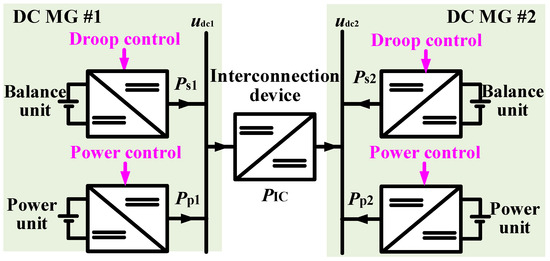
Figure 1.
Flexible-interconnection-based direct current (DC) microgrid (MG) cluster.
2.2. Operational Control Objectives
For the DC microgrid cluster based on the flexible DC interconnection shown in Figure 1, the proposed consensus-based coordinated control can achieve the following main objectives:
(1) No matter where the power disturbance occurs in the cluster, the interconnection device can automatically respond to it, adjust its transmission power flexibly, realize the linkage of all balance units in the system indirectly, provide emergency power support, and reduce the steady-state deviation of the DC voltage of the disturbed microgrid. Furthermore, the disturbance power is reasonably borne by the whole system’s balance units, making the microgrid cluster system form an organic unit.
(2) The proposed control only relies on local measurement information without communication, improves the system reliability, and has a good portability, which is convenient to introduce and transform based on the existing system.
3. Consensus-Based Coordinated Control
Aiming at the DC microgrid cluster system based on flexible interconnection (Figure 1), this paper fully considers the operating characteristics of the balance unit, power unit, and interconnection device in each DC microgrid from the overall grasp of the system. This paper then proposes a system-level consensus-based coordinated control method that includes the control of the balance unit, power unit, and interconnection device of the DC microgrid. Note that this paper aims to study the system-level control strategy of the DC microgrid cluster. For the convenience of the detailed description, each DC microgrid comprises a balance unit and a power unit. Each balance and power unit comprises a constant DC voltage source and a bidirectional buck–boost converter. The power unit in each DC microgrid adopts a constant power control strategy and simulates renewable energy or DC load fluctuations by adjusting its power reference online. The control strategies of the balance unit, power unit, and interconnection device in the DC microgrid will be described in detail.
3.1. Balance Unit Control
Figure 2 shows the topology and control strategy of the balancing unit in DC microgrid #i (i = 1, 2). The balance unit adopts the classical droop double-loop control strategy, which comprises the droop control and voltage/current control loop [20]. The balancing unit comprises a constant DC voltage source and a bidirectional buck–boost converter. Here, and represent the constant DC source voltage and inductor current, respectively; denotes the DC source side inductance; denotes the DC bus side capacitance. The balance unit control system comprises the droop and voltage/current double-loop controls. The droop control link can be expressed as follows [21]:

Figure 2.
Topology and control of the balance unit in DC microgrid #i.
In Equation (1), and represent the bus voltage setting value and the output power of the balance unit of DC microgrid #i, respectively; and represent the DC voltage output reference and droop coefficient of the droop control, respectively.
In the voltage/current control loop, the current inner-loop is used to achieve fast current tracking and the outer loop is used to achieve DC voltage stability control. Because the PI controller is stable and reliable, it is convenient for parameter tuning and is widely used in the actual microgrid system. Therefore, the voltage/current control usually adopts the PI controller. The specific expression is given by
In Equation (2), s represents a complex variable; represents the DC voltage controller; and represent the proportional and integral coefficients of the DC voltage controller , respectively; represents the output current reference of the DC voltage controller ; represents the current inner-loop controller; and represent the proportional and integral coefficients of the current inner-loop controller, respectively; represents the output duty cycle of the current inner-loop controller .
3.2. Power Unit Control Strategy
Figure 3 shows the power unit topology and its control strategy in DC microgrid #i. The balancing unit comprises a constant DC voltage source and a bidirectional buck–boost converter. Here, and represent the constant DC source voltage and inductor current, respectively; represents the DC source side inductance; represents the DC bus side capacitance. The power unit adopts the constant active power control strategy. First, the active power setting value Pseti is transformed into the inner-loop current reference value through a mathematical operation. The current fast-tracking control is then realized through the inner-loop current PI controller. The specific mathematical expression is given by
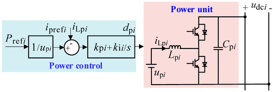
Figure 3.
Topology and control of the power unit in DC microgrid #i.
In Equation (3), represents the inner-loop current reference; represents the power setting value; represents the constant DC source voltage; represents the power controller; and represent the proportional and integral coefficients of the power controller , respectively; represents the power controller; denotes the output duty cycle.
3.3. Control of the Interconnection Device
The control of the interconnection device is the key to achieving the consensus-based coordinated control target. Based on the droop characteristics of the balance unit in the DC microgrid cluster mentioned above, this paper proposes a novel control method for the interconnection device. Figure 4 shows the specific topology and its control strategy.
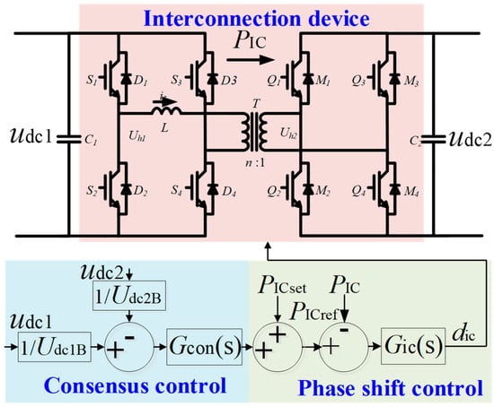
Figure 4.
Topology and control of the interlinking converter.
The interconnection device adopts an isolated bidirectional DC–DC converter, which mainly comprises two full-bridge converters, two DC capacitors, C1 and C2, an energy-storage inductor L, and a high-frequency isolation transformer T. The high-frequency isolation transformer T can effectively realize the electrical isolation and voltage matching between the interconnected subsystems. The inductance L is used for instantaneous energy storage, and n is the T ratio of the high-frequency isolation transformer, which is determined by the voltage level of the interconnected microgrid.
When the interconnection device adopts a constant prescribed power control, the control system only includes the inner-loop phase-shift control link in Figure 4. The set value of the transmission power of the interconnection device is used as the reference input of the phase-shift control and the PI controller is used to realize the constant active power control. Therefore, when a power disturbance occurs in any DC microgrid, the power output of the interconnection device is constant as the reference value , which cannot provide power support for the disturbed microgrid. To make the interconnection device flexibly adjust its power output according to the operating state of the DC microgrid, this paper introduces a consistency control loop based on the phase-shift control. The complete control strategy of the interconnection device is expressed as follows:
In Equation (4), represents the inner-loop power reference value; and represent the rated DC bus voltages of DC microgrid #1 and #2, respectively; represents the consistency controller of the interconnection device; represents the actual transmission power of the interconnection device; represents the phase-shift controller; denotes the output duty cycle of the phase-shift controller . The consensus controller and the phase-shift controller can be expressed as follows:
In Equation (5), and represent the proportional and integral coefficients of the consistency controller , respectively; and represent the proportional and integral coefficients of the phase-shift controller , respectively.
Figure 4 shows that the proposed control strategy of the interconnected device adds a consistency control loop based on the fixed active power control (phase-shift control) and uses the DC voltage of the two interconnected DC microgrids as the reference input. Therefore, the interconnected device can respond to the DC voltage fluctuation of the two interconnected DC microgrids, adjust the reference value of the interconnected power flexibly, and provide emergency power support for the disturbed power grid.
4. Theoretical Analysis
The interconnection device realizes the DC voltage coupling of the two interconnected DC microgrids through the proposed control. Therefore, the two DC grids can form an organic whole and the interconnection device can provide emergency power support for the disturbed grid to realize coordinated control of the whole system. The control effect may be different, because the response of the interconnection device may be different when different DC microgrids are disturbed. Therefore, the working principle of the proposed consensus–coordinated control strategy will be analyzed for the power disturbance of DC microgrid #1 and #2, respectively.
4.1. Scenario 1: A Power Disturbance Occurs in DC Microgrid #1
Take the output power of the DC microgrid #1 power unit increase as an example for analysis. When the interconnection device adopts a constant power control (i.e., ), the disturbance power of DC microgrid #1 will be borne by the balance unit of DC microgrid #1. According to the droop characteristics of the balance unit shown in Figure 2, the output power increment of the balance unit of DC microgrid #1 and the steady-state increment of the DC bus voltage are expressed as follows:
When the proposed control is adopted, the DC microgrid #1 bus voltage increases because the output power of the DC microgrid #1 power unit increases ΔPp1. Figure 4 shows that the DC microgrid #2 bus voltage also increases because of the PI controller of the consistency control link. As shown in Equation (4), the inner-loop power reference value of the interconnection device increases, which increases the active power of the interconnection device flowing into DC microgrid #2 and avoids the DC voltage caused by the increase in the DC microgrid #1 power.
It is assumed that the bus voltage of the two DC microgrids is stable at the rated voltage before the power disturbance occurs in DC microgrid #1. After the output power of the DC microgrid # 1 power unit increases by , due to the consistency control of the interconnection device, the steady-state deviation of the bus voltage of the two DC microgrids will satisfy:
From Figure 1 and Equations (1) and (2), the bus voltage deviation of the two DC microgrids satisfies the following relationship:
Combined with Equations (7) and (8), the bus voltage variation in the two DC microgrids and the transmission power variation in the interconnection device are given as follows:
In Equation (9), k1 and k2 represent the equivalent power distribution coefficients of DC microgrid #1 and #2, respectively. The specific forms are given by
The output power increment of the balance unit in the two DC microgrids is given as follows:
From Equations (6) and (9), when the output power of the power unit of DC microgrid #1 increases by , using the proposed consensus–coordinated control method, the interconnection device can respond to the voltage fluctuation of DC microgrid #1, flexibly adjust the output power of the interconnection device, provide emergency power support for the disturbed microgrid #1, and reduce the DC voltage deviation of DC microgrid #1. Additionally, from Equation (11), when the power disturbance occurs in DC microgrid #1, the output power variation in the interconnection device is the same as the output power variation in the balance unit in DC microgrid #2. The two DC microgrid balance units will reasonably bear the disturbance power according to their equivalent power distribution coefficient ratio (k1:k2).
4.2. Scenario 2: A Power Disturbance Occurs in DC Microgrid #2
Take the output power of the DC microgrid # 2 power unit increase as an example for analysis. When the interconnection device adopts a constant power control (i.e., ), the disturbance power of DC microgrid #2 will be borne by the balance unit of DC microgrid #2. According to the droop characteristics of the balance unit shown in Figure 2, the output power increment of the balance unit of DC microgrid #2 and the steady-state increment of the DC bus voltage are expressed as follows:
When the proposed control is adopted, the output power of the DC microgrid #2 power unit increases by ΔPp2, increasing the DC microgrid #2 bus voltage . Figure 4 shows that the DC microgrid #1 bus voltage also increases because of the consistency control link PI controller. As shown in Equation (4), the inner-loop power reference value of the interconnection device decreases, reducing the active power of the interconnection device flowing into DC microgrid #2 and avoiding the DC bus voltage caused by the increase in the DC microgrid #2 power. Due to the consistency control of the interconnection device, the steady-state deviation of the bus voltage of the two DC microgrids will satisfy Equation (7). The bus voltage variation in the two DC microgrids and the transmission power variation in the interconnection device are expressed as follows:
After the output power of the power unit of DC microgrid #2 changes, the output power increments of the balance units in the two DC microgrids become
From Equations (12) and (13), when the output power of the #2 power unit of the DC microgrid changes, using the proposed consensus–coordinated control method, the interconnection device can respond to the #2 voltage fluctuation of the DC microgrid, flexibly adjust the output power of the interconnection device, provide emergency power support for the disturbed microgrid #2, and reduce the DC voltage deviation of DC microgrid #2. Additionally, from Equation (14), when the power disturbance occurs in DC microgrid #2, the output power variation in the interconnection device is the same as that of the balance unit in DC microgrid #1. The two DC microgrid balance units will reasonably bear the disturbance power according to their equivalent power distribution coefficient ratio (k1: k2).
In summary, the equivalent power distribution coefficient of the balance unit in the two DC microgrids is different. The output power response and variation in the interconnection device may vary when different microgrids are disturbed. For example, when the power in DC microgrid #1 increases, it is hoped that it will increase the power of the interconnection device flowing out of DC microgrid #1 to avoid the DC microgrid #1 bus voltage being too high. Additionally, when the power in DC microgrid #2 increases, it is hoped that it will increase the power of the interconnection device flowing out of DC microgrid #2 to avoid the DC microgrid #2 bus voltage being too high. Therefore, the disturbance of the different microgrids may lead to differences in the power response of the interconnected devices, and the control effect of the system may vary.
5. Simulation Verification
5.1. Condition I: A Power Disturbance Occurs in DC Microgrid #1
To evaluate the effectiveness of the proposed control method, a simulation model of the DC microgrid group based on the flexible interconnection shown in Figure 1 is developed using the PSCAD/EMTDC. Table 1 and Table 2 show the main parameters of the two DC microgrids and interconnection devices. The equivalent power distribution coefficient ratio of DC microgrids #1, #2, and the two DC microgrids is 2:1, respectively.

Table 1.
Main parameters of DC microgrid #1 and #2.

Table 2.
Main parameters of the interlinking converter.
5.2. Condition I: A Power Disturbance Occurs in DC Microgrid #1
This condition is used to evaluate the effectiveness of the proposed control when the power disturbance occurs in DC microgrid #1. To simulate the load disturbance of DC microgrid #1, the power of the power unit of DC microgrid #1 is reduced from 100 to 40 kW in the eighth second. Figure 5 and Figure 6 show the simulation results of the conventional control and the proposed coordinated control methods, respectively.
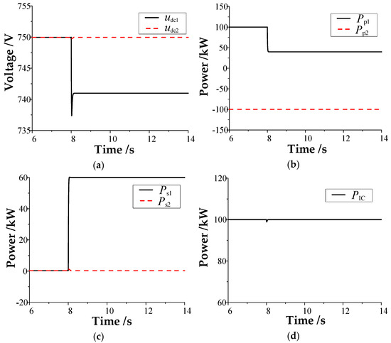
Figure 5.
Results of the traditional control method when the power disturbance occurs in DC microgrid #1: (a) DC bus voltage; (b) power unit power; (c) balancing unit power; (d) power of the interconnection device.
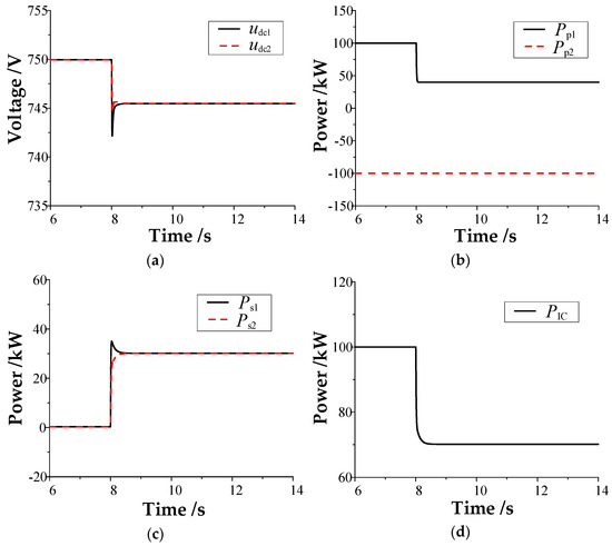
Figure 6.
Results of the proposed control method when the power disturbance occurs in DC microgrid #1: (a) DC bus voltage; (b) power unit power; (c) balancing unit power; (d) power of the interconnection device.
As shown in Figure 5, using the conventional control strategy, the transmission power of the interconnection device is maintained at its rated transmission power of 100 kW when the load disturbance occurs in DC microgrid #1. The maximum fluctuation and steady-state voltage variation in the DC bus voltage of DC microgrid #1 are approximately 13 and 9 V, respectively. DC microgrid #2 is not affected by the load disturbance of DC microgrid #2, and the DC bus voltage is still maintained at 750 V. Thus, with the conventional control strategy, after the load disturbance of DC microgrid #1 occurs, the interconnection device will not respond to it, and its DC transmission power will remain at the rated value. The load disturbance changes are all borne by the disturbed microgrid #1, resulting in a large dynamic fluctuation and steady-state deviation of its DC bus voltage.
As shown in Figure 6, when the proposed coordinated control is adopted, the transmission power of the interconnection device is reduced by approximately 30 kW after the load disturbance occurs in DC microgrid #1. The maximum variation and steady-state variation in the DC bus voltage fluctuation of DC microgrid #1 are approximately 8 and 4.5 V, respectively. Compared with the conventional control strategy, the maximum variation and steady-state variation in the DC bus voltage fluctuation of DC microgrid #1 are reduced by approximately 5 and 4.5 V, respectively. Additionally, the output power of the balance unit in the two DC microgrids increases by 30 kW because the equivalent power distribution coefficient ratio of the two DC microgrids is 1:1.
It can be seen that, when the load disturbance occurs in DC microgrid #1, the interconnection device can respond to the bus voltage of the disturbed microgrid without communication and provide emergency power support for it automatically. The two interconnected DC microgrids form an organic whole to jointly bear the load disturbance increment. Additionally, the balance unit in the two microgrids reasonably bears the load disturbance according to its equivalent power distribution coefficient ratio. The simulation results are consistent with the previous theoretical analysis.
5.3. Condition II: A Power Disturbance Occurs in DC Microgrid #2
This condition is used to evaluate the effectiveness of the proposed control when the power disturbance occurs in DC microgrid #2. To simulate the load disturbance of DC microgrid #2, the power of the power unit of DC microgrid #2 changes from −100 to −60 kW in the 8th second. Figure 7 and Figure 8 show the simulation results of the conventional control and the proposed coordinated control methods, respectively.
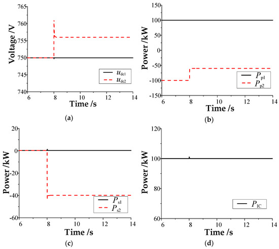
Figure 7.
Results of the traditional control when the power disturbance occurs in DC microgrid #2: (a) DC bus voltage; (b) power unit power; (c) balancing unit power; (d) power of the interconnection device.
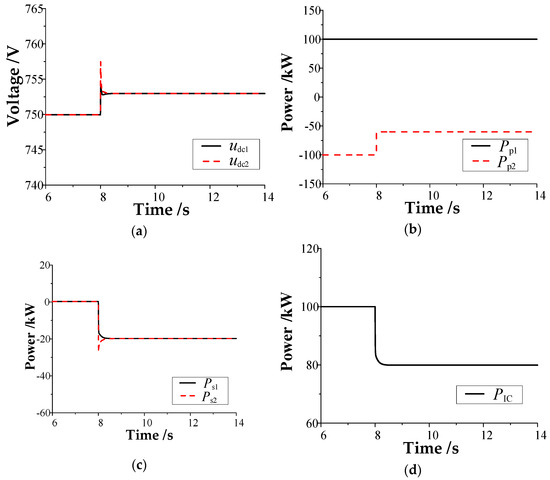
Figure 8.
Results of the proposed control when the power disturbance occurs in DC microgrid #2: (a) DC bus voltage; (b) power unit power; (c) balancing unit power; (d) power of the interconnection device.
As shown in Figure 7, using the conventional control strategy, the transmission power of the interconnection device is maintained at its rated transmission power of 100 kW when the load disturbance occurs in DC microgrid #1. The maximum fluctuation and steady-state voltage variation in the DC bus voltage of DC microgrid #2 are approximately 11 and 6 V, respectively. DC microgrid #1 is not affected by the load disturbance of the microgrid #2, and the DC bus voltage is still maintained at 750 V. It can be seen that, by using the conventional control strategy after the load disturbance occurs in DC microgrid #2, the interconnection device will not correspond to it and its DC transmission power will remain at the rated value. The load disturbance variation is borne by the disturbed microgrid #2, resulting in a large dynamic fluctuation and steady-state deviation of its DC bus voltage.
Meanwhile, when the proposed control is adopted (Figure 8), the transmission power of the interconnection device is reduced by approximately 20 kW after the load disturbance occurs in DC microgrid #2. The maximum fluctuation and steady-state variation in the DC bus voltage of DC microgrid #2 are approximately 7.5 and 3 V, respectively. Compared with the conventional control strategy, the maximum fluctuation and steady-state variation in the DC bus voltage of DC microgrid #2 are reduced by approximately 3.5 and 3 V, respectively. The output power of the balance unit in the two DC microgrids is reduced by 20 kW because the equivalent power distribution coefficient ratio of the two DC microgrids is 1:1.
It can be seen that, when the load disturbance occurs in DC microgrid #2, the interconnection device can automatically respond to the bus voltage of the disturbed microgrid without communication and provide emergency power support for it. The two interconnected DC microgrids form an organic whole to jointly bear the load disturbance increment. Additionally, the balance unit in the two microgrids reasonably bears the load disturbance according to its equivalent power distribution coefficient ratio. The simulation results are consistent with the previous theoretical analysis.
5.4. Condition III: The Equivalent Power Distribution Coefficient Ratio Is 2:1
This condition is used to evaluate the effectiveness of the proposed control strategy when the equivalent droop coefficient ratio of the two DC microgrid balancing units is 2:1. Figure 9 and Figure 10 show the simulation results of the two DC microgrids #1 and #2 after load disturbance in the 8th second, respectively. The power of the DC microgrid #1 power unit reduces from 100 to 60 kW, and the power of the DC microgrid #2 power unit changes from −100 to −60 kW.
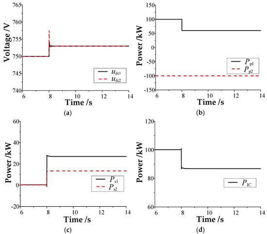
Figure 9.
Results of the equivalent power sharing ratio of 2:1 when the power disturbance occurs in DC microgrid #1: (a) DC bus voltage; (b) power unit power; (c) balancing unit power; (d) power of the interconnection device.
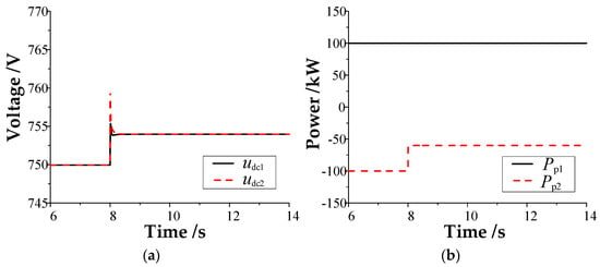
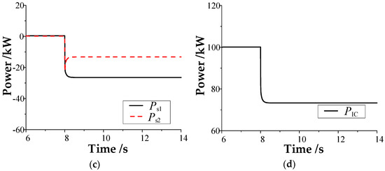
Figure 10.
Results of the equivalent power sharing ratio of 2:1 when the power disturbance occurs in DC microgrid #2: (a) DC bus voltage; (b) power unit power; (c) balancing unit power; (d) power of the interconnection device.
As shown in Figure 9 and Figure 10, no matter the load disturbance occurring in DC microgrid #1 or #2, the interconnected device can provide emergency power support for the disturbed microgrid using the proposed consensus–coordinated control strategy. Additionally, the balance unit in the two DC microgrids will reasonably bear the load disturbance according to its equivalent power distribution coefficient ratio (2:1), improve the bus voltage dynamics of the disturbed microgrid, and reduce the steady-state deviation of the bus voltage of the disturbed microgrid. The simulation results are consistent with the previous theoretical analysis.
6. Results Discussion
The simulation results indicate that, under the conventional control method, if a DC microgrid experiences a power disturbance, the interconnection device in the constant power control mode cannot respond to the disturbed microgrid. In this case, the disturbance power is entirely borne by the balance unit of the disturbed DC microgrid, making it difficult for the other microgrids to provide emergency power support. Consequently, the disturbed microgrid experiences significant DC voltage deviation.
Compared with the conventional control, the proposed control can utilize only the local measurement information without the need for mutual communication between subsystems, making the whole cluster form an organic whole. When power disturbances occur in the microgrid, all balancing units in the system can be linked to provide emergency power support for the disturbed microgrid, improve the dynamic characteristics of the disturbed microgrid’s DC voltage, and reduce the steady-state deviation of the disturbed microgrid’s DC voltage. Additionally, the disturbed power is reasonably borne by the balancing units of the whole system according to their equivalent power distribution coefficient ratios.
The comparative table of the results obtained with those already reported in the scientific literature is shown in Table 3. It can be seen from Table 3 that, compared with the existing methods, the method proposed in this paper can utilize only the local measurement information without the need of an interconnected communication system to realize the power cooperative sharing of the balance unit of the cluster system; thus, the DC voltage characteristics of the disturbed microgrid can be improved.

Table 3.
The comparative table of the results obtained with those already reported in the scientific literature.
7. Conclusions
To realize the coordinated control of the DC microgrid clusters based on flexible interconnection, conventional methods often rely on the real-time measurement of the communication system, the collection of submicrogrid information, and the transmission to the microgrid central controller, where the central controller then issues control instructions. Therefore, this method strongly depends on the communication system. Communication delay and communication failure threaten the safe and stable operation of the system and reduce the reliability of the system.
Therefore, this paper proposes a consensus–coordinated control strategy. The proposed control strategy does not require additional communication systems and only uses on-site measurement information to make the entire cluster an organic whole. The interconnection device can flexibly adjust its output power according to the bus voltage of the interconnected DC microgrid, indirectly realize the linkage of all balance units in the whole system, respond to the disturbance power, provide emergency power support for the disturbed microgrid, and improve the dynamic and steady-state characteristics of the bus voltage of the disturbed grid. The disturbance power is reasonably borne according to the equivalent power distribution coefficient ratio of each microgrid to improve the stability and reliability of the system operation. Finally, the effectiveness of the proposed control strategy is verified through the PSCAD/EMTDC simulation.
The proposed control strategy is aimed at how the whole system interacts with each part under unplanned transient shocks. In the future, it is necessary to further investigate the secondary voltage/frequency recovery control to reduce the steady-state voltage/frequency deviation.
Author Contributions
Writing—original draft, writing—review and editing, and conceptualization, D.Q.; writing—original draft, methodology, and conceptualization, C.W.; data curation and formal analysis, Y.L.; supervision, R.W.; supervision, D.H.; writing—review and editing, W.H.; validation and software, L.C. All authors have read and agreed to the published version of the manuscript.
Funding
This research was funded by the National Natural Science Foundation of China (12062014 and 52267008).
Data Availability Statement
Data are contained within the article.
Conflicts of Interest
Authors Dandan Qin and Rundong Wu were employed by the company State Grid Anhui Electric Power Company and, Chao Wang, Yuliang Liu were employed by the company State Grid Anhui Wuhu power Supply Company, Dengshan Hou was employed by the company State Grid Anhui Fuyang Power Supply Company. The remaining authors declare that the research was conducted in the absence of any commercial or financial relationships that could be construed as a potential conflict of interest.
References
- Fobes, D.M.; Nagarajan, H.; Bent, R. Optimal Microgrid Networking for Maximal Load Delivery in Phase Unbalanced Distribution Grids: A Declarative Modeling Approach. IEEE Trans. Smart Grid 2023, 14, 1682–1691. [Google Scholar] [CrossRef]
- Farrokhabadi, M.; Canizares, C.; Simpson-Porco, J.; Nasr, E.; Fan, L.; Mendoza-Araya, P.A.; Tonkoski, R.; Tamrakar, U.; Hatziargyriou, N.; Lagos, D.; et al. Microgrid Stability Definitions, Analysis, and Examples. IEEE Trans. Power Sys. 2020, 35, 13–29. [Google Scholar] [CrossRef]
- Yang, X.; Su, J.; Lü, Z.; Liu, H.; Li, R. Overview on Micro-grid Technology. Proc. CSEE 2014, 34, 57–70. [Google Scholar]
- Li, X.; Guo, L.; Wang, C.; Li, Y. Key Technologies of DC Microgrids: An Overview. Proc. CSEE 2016, 36, 1–17. [Google Scholar]
- Zhang, Q.; Zhuang, X.; Liu, Y.; Wang, C. Autonomous Current Sharing Control Strategy for Parallel Micro-sources in DC Microgrids. Power Sys. Technol. 2020, 44, 887–896. [Google Scholar]
- Liu, Z.; Yang, C.; Jiang, W.; Li, P.; Yang, B. Consensus Algorithm Based Power Distribution Technology for Energy Storage System in DC Microgrid. Autom. Electron. Power Sys. 2020, 44, 61–69. [Google Scholar]
- Li, X.; Zhang, X.; Guo, L.; Wang, C.; Zhang, S. Coordinated Control of Multiple Voltage Balancers in a Bipolar DC Microgrid. Trans. CES 2018, 33, 721–729. [Google Scholar]
- Zhi, N.; Zhang, H.; Xiao, X.; Yang, J. System-level Stability Analysis of DC Microgrid With Distributed Control Strategy. Proc. CSEE 2016, 36, 368–378. [Google Scholar]
- Shafiee, Q.; Dragičević, T.; Vasquez, J.; Guerrero, J. Hierarchical Control for Multiple DC-Microgrids Clusters. IEEE Trans. Energy Convert. 2014, 29, 922–933. [Google Scholar] [CrossRef]
- Moayedi, S.; Davoudi, A. Distributed Tertiary Control of DC Microgrid Clusters. IEEE Trans. Power Electron. 2016, 31, 1717–1733. [Google Scholar] [CrossRef]
- Leng, M.; Zhou, G.; Li, H.; Xu, G.; Blaabjerg, F.; Dragičević, T. Impedance-Based Stability Evaluation for Multibus DC Microgrid Without Constraints on Subsystems. IEEE Trans. Power Electron. 2022, 37, 932–943. [Google Scholar] [CrossRef]
- Xiong, X.; Wang, J.; Jing, T.; Yang, R.; Ye, L. Power optimization control of microgrid cluster. Electr. Power Autom. Equip. 2017, 37, 10–17. [Google Scholar]
- Zhou, L.; Zhang, C.; Jiang, J.; Li, J. Research on Bi-directional Full-bridge DC/DC Converter with Novel Control Strategy. Power Electron. 2015, 49, 7–9. [Google Scholar]
- Diao, Z.; Sun, X. An Improved Phase-shifted Control Strategy for Full-bridge DC/DC Converter. Power Electron. 2011, 45, 72–73. [Google Scholar]
- Sun, Q.; Qiu, C. Hierarchical Control of Direct Current Microgrid on Ship. Sci. Technol. Eng. 2020, 20, 10979–10988. [Google Scholar]
- Zhou, N.; Jin, M.; Wang, Q.; Su, S.; Yan, Y. Hierarchical Coordination Control Strategy for Multi-microgrid System with Series and Parallel Structure. Autom. Electron. Power Syst. 2013, 37, 13–18. [Google Scholar] [CrossRef]
- Gao, Y.; Ai, Q.; Wang, J. Consensus Cooperative Control of AC/DC Hybrid Microgrids Based on Multi-agent System. High. Volt. Technol. 2018, 44, 2372–2377. [Google Scholar]
- Yu, G.; Song, H.; Hou, R.; Gao, L.; Qu, Y. Distributed Cooperative Frequency Control for Flexible DC Interconnected Island Microgrid Cluster. Autom. Electron. Power Syst. 2020, 44, 103–111. [Google Scholar]
- Zhang, J.; Yu, A.; Huang, M. Hierarchical Coordinate Control for DC Microgrid Clusters Based on Adaptive Droop Control. Modern Power 2018, 35, 72–79. [Google Scholar]
- Lin, G.; Li, Y.; Liu, J.; Li, C. Resonance analysis and active damping strategy for shipboard DC zonal distribution network. Int. J. Electr. Power 2019, 105, 612–621. [Google Scholar] [CrossRef]
- Li, X.; Guo, L.; Li, Y.; Guo, Z.; Hong, C.; Zhang, Y.; Wang, C. A Unified Control for the DC–AC Interlinking Converters in Hybrid AC/DC Microgrids. IEEE Trans. Smart Grid 2018, 9, 6540–6553. [Google Scholar] [CrossRef]
Disclaimer/Publisher’s Note: The statements, opinions and data contained in all publications are solely those of the individual author(s) and contributor(s) and not of MDPI and/or the editor(s). MDPI and/or the editor(s) disclaim responsibility for any injury to people or property resulting from any ideas, methods, instructions or products referred to in the content. |
© 2023 by the authors. Licensee MDPI, Basel, Switzerland. This article is an open access article distributed under the terms and conditions of the Creative Commons Attribution (CC BY) license (https://creativecommons.org/licenses/by/4.0/).