Abstract
Renewable-based sources can be interconnected through power electronic converters and connected with local loads and energy storage devices to form a microgrid. Nowadays, DC microgrids are gaining more popularity due to their higher efficiency and reliability as compared to AC microgrid systems. The DC Microgrid has power electronics converters between the DC loads and renewable-based energy sources. The power converters controlled with an efficient control algorithm for maintaining stable DC bus voltage in DC microgrids under various operating modes is a challenging task for researchers. With an aim to address the above-mentioned issues, this study focuses on the DC link voltage enhancement of a DC Microgrid system consisting of PV, DFIG-based wind energy conversion system (WECS), and battery Energy Storage System (ESS). To elevate PV output voltage and minimize the oscillations in DC link voltage, a high-gain Luo converter with Cascaded Fuzzy Logic Controller (CFLC) is proposed. Droop control with virtual inertia and damping control is proposed for DFIG-based WECS to provide inertia support. Artificial Neural Network (ANN) based droop control is utilised to regulate the ESS’s State of Charge (SOC). The effectiveness of the proposed converter and its control algorithms for maintaining stable DC bus link voltage has been analysed using MATLAB/Simulink and experimentally validated using a prototype model and FPGA Spartan 6E controllers.
1. Introduction
The growing demand for electricity, the rapid depletion of fossil fuels, and the threat of global warming and climate change have necessitated the development of RES for power generation. Hydropower, wind, solar, and geothermal are examples of RES that deliver clean energy with zero carbon emissions [1,2,3]. The increased integration of renewable energy sources, distributed generations, and growing customers has resulted in the development of a concept called the Microgrid. According to CIGRE/US DoE, a Microgrid [4] is defined as a small-scale self-controllable power system that integrates several Distributed Energy Resources (DERs), loads, and energy storage systems to provide electrical power to a particular area. The Microgrid is beneficial for both electricity customers and power grid operators as it improves power quality, efficiency, and system reliability, reduces emissions, network congestion, and power losses. Microgrids are categorized into three types: AC Microgrids, DC Microgrids, and hybrid AC/DC Microgrids. Among them, the DC Microgrids are gaining popularity over traditional AC Microgrids due to various advantages, such as no consideration of reactive power regulation, synchronization in islanded mode, and harmonic or frequency conflicts. Based on operating conditions, the DC Microgrids are further classified as islanded and grid-connected modes [5,6,7].
Among the different Renewable Energy Sources (RES), photovoltaic (PV) and wind power generation systems have seen massive growth in recent years as they are more accessible and provide clean energy without any harmful emissions [8]. The electrical energy generated by PV panels is delivered to the connected load, grid, and batteries through proper power electronic interface. The output voltage of a PV panel is generally low due to varying weather conditions, which necessitates converters to enhance the voltage before connecting it to a grid-connected inverter [9]. To improve the DC-DC conversion operation and obtain a controlled output voltage, different converters such as zeta converter [10], boost converter [11], SEPIC converter [12], Cuk converter [13], buck-boost converter [14], Luo converter [15], etc., have been reported. Converters such as boost, buck-boost, and cuk generate high voltage gain when operating at high-duty cycles and cause high voltage stress across the switches. The presence of large input current ripples in cuk and SEPIC converters inhibits their MPPT performance.
For significant enhancement of converter operation in terms of percentage THD, unity power factor, settling time, overshoot, steady-state error, rise time, etc., adopting a suitable controller is crucial. The conventional PI controller is the most desirable in the PV grid-connected systems since it is simple in design, regulates DC quantities and improves system performance [16]. However, it includes a non-zero steady-state error, performance deterioration during load changes, and difficulty in determining appropriate controller values due to non-linearity and changing operating conditions [17,18]. To address these issues, Artificial Intelligence (AI) techniques such as FLC or Neural Networks (NN) are used to control the switching operation of the converter. However, NN based control approach is computationally intensive and suffers from control complexity, especially in PV applications [19,20]. In order to address the aforesaid issues in the existing literature, this research paper proposes a Cascaded Fuzzy Logic Control (CFLC) to enhance the operation of a high-gain LUO converter and to effectively enhance the DC link voltage of the DC microgrid system. The proposed cascaded control approach is capable of managing disruptions and tackling problems related to non-linearity and uncertainty.
Nowadays, DFIG-based Wind Energy Conversion Systems (WECS) are widely used for various reasons. It includes reactive power support, improved efficiency, low power loss, reduced acoustic noise, and low-rating power converters. At the same time, the growth in the number of DFIG-based wind farms results in the minimisation of system inertia, which in turn develops stability issues in Microgrids [21,22]. In the absence of Inertia, the DC Microgrids suffer from voltage stability issues, whereas the AC Microgrids suffer from frequency stability issues. The voltage fluctuations cause havoc on renewable energy sources and sensitive loads connected to the DC Microgrids. These voltage instabilities in DC bus voltage occur mainly due to sudden load variations and intermittent power generation from renewable energy sources.
In addition to inertia control, proper damping control is also essential to keep the voltage stable and ensure adequate power balance in DC Microgrids [23]. The stable and reliable operation of the DC Microgrids is further improved through droop control, which offers effective DC voltage regulation and ensures proper power-sharing [24]. A linear method based on virtual impedance has been studied in [25], where the damping control has enhanced voltage stability. However, this approach cannot provide the required recovery voltage for stabilization downstream. The DC Microgrids’ rapid and unexpected voltage variation is stabilized by providing proper inertial support [26]. A combined approach of the virtual inertia concept and damping control is adopted for the PV system [27]. However, this strategy does not apply to WECS; therefore, the contribution of inertia support from the wind turbine to the DC Microgrids for stability enhancement is not achieved. To address this issue, in this paper, an effective inertia and damping control method along with droop control is used for DFIG-based WECS to achieve effective DC link voltage enhancement in the DC Microgrid system.
Energy Storage Systems (ESSs) are other key constituents in DC Microgrids because they improve power quality, reliability, security, energy balance, and minimise energy losses. It mitigates the reverse flows caused when DER generation exceeds the load, resulting in the reduction of energy losses. When there is an excess energy generation, the ESS stores the appropriate amount of electrical energy and delivers it to the grid and load when there is a need. To attain this, ESS is connected to the DC bus through a bidirectional converter, which avoids the potential risk caused by the direct connection of ESS with the DC bus [28]. In the present work, an ANN-based droop control approach is proposed for ESS to effectively regulate the DC link voltage during normal operating conditions and during insufficient power generation from PV and WECS.
In summary, the interfacing of several DERs, ESSs, and loads to the DC bus renders the DC Microgrids a low-inertia power system with poor damping, resulting in DC link voltage fluctuations even for small disturbances. Hence, combating these current technical issues is instrumental in improving DC Microgrid’s performance. To overcome the aforesaid challenges, a new control approach has been proposed for the DC microgrid system.The main contributions of the proposed work are summarized as follows,
- A hybrid PV, wind, and ESS-based hybrid DC microgrid system is designed to meet the increasing load demand.
- A high-gain Luo converter with CFLC is proposed to enhance the PV output voltage for providing high-gain outputs, which helps for effective stabilization of the DC link voltage of the Microgrid.
- In addition, with the aid of virtual inertia and damping control approach along with droop control strategy for DFIG-based WECS, DC link voltage is effectively regulated under all operating conditions.
- An ANN-based droop control technique is proposed for ESS to adequately enhance the DC link voltage during insufficient power generation from the PV and WECS.
The simulations are done in MATLAB/ Simulink and the results are experimentally validated using the FPGA Spartan 6E controllers.
In Table 1, the current technical status of the existing literature along with its advantages and drawbacks are summarized. In addition, the merits of the proposed control approach to overcome the challenges in existing literature are listed.

Table 1.
Literature review.
The remaining part of the paper is organized as follows. Section 2 covers the literature review. A brief description of the structure and operation of the proposed DC Microgrid is covered in Section 3. Moreover, Section 3 also entails the modelling of each of the components present in the proposed Microgrid architecture. The theoretical analysis is verified through MATLAB simulation, and the derived results are discussed in detail in Section 4. In Section 5, the experimental verification is carried out using the FPGA Spartan 6E controller. The conclusion for the proposed research work with the future scope is provided in Section 6.
2. Literature Review
The growing appeal for expanded inclusion of Renewable energy sources (RES) in the structure of modern power systems is mainly influenced by factors including global warming, fossil fuel depletion, and higher fuel prices. However, the growing penetration of RES has led to the transformation of power system architecture from a generator-dominated system to an increasingly inverter-dominated system. Thus, the benefits of increased penetration of RES come at the cost of reduced system inertia, which compromises the voltage stability in DC Microgrids and frequency stability in AC Microgrids. Thus, several techniques proposed for improving system inertia are assessed in terms of their merits and demerits in Table 1.
3. Proposed Microgrid and Modelling
The schematic diagram of the proposed DC Microgrid consisting of PV, wind, and an ESS is shown in Figure 1. In this work, a Luo converter with CFLC is incorporated to boost the output voltage of the PV system and interface it with VSI. The optimized output from the CFLC is used to generate PWM pulses for controlling the switching operation of the Luo converter. In DFIG-based WECS, the controlled output is acquired by executing droop control together with virtual inertia and damping control. By feeding this combined control approach, the required pulses to control the duty cycle of the rectifier to generate a controlled DC output are obtained. Moreover, in ESS, ANN with droop control is adopted to promote its operation and to maintain its state of charge significantly. The regulated output initiates the pulse width modulator to generate pulses to control the operation of the bidirectional converter. A buck converter with a PI controller provides a controlled DC output voltage for the load. Finally, RESs and ESS are connected to the utility through VSI.
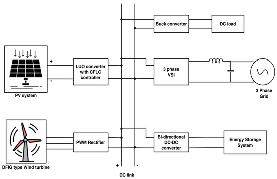
Figure 1.
Proposed microgrid system.
3.1. Luo Converter
Generally, the output voltage from a solar panel is low. To boost its voltage level and to meet varying parameter conditions, suitable converters are to be employed. In this proposed work, a Luo converter with CFLC is utilised to upgrade the conversion process and to obtain a controlled output voltage without a reversal in polarity. Implementing such a converter reduces cost and the required number of solar PV panels for power generation.
The Luo converter is a high-efficiency buck-boost DC-DC converter that provides a high output voltage with minimal current ripples. The circuit representation of the Luo converter is shown in Figure 2 with the power switch S and the freewheeling diode. The operation of the Luo converter is analyzed by two modes, which are explained in Figure 3.
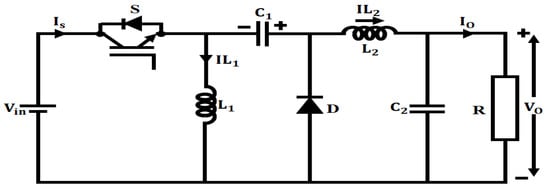
Figure 2.
Luo converter.
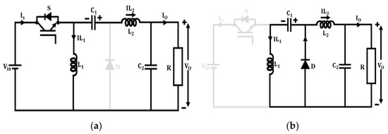
Figure 3.
Modes of operation: (a) Mode 1. (b) Mode 2.
In mode 1, the switch is in ON condition and the inductor gets charged by the supply voltage . The inductor gets charged by the capacitor and the source voltage. The diode D gets reverse-biased by the voltage of the capacitor, whereas the capacitor supplies energy to the load. The voltage across an inductor depends on the input voltage and is expressed as follows:
The voltage across an inductor is,
Here, indicates the voltage across the capacitor , denotes the voltage across the inductor , and indicates the output voltage.
In mode 2, the switch is in OFF condition, and hence the current obtained from the source becomes zero. To charge the capacitor the current flows through the freewheeling diode. The current flows through the capacitor and load and keeps itself continuous through the diode D. Now, the diode becomes forward-biased to carry the inductor current. The KVL equations for mode 2 are given below,
Applying the voltage second balance principle on the inductors and ,
where refers to duty cycle value, ton refers to the ON time period, and T refers to the total time period. Depending on the duty cycle (D) of the switch, the output voltage of the Luo-converter may be less than, equal to, or greater than the source or input voltage. When D is less than 0.5, the output voltage is less than the input voltage. When D is equal to or more than 0.5, the output voltage is larger than the input voltage. Therefore, the resulting equation for output voltage is given as,
The inductors and values have a ripple content of and are given as,
where the terms and refer to peak-to-peak ripple current of inductors.
The capacitors and values have a ripple content of and are given as
Here, the terms and specify the peak-to-peak ripple voltage of the capacitors. The operation of a high-gain Luo converter is further enhanced by applying CFLC.
3.2. Cascaded Fuzzy Logic Controller
The application of a suitable controller in the form of CFLC provides the required error compensation and improves the dynamic performance of the Luo converter. To ensure overall system control, cascaded control [31] is adopted, which can offer quick responses to disruptions. Since fuzzy sets are incredibly effective in tackling the problem of uncertainty and non-linearity in a system, fuzzy cascade control structures are developed and utilised in this present work.
Figure 4 shows the structure of the proposed cascaded control technique consisting of two FLCs connected in a series. The reference control signal from the first FLC drives the second FLC to generate the necessary duty cycle command that controls the switching pulses of the converter. The second FLC is designed to minimise distortions, which have a detrimental effect on the output of the Luo converter.
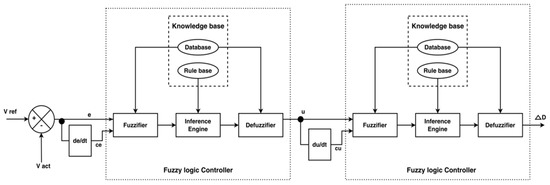
Figure 4.
Structure of CFLC.
The voltage output of the converter is compared to the reference voltage and an error is obtained. The error in addition to the change in error , is fed as input to the CFLC. The CFLC optimised output is then given to the pulse width modulator to provide the required pulses for enhancing the converter output efficiently. The CFLC technique used in this paper is a closed-loop control methodology applied to maintain a constant output voltage of the PV system.
Figure 5a,b illustrates the triangular membership functions of inputs and in addition to the CFLC rule base. The rule base is usually represented by fuzzy linguistic variables. For the designed rule base, the linguistic control rule is given as,
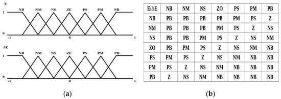
Figure 5.
(a) Triangular membership functions. (b) CFLC rule base.
Here, the numeric value of the control is specified as , change of error is specified as , the output is specified as , the error is specified as , and the kth rule is specified as . The linguistic value of change of error and error is specified as , respectively.
3.3. Virtual Inertia and Damping Control
The term inertia is a system parameter that refers to the ability of the Microgrid to store and infuse kinetic energy into the electric power system. Inertia is considered to be quite an essential property required to control and maintain the smooth functioning of the entire electric power system. Insufficient inertia results in frequency instability in the AC Microgrid and voltage instability in DC Microgrids. The voltage instability causes deteriorating effects on the renewable power sources and sensitive loads interfaced with the DC Microgrid. The fluctuations in DC bus voltage result from massive distortions caused by step changes, an arbitrary connection of loads, and the variable, uneven power introduced by renewable power sources. The damping effect is considered essential to DC Microgrid owing to its inherent nature to subdue voltage fluctuations. Hence, for the stable operation of the Microgrid, the inertia effect, in addition to damping capability, is critical. An ideal inertia and damping control technique for WECS is adopted in this research to enhance the DC Microgrid’s voltage stability and power balance, as illustrated in Figure 6.
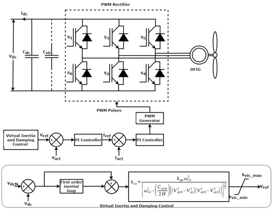
Figure 6.
WECS with droop control and virtual inertia and damping control.
The dc-link active power balance equation is represented in (23)
where is the active power output of the PWM rectifier, is the active power injected into the DC Microgrid, is the dc capacitor voltage, and is the dc bus voltage. During the steady-state operating condition, since constant DC voltage is maintained. During unbalanced operating conditions or uncertainties, the variation in may occur, leading to either the charging or discharging of the DC capacitor. It results in the reduction of the dc voltage change rate. The wind turbine is a controllable power source and can reduce this dc voltage change rate. It provides additional power through the application of inertia and damping control [32]. The inertial power supplied () by the WECS to maintain the dc-link power balance is represented by the following Equation (24),
The value of inertial power is determined as
By adjusting the value of the PWM rectifier’s virtual inertial control coefficient , the DC Microgrid inertia is regulated as per the following equation,
The effect of inertia power on the DC Microgrid can be described as a virtual capacitor connected in parallel with a capacitor . The capacity demands of actual capacitor can be reduced by increasing the magnitude of , which benefits the DC Microgrid’s working ability. The variable speed of the wind turbine results in an alteration of output electric power according to the motion equation of the rotor.
where the terms and refer to the electromagnetic and mechanical power of the DFIG, respectively. The rotor speed is represented by and the inertial time constant is represented by. When the DC Microgrid experiences voltage fluctuations, the kinetic energy stored in the rotor provides the required virtual inertial power .
where refers to the virtual inertial control coefficient of WECS. The dc bus voltage is related to the wind speed through the following equation,
where the optimum power coefficient of the wind turbine is represented by . The terms and refer to the dc bus voltage of the earlier sample and the dc bus voltage in the vicinity of the rated value. The virtual inertial coefficient is given as,
3.4. PI Controller Based Droop Control
The main objective of applying the PI controller-based droop control technique [33] is to ensure the optimal power deliverance of WECS according to its capacity. Both the voltage control and current control loop of the droop control use a PI controller for error compensation. The PI controller of the voltage control loop compares the actual DC output voltage of the PWM rectifier with the reference voltage and generates a reference current . The reference current generated from the PI controller of the current control loop is compared with the actual current obtained from the PWM rectifier to produce a control signal. The resultant control signal controls the switching operation of the PWM rectifier to deliver a controlled DC output, as shown in Figure 6.
3.5. Modelling of the ESS with ANN Based Droop Control
3.5.1. Description of ANN
The ANN replicates the working of the human brain to find the solution to complex problems. In this work, the feed-forward neural network (FFNN) is selected. The FFNN comprises of an input layer, an output layer, and a hidden layer. Its performance relies on the training process, the number of neurons in the hidden layer, and the activation function used by the hidden layer. The total number of neurons in the hidden layers is 50. The tan sigmoid activation function is used for the hidden layer, while the linear activation function is used for the output layer. The number of training epochs is 1000, and the Levenberg-Marquardt algorithm is used as the learning algorithm. The learning rate is 0.01. The training time of ANN is approximately 20 min, and the attained accuracy is about 92%. The input signal passes through the network layers, and the corresponding weights are adjusted during training. Similar the PI controller, the ANN controller is also provided with an error signal and an integral of the error signal as input.
where, , and specify the reference signal, actual signal, and error signal, respectively. Finally, the output of the ANN controller is used to tune the parameters of the PI controller.
Utilising ANN for ESS control has a number of benefits, one of which is their capacity to learn and adjust to changing circumstances. The ANN is capable of modifying its settings as system data is gathered to optimise performance based on the system’s current state and provide more precise and accurate control. Thus, ANN is a potential technique for controlling ESS in a variety of applications since it offers a flexible and effective approach to ESS control.
3.5.2. Structure of Bidirectional Converter with ANN Optimized Droop Control
A bidirectional power converter is used to interface the ESS to the dc link since it effectively assists the process of charging and discharging. The surplus power generated from both renewable sources is stored in the ESS. In a short supply of power, the stored energy from the ESS acts as the secondary backup power source. To overcome the voltage imbalance issues of the DC Microgrid due to ESS over-discharge/charge conditions, an ANN-optimised droop control technique [34] is introduced, as shown in Figure 7.
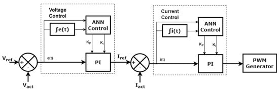
Figure 7.
ANN optimized droop control technique.
The reference voltage of the ESS maintained at the input is. The output of the voltage control loop is the desired reference current value . The output of the current control loop enables the PWM generator to initiate pulses that control the switching operation of the bidirectional converter, as seen in Figure 8.
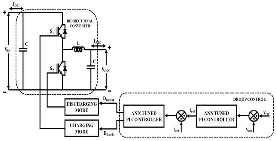
Figure 8.
Structure of bidirectional converter with droop control.
The droop control technique also controls the SOC condition of the ESS. The battery gets charged at a state of 20% SOC value and gets discharged at a state of 80% SOC value. The battery SOC, which refers to the charge contained in the battery in relation to its volume, is expressed as,
where the battery capacity, in addition to the battery charging current, is specified as Q and , respectively. When operated in buck mode, the bidirectional converter has the ESS in the place of load and the DC link as the source, and thus, the charging of the battery takes place. In the boost mode of the operation of the converter, battery discharges and ESS serve as a source in this mode. The capacitor and inductor value during boost mode and buck mode of the operation is given as,
where the ripple voltage and ripple current are specified as and , respectively. The terms refers to output resistance, switching frequency, and duty ratio.
4. Results and Discussion
4.1. Simulation Results and Analysis
4.1.1. PV System
The solar panel simulation model is based on the PV module manufactured by TATA Solar Power. The parameter specifications of solar panels and Luo converter are listed in Table 2 and Table 3.
Table 2.
Specification of solar panel parameters.
Table 3.
Specification of high-gain converter parameters.
In the present study, a constant temperature of and the solar intensity value of about is applied as input to the solar panel, as seen in Figure 9a,b. The solar intensity is 800 till 0.2s, and then it increases to at the time of.
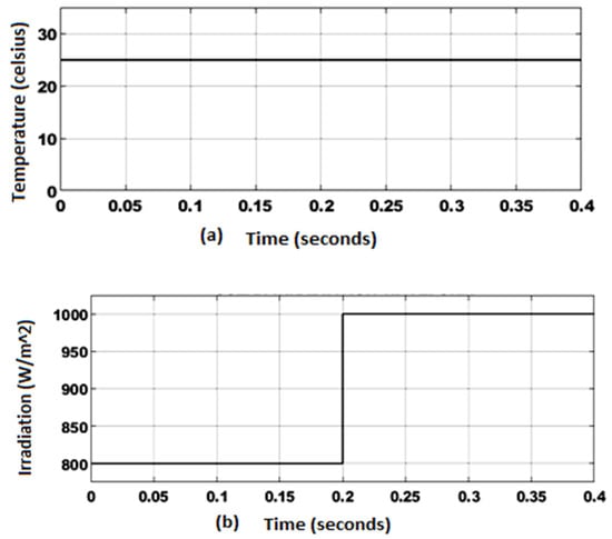
Figure 9.
(a) PV panel temperature and (b) irradiation.
Figure 10 shows the PV panel output voltage and current waveforms. Initially, the output voltage from the PV panel shows a voltage of, and due to the variation in irradiation level after a voltage of is obtained. Considering the PV panel output current, it exhibits variations due to intensity and irradiation after while maintaining an output current of .
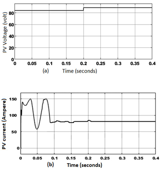
Figure 10.
(a) PV output voltage and (b) output current.
The waveforms representing the output voltage and current of the Luo converter are shown in Figure 11a,b. Initially, minor fluctuations occur in the output voltage, and after, a stable voltage of is attained. The CFLC approach used for the control of the converter aids in maintaining a constant voltage. Similarly, the output current shows a steady increase, and after a stable value of about is obtained by employing a high-gain converter with CFLC.
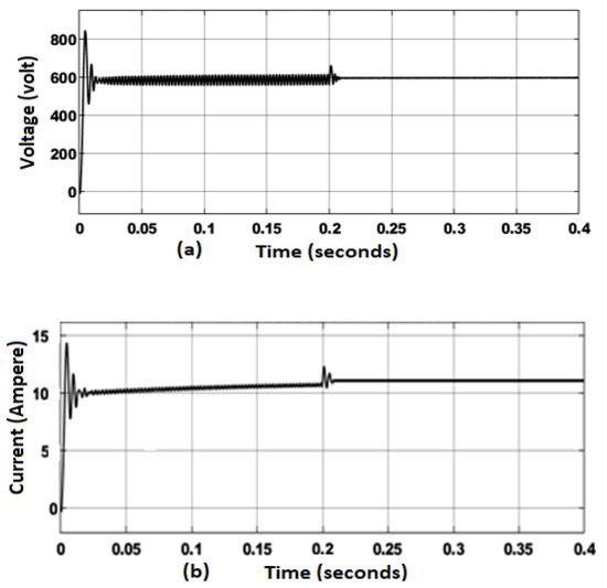
Figure 11.
(a) Converter output voltage and (b) converter output current.
- Discussion:
Table 4 compares the efficiency of the Luo converter with other converters. It validates that the efficiency of the Luo converter with CFLC is better than the other converters as it delivers an efficiency of 92%.
Table 4.
Comparison of the efficiency of converters.
Additionally, the percentage THD of different VSI-fed converters is calculated and compared with the Luo converter, as shown in Figure 12a. The percentage THD value obtained by the Luo converter is about, which is eminently lower than the other converters.
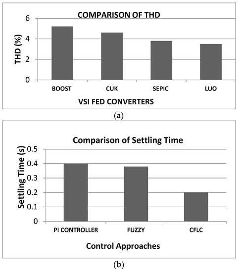
Figure 12.
(a) Percentage THD comparison and (b) controller settling time.
Similarly, to show the performance of CFLC, a comparison of the settling time is made with the conventional controllers, and their results are depicted in Figure 12b. It indicates that the CFLC approach exhibits an improved settling time of , whereas the Fuzzy and PI controller shows a settling time of [38] and [39], respectively.
4.1.2. DFIG-Based WECS
The parameter specifications of WECS, Buck converter, and Load are listed in Table 5.
Table 5.
Specification of parameters.
The waveforms representing the output voltage of the DFIG-based WECS and the PWM rectifier are shown in Figure 13a,b. At the initial stage, the rectifier output voltage exhibits minor fluctuations, and after, a constant voltage of is obtained by applying droop control and virtual inertia and damping control.
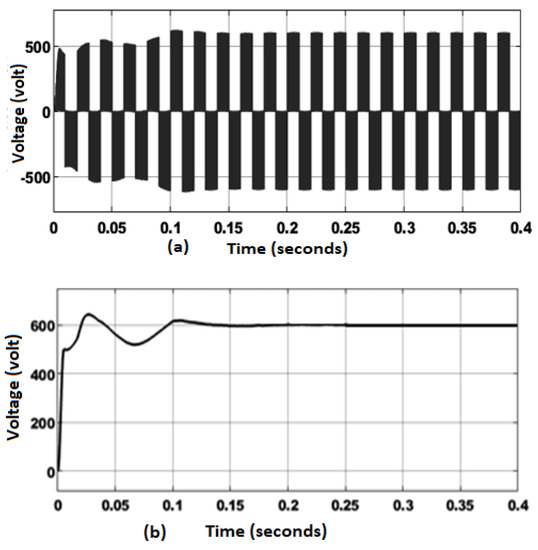
Figure 13.
(a) DFIG-based WECS output voltage and (b) PWM rectifier output voltage.
- Discussion:
Figure 14a indicates the DC link voltage waveform of droop control without inertia and damping control. The obtained voltage shows regular fluctuations due to the absence of a control approach and hence, settles only at. From Figure 14b, which represents the DC link voltage waveform of droop control with inertia and damping control, it is noted that a constant stable voltage of is maintained in the DC link from onwards.
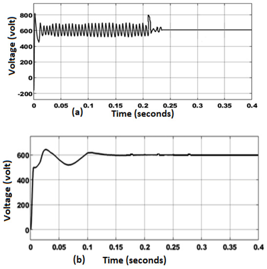
Figure 14.
DC link voltage: (a) droop control without inertia and damping control and (b) droop control with inertia and damping control.
Figure 14b shows that with the injection of various loads (by applying and analysing under different reference power values) at, , and , the DC link voltage remains stable due to the application of virtual inertia and damping control. In contrast, the fluctuations are more in the case of a system without virtual inertia and damping control. Table 6 represents step response parameters related to droop control with virtual inertia and damping control and without virtual inertia and damping control.
Table 6.
Step response parameters comparison.
4.1.3. Energy Storage System
The parameter specification of ESS comprises of eight batteries and a capacitance. The battery gets charged at a state of 20% SOC value and gets discharged at a state of 80% SOC.
Figure 15a,b shows the waveforms representing the output voltage of the ESS under PI-based control and ANN-based control.
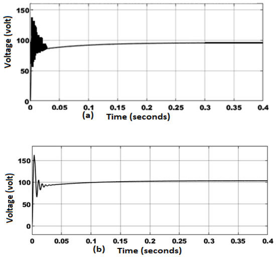
Figure 15.
ESS output voltage waveform: (a) With PI controller and (b) with ANN controller.
It depicts that a voltage of is maintained at ESS due to the PI controller and a voltage of is maintained at ESS due to the application of the ANN controller.
- Discussion:
The improvements of ANN over the conventional PI controller are, with the PI-based control the voltage maintained at the ESS is comparatively low and is around whereas with ANN-based control, the voltage maintained at the ESS is around. Moreover, the output voltage of the ESS becomes stable at with the assistance of ANN-based droop control, whereas the output voltage of the ESS becomes stable only at with the assistance of PI-based control, as shown in Figure 15a,b.
4.1.4. Grid Synchronization
When the DC link voltage is fed to the inverter, it performs DC to AC conversion. By applying DQ theory-based control forVSI, current harmonics are minimised effectively.
The waveforms representing grid voltage and current at a reference power of are illustrated in Figure 16. The grid voltage obtained is which is maintained constant without any fluctuations. Corresponding to constant output voltage, the grid output current is stable and is given by A.
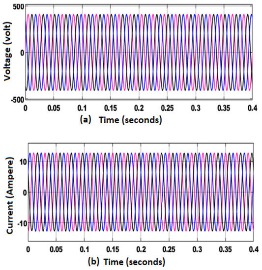
Figure 16.
Waveforms of grid at reference power of: (a) Voltage and (b) Current.
The waveforms that present the magnitude of real and reactive power of grid at a reference power of are shown in Figure 17. The real power has a high value of and the magnitude of reactive power is about.
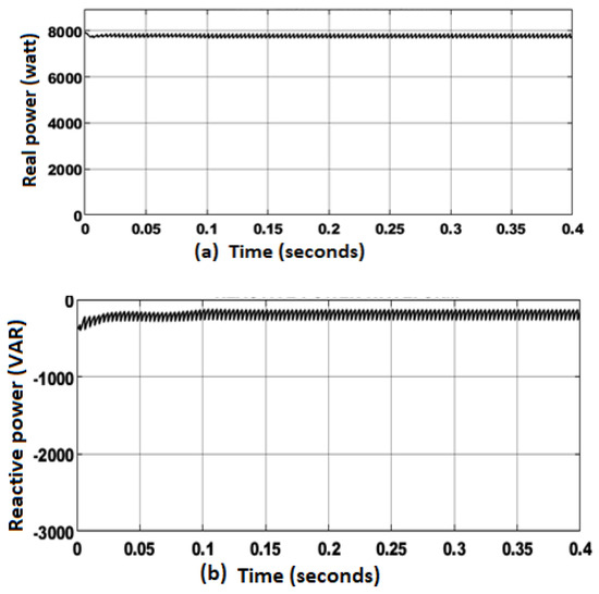
Figure 17.
Grid at reference power of (a) Real power and (b) Reactive power.
The waveforms denoting grid voltage current at a reference power of are illustrated in Figure 18a,b. The grid output voltage obtained is given by which is maintained constant without any fluctuations. Corresponding to the constant output voltage, the grid output current is stable and is given by.
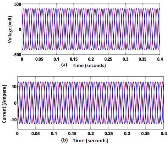
Figure 18.
Waveforms of grid at reference power of (a) Voltage and (b) Current.
The waveforms representing the magnitude of real and reactive power of grid at the reference power of are shown in Figure 19a,b.
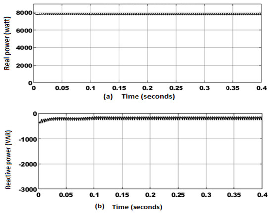
Figure 19.
Grid at reference power of (a) Real power and (b) Reactive power.
The real power has a high value of and the magnitude of reactive power is comparatively less, at about. This reduced reactive power causes a more negligible effect on voltage levels which maintains voltage stability and guarantees effective grid synchronization. Figure 20 shows the obtained percentage THD value that validates the proposed methodology’s contribution in the THD minimisation process. An enhanced THD value of is attained with the proposed system, indicating reduced harmonics.
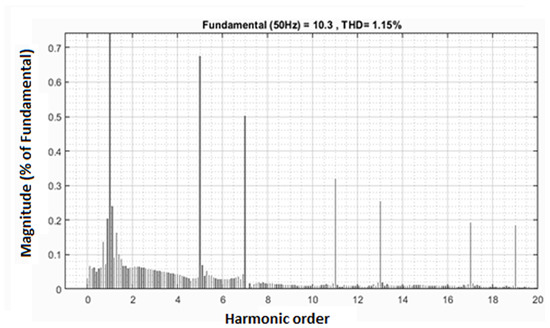
Figure 20.
THD waveform for Simulation analysis.
5. Hardware Analysis
The significant properties of the developed power conversion system are analysed by a laboratory-scaled prototype of the PV-wind-ESS system in the FPGA Spartan 6E controller. Figure 21 indicates the hardware setup of the proposed approach with PV simulator, ESS, and DFIG. The function of a wind turbine simulator is accomplished using a 1 KW motor generator, while a real-time digital simulator is used for modelling wind speed and wind turbines. Moreover, an isolated driver system and inbuilt PWM generators are used to govern the converters’ switches. The setup comprises of input-output pins used for the power converter operation through electromechanical relays. The FPGA Spartan 6E controller is used for designing and programming the overall control system. An analog-to-digital converter (ADC) is integrated with an FPGA controller for the conversion of analog signals to digital form to be processed by the controller.
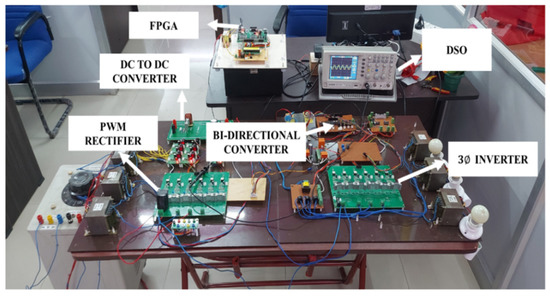
Figure 21.
Hardware setup.
5.1. FPGA Implementation Flowchart
The flowchart for the FPGA implementation is given in Figure 22.
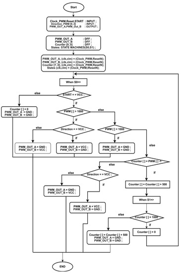
Figure 22.
Flowchart of FPGA implementation.
The hardware components and their specifications with the manufacturer’s details are provided in Table 7.
Table 7.
Hardware components and their specifications with manufacturer’s details.
The role of each hardware component is summarised as follows:
- A PV (Photovoltaic) Simulator is an electronic device that emulates the behaviour of actual PV panels in a controlled laboratory environment.
- The role of a DFIG module is to convert variable AC power from a wind turbine into stable DC power that can be used by a DC microgrid.
- A wind turbine with a power rating of 1 kW is utilised as an electrical power source in a hardware setup aimed at showcasing the potential of wind energy.
- The ESS 48 V LiFePO4 battery serves as an energy storage solution for a DC microgrid setup. It provides a reliable source of backup power, peak shaving, load shifting, and load balancing, and contributes to the overall sustainability of the microgrid system.
- A 1 kW DC-DC converter, featuring an input voltage range of 85 V and an output voltage range of 600 V, regulates the voltage level, converts power, isolates different parts of the system, and improves the power quality of the overall system.
- The TLP250 driver system plays a crucial role in controlling and managing the power flow between different components of the system.
- A bidirectional 1 kW, 100 Ah DC-DC converter, featuring an input voltage range of 400 V and an output voltage range of 48 V, is designed to convert electrical power from one voltage level to another in both directions.
- A three-phase inverter with a rating of 600 V and 100 A facilitates the conversion of DC power to AC power, enables bi-directional power flow, and provides voltage and frequency regulation to ensure smooth and efficient operation of the microgrid.
- The FPGA Spartan 6 development board can serve as a versatile and flexible hardware platform for implementing control, communication, and management functions in a DC microgrid system.
5.2. Experimental Results
5.2.1. PV System
The PV system’s output voltage and current fluctuate constantly due to the direct impact of changes in solar irradiation and ambient temperature. Figure 23a,b represents the voltage and current waveforms of the PV system that demonstrate the unstable nature of its output. In the initial stage, an output voltage of 48 V is attained with some fluctuations, and then it slightly increases due to the irradiance effect and remains at a stable voltage of 50 V. Subsequently, 11 A of peak spike in current occurs initially and with a slow decline a current of 3 A is reached and remains stable at the PV output. This lower PV output is given as input to the converter and is enhanced in a wider range without any disturbance.
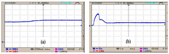
Figure 23.
(a) Voltage waveform of PV and (b) current waveform of PV.
The converter receives a low PV output voltage of 50 V and maximises the voltage to an extensive range of 600 V without any disruptions, as shown in Figure 24a. In Figure 24b, it is observed that some initial fluctuations occur in the current waveform for a certain period, and then it attains a constant current value of 5 A due to the application of cascaded fuzzy logic control. It validates that the significance of this converter with CFLC provides higher voltage gain and helps in improving the DC link voltage.
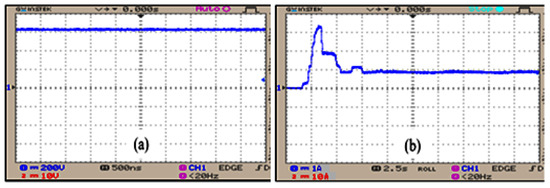
Figure 24.
(a) Voltage waveform of converter and (b) current waveform of converter.
5.2.2. DFIG-Based WECS
DFIG voltage swings in general, but with the aid of droop control and virtual inertia and damping control, a consistent DC link voltage of 600 V is produced, and it is maintained in the DC link. The waveforms representing DFIG and PWM rectifier output voltage are depicted in Figure 25a,b. It illustrates that the DFIG delivers an output voltage of 575 V, and it is attained with certain oscillations in Figure 25a. Hence, the PWM rectifier is employed to provide an optimal output of 600 V by constantly maintaining the DFIG output without any disruptions, and its waveform is given in Figure 25b.
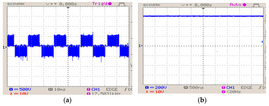
Figure 25.
Output voltages: (a) DFIG and (b) PWM rectifier.
Figure 26 analyses the DC link voltage, and it illustrates that initial fluctuations in the DC link voltage occur and remain constant at 600 V after a certain period. It validates that the implication of the introduced approaches and control measures in retaining the DC link voltage is extensively high.
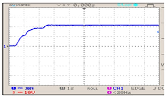
Figure 26.
DCl Link voltage.
5.2.3. Energy Storage System
The alternative backup power approach employs an ESS to overcome the imbalance in power and to achieve a continuous supply. With the assistance of ANN droop control, the DC link voltage is effectively maintained by the ESS at 600 V without any disruptions, and it is specified through the waveform shown in Figure 27.
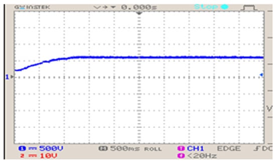
Figure 27.
ESS voltage.
5.2.4. Grid Synchronisation
The optimal output of VSI is attained through the implementation of the proposed methodologies. Hence, an enhanced VSI output is attained, and it compensates for the grid voltage and current in an efficient manner, and their waveforms are portrayed in Figure 28. It is observed from the waveform that both the current and voltage are retained as constant without any disruptions. As THD minimisation is one of the primary objectives of this present study, it is appreciably minimised with the aid of this proposed approach. Figure 29 highlights the THD waveform, and it is prominent that the obtained THD of is comparatively lower than the others.
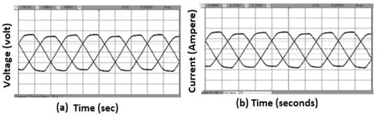
Figure 28.
(a) Grid voltage and (b) grid current.
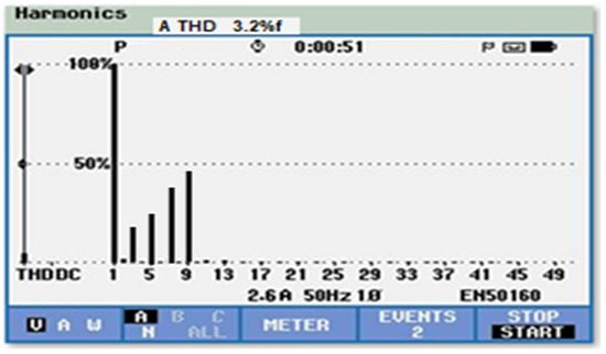
Figure 29.
THD waveform for Experimental analysis.
6. Conclusions
This paper proposes a new control strategy for converters achieving regulated DC Link voltage of the grid-connected DC microgrids. The dynamic performance of the proposed controller is investigated at various operating conditions.The main outcomes of the proposed work are summarized as: (1) Significant enhancement of output voltage of the PV system by the proposed high-gain converter with CFLC and delivering an improved system efficiency of 92%. (2) DFIG-based WECS with the proposed droop control along with ANN-based ESS control helps to retain the constant output current and DC link voltage of 600 V. With the adoption of virtual inertia and damping control, faster system balance is ensured with a reduced settling time of to reach the steady state operation of a microgrid during load changes. (3) The reduction in the value of percentage THD to 1.15% further justifies the effectiveness of the adopted control approach. The efficiency of the proposed converters and their control algorithms for retaining constant DC bus voltage has been analysed at various operating conditions using MATLAB/Simulink and the same has been experimentally validated. As a future scope, it is possible to achieve better DC link voltage improvement for DC microgrids through the implementation of improved converter topologies, optimized controllers, and powerful algorithms. AI and meta-heuristic optimisation approaches can be used for converter control to attain a robust response for a nonlinear system that is subject to uncertainty, sudden load disturbance, and variation in microgrid network parameters. Such approaches yield lesser complexity to design the controller without prior knowledge of the system parameters.
Author Contributions
Methodology, S.R.; Software, S.R.; Formal analysis, S.R.; Investigation, S.R.; Writing—original draft, S.R.; Writing—review & editing, V.T., N.K. and N.P.; Supervision, V.T.; Project administration, V.T. All authors have read and agreed to the published version of the manuscript.
Funding
This research received no external funding.
Data Availability Statement
No new data were created or analysed in this study. Data sharing is not applicable to this article.
Conflicts of Interest
The authors declare no conflict of interest.
References
- Qazi, A.; Hussain, F.; Rahim, N.A.; Hardaker, G.; Alghazzawi, D.; Shaban, K.; Haruna, K. Towards Sustainable Energy: A Systematic Review of Renewable Energy Sources, Technologies, and Public Opinions. IEEE Access 2019, 7, 63837–63851. [Google Scholar] [CrossRef]
- Son, Y.; Mukherjee, S.; Mallik, R.; Majmunovi’c, B.; Dutta, S.; Johnson, B.; Maksimović, D.; Seo, G.S. Levelized Cost of Energy-Oriented Modular String Inverter Design Optimization for PV Generation System using Geometric Programming. IEEE Access 2022, 10, 27561–27578. [Google Scholar] [CrossRef]
- Chaudhuri, A.; Datta, R.; Kumar, M.P.; Davim, J.P.; Pramanik, S. Energy Conversion Strategies for Wind Energy System: Electrical, Mechanical and Material Aspects. Materials 2022, 15, 1232. [Google Scholar] [CrossRef] [PubMed]
- Meng, L.; Shafiee, Q.; Trecate, G.F.; Karimi, H.; Fulwani, D.; Lu, X.; Guerrero, J.M. Review on control of DC microgrids and multiple microgrid clusters. IEEE J. Emerg. Sel. Top. Power Electron. 2017, 5, 928–948. [Google Scholar] [CrossRef]
- Kumar, D.; Zare, F.; Ghosh, A. DC Microgrid Technology: System Architectures, AC Grid Interfaces, Grounding Schemes, Power Quality, Communication Networks, Applications, and Standardisations Aspects. IEEE Access 2017, 5, 12230–12256. [Google Scholar] [CrossRef]
- Al-Ismail, F.S. DC Microgrid Planning, Operation, and Control: A Comprehensive Review. IEEE Access 2021, 9, 36154–36172. [Google Scholar] [CrossRef]
- Ahmed, M.; Meegahapola, L.; Vahidnia, A.; Datta, M. Stability and Control Aspects of Microgrid Architectures–A Comprehensive Review. IEEE Access 2020, 8, 144730–144766. [Google Scholar] [CrossRef]
- Tang, Z.; Yang, Y.; Blaabjerg, F. Power Electronics: The Enabling Technology for Renewable Energy Integration. CSEE J. Power Energy Syst. 2022, 8, 39–52. [Google Scholar] [CrossRef]
- Karafil, A.; Ozbay, H.; Oncu, S. Design and Analysis of Single-Phase Grid-Tied Inverter with PDM MPPT-Controlled Converter. IEEE Trans. Power Electron. 2020, 35, 4756–4766. [Google Scholar] [CrossRef]
- Kumar, R.; Singh, B. BLDC Motor-Driven Solar PV Array-Fed Water Pumping System Employing Zeta Converter. IEEE Trans. Ind. Appl. 2016, 52, 2315–2322. [Google Scholar] [CrossRef]
- Bao, D.; Kumar, A.; Pan, X.; Xiong, X.; Beig, A.R.; Singh, S.K. Switched Inductor Double Switch High Gain DC-DC Converter for Renewable Applications. IEEE Access 2021, 9, 14259–14270. [Google Scholar] [CrossRef]
- Tey, K.S.; Mekhilef, S.; Seyedmahmoudian, M.; Horan, B.; Oo, A.T.; Stojcevski, A. Improved Differential Evolution-Based MPPT Algorithm using SEPIC for PV Systems under Partial Shading Conditions and Load Variation. IEEE Trans. Ind. Inform. 2018, 14, 4322–4333. [Google Scholar] [CrossRef]
- de Morais, J.C.D.S.; de Morais, J.L.D.S.; Gules, R. Photovoltaic AC Module based on a Cuk Converter with a Switched-Inductor Structure. IEEE Trans. Ind. Electron. 2019, 66, 3881–3890. [Google Scholar] [CrossRef]
- Rana, N.; Banerjee, S. Development of an Improved Input-Parallel Output-Series Buck-Boost Converter and Its Closed-Loop Control. IEEE Trans. Ind. Electron. 2020, 67, 6428–6438. [Google Scholar] [CrossRef]
- Singh, B.; Kushwaha, R. Power Factor Preregulation in Interleaved Luo Converter-Fed Electric Vehicle Battery Charger. IEEE Trans. Ind. Appl. 2021, 57, 2870–2882. [Google Scholar] [CrossRef]
- Alturki, F.A.; Omotoso, H.O.; Al-Shamma’a, A.A.; Farh, H.M.; Alsharabi, K. Novel Manta Rays Foraging Optimization Algorithm based Optimal Control for Grid-Connected PV Energy System. IEEE Access 2020, 8, 187276–187290. [Google Scholar] [CrossRef]
- Ali, M.; Tariq, M.; Lodi, K.A.; Chakrabortty, R.K.; Ryan, M.J.; Alamri, B.; Bharatiraja, C. Robust ANN-based Control of Modified PUC-5 Inverter for Solar PV Applications. IEEE Trans. Ind. Appl. 2021, 57, 3863–3876. [Google Scholar] [CrossRef]
- Yap, K.Y.; Beh, C.M.; Sarimuthu, C.R. Fuzzy Logic Controller-based Synchronverter in Grid-Connected Solar Power System with Adaptive Damping Factor. Chin. J. Electr. Eng. 2021, 7, 37–49. [Google Scholar] [CrossRef]
- Singh, R.; Bansal, R.C. Optimisation of an Autonomous Hybrid Renewable Energy System using Reformed Electric System Cascade Analysis. IEEE Trans. Ind. Inform. 2019, 15, 399–409. [Google Scholar] [CrossRef]
- Muralikumar, K.; and Ponnambalam, P. Comparison of Fuzzy and ANFIS Controllers for Asymmetrical 31-Level Cascaded Inverter with Super Imposed Carrier PWM Technique. IEEE Access 2021, 9, 82630–82646. [Google Scholar] [CrossRef]
- Hu, J.; Huang, Y.; Wang, D.; Yuan, H.; Yuan, X. Modeling of Grid-Connected DFIG-Based Wind Turbines for DC-Link Voltage Stability Analysis. IEEE Trans. Sustain. Energy 2015, 6, 1325–1336. [Google Scholar] [CrossRef]
- Tan, J.D.; Chang, C.C.W.; Bhuiyan, M.A.S.; Nisa’Minhad, K.; Ali, K. Advancements of Wind Energy Conversion Systems for Low-wind Urban Environments: A review. Energy Rep. 2022, 8, 3406–3414. [Google Scholar] [CrossRef]
- Zhu, X.; Meng, F.; Xie, Z.; Yue, Y. An Inertia and Damping Control Method of DC-DC Converter in DC Microgrids. IEEE Trans. Energy Convers. 2019, 35, 799–807. [Google Scholar] [CrossRef]
- Li, G.; Du, Z.; Shen, C.; Yuan, Z.; Wu, G. Coordinated Design of Droop Control in MTDC Grid Based on Model Predictive Control. IEEE Trans. Power Syst. 2017, 33, 2816–2828. [Google Scholar] [CrossRef]
- Lu, X.; Sun, K.; Guerrero, J.M.; Vasquez, J.C.; Huang, L.; Wang, J. Stability Enhancement based on Virtual Impedance for DC Microgrids with Constant Power Loads. IEEE Trans. Smart Grid 2015, 6, 2770–2783. [Google Scholar] [CrossRef]
- Wu, W.; Chen, Y.; Luo, A.; Zhou, L.; Zhou, X.; Yang, L.; Dong, Y.; and Guerrero, J.M. A Virtual Inertia Control Strategy for DC Microgrids Analogized with Virtual Synchronous Machines. IEEE Trans. Ind. Electron. 2016, 64, 6005–6016. [Google Scholar] [CrossRef]
- Peng, Q.; Yang, Y.; Liu, T.; Blaabjerg, F. Coordination of Virtual Inertia Control and Frequency Damping in PV Systems for Optimal Frequency Support. CPSS Trans. Power Electron. Appl. 2020, 5, 305–316. [Google Scholar] [CrossRef]
- Li, X.; Wang, S. Energy Management and Operational Control Methods for Grid Battery Energy Storage Systems. CSEE J. Power Energy Syst. 2021, 7, 1026–1040. [Google Scholar] [CrossRef]
- Unamuno, E.; Barrena, J.A. Design and Small-Signal Stability Analysis of a Virtual-Capacitor Control for DC Microgrids. In Proceedings of the 2017 19th European Conference on Power Electronics and Applications (EPE’17 ECCE Europe), Warsaw, Poland, 11–14 September 2017; p. 1. [Google Scholar] [CrossRef]
- Jin, Z.; Meng, L.; Han, R.; Guerrero, J.M.; Vasquez, J.C. Admittance-Type RC-Mode Droop Control to Introduce Virtual Inertia in Dc Microgrids. In Proceedings of the 2017 IEEE Energy Conversion Congress and Exposition (ECCE), Cincinnati, OH, USA, 1–5 October 2017; pp. 4107–4112. [Google Scholar] [CrossRef]
- Oh, S.K.; Kim, W.D.; Pedrycz, W. Design of Optimized Cascade Fuzzy Controller based on Differential Evolution: Simulation Studies and Practical Insights. Eng. Appl. Artif. Intell. 2012, 25, 520–532. [Google Scholar] [CrossRef]
- Zhu, X.; Xie, Z.; Jing, S.; Ren, H. Distributed Virtual Inertia Control and Stability Analysis of DC Microgrid. IET Gener. Transm. Distrib. 2018, 12, 3477–3486. [Google Scholar] [CrossRef]
- Effendy, M.; Ashari, M.; Suryoatmojo, H. Performance Comparison of Proportional-Integral and Fuzzy-PI for a Droop Control of DC Microgrid. In Proceedings of the 2020 International Conference on Sustainable Energy Engineering and Application (ICSEEA), Tangerang, Indonesia, 18–20 November 2020; pp. 180–184. [Google Scholar] [CrossRef]
- Dong, W.; Li, S.; Fu, X. Artificial Neural Network Control of a Standalone DC Microgrid. In Proceedings of the 2018 Clemson University Power Systems Conference (PSC), Pickens County, SC, USA, 1 September 2018; pp. 1–5. [Google Scholar] [CrossRef]
- Nejabatkhah, F.; Danyali, S.; Hosseini, S.H.; Sabahi, M.; Niapour, S.M. Modeling and Control of a New Three-Input DC–DC Boost Converter for Hybrid PV/FC/Battery Power System. IEEE Trans. Power Electron. 2011, 27, 2309–2324. [Google Scholar] [CrossRef]
- Galea, F.; Apap, M.; Spiteri Staines, C.; Cilia, J. Design of a High Efficiency Wide Input Range Isolated Cuk DC-DC Converter for Grid Connected Regenerative Active Loads. World Eng. Conv. 2011. Available online: https://www.um.edu.mt/library/oar/handle/123456789/27424 (accessed on 1 September 2011).
- Javeed, P.; Yadav, L.K.; Kumar, P.V.; Kumar, R.; Swaroop, S. SEPIC Converter for Low Power LED Applications. J. Phys. Conf. Ser. 2021, 1818, 012220. [Google Scholar] [CrossRef]
- Rajeswari, R.V.; Geetha, A. Comparison of Buck-Boost and CUK Converter Control using Fuzzy Logic Controller. Int. J. Innov. Res. Sci. Eng. Technol. 2014, 3, 63806788. [Google Scholar]
- Yilmaz, M.; Corapsiz, M.; Çorapsiz, M.R. Voltage Control of Cuk Converter with PI and Fuzzy Logic Controller in Continuous Current Mode. Balk. J. Electr. Comput. Eng. 2020, 8, 127–134. [Google Scholar] [CrossRef]
Disclaimer/Publisher’s Note: The statements, opinions and data contained in all publications are solely those of the individual author(s) and contributor(s) and not of MDPI and/or the editor(s). MDPI and/or the editor(s) disclaim responsibility for any injury to people or property resulting from any ideas, methods, instructions or products referred to in the content. |
© 2023 by the authors. Licensee MDPI, Basel, Switzerland. This article is an open access article distributed under the terms and conditions of the Creative Commons Attribution (CC BY) license (https://creativecommons.org/licenses/by/4.0/).