Article

High-Resistance Connection Diagnosis of Doubly Fed Induction Generators

1
NARI Group Corporation, State Grid Electric Power Research Institute, Nanjing 211106, China
2
NARI Technology Co., Ltd., Nanjing 211106, China
3
College of Automation & College of Artificial Intelligence, Nanjing University of Posts and Telecommunications, Nanjing 210023, China
*
Author to whom correspondence should be addressed.
Energies 2023, 16(22), 7516; https://doi.org/10.3390/en16227516
Submission received: 12 September 2023 / Revised: 1 November 2023 / Accepted: 7 November 2023 / Published: 9 November 2023

Abstract

:
The high resistance connection fault of the stator is a common fault in doubly fed induction generators, which causes a three-phase imbalance in the stator circuit. Since the stator winding is directly connected to the power grid, interference from the asymmetric power grid must be eliminated in order to achieve the accurate diagnosis of stator resistance imbalance faults. Therefore, a new diagnosis method based on filter shunt capacitor banks is proposed in this paper. By introducing shunt capacitor banks, an artificial neutral point is constructed to replace the neutral point of the power grid. Then, the neutral point voltage of the stator winding relative to the artificial neutral point is selected as a fault characteristic signal. In this paper, the change in three-phase stator currents after a high-resistance connection fault is analyzed in detail, and by comparing the fault characteristic signal with three-phase stator currents, the fault phase location and fault severity of high-resistance connection can be accurately obtained. Finally, simulations are carried out via the field-circuit coupling method to validate the effectiveness of the proposed method.

1. Introduction

1.1. Motivations

At present, due to the use of partial capacity power converters, the doubly fed induction generator (DFIG) is still one of the most widely used wind-driven generators. With the rapid development of wind power, its installed capacity continues to increase. However, wind turbines typically operate in harsh environments, which may cause unexpected faults in the generator. High-resistance connection (HRC) is one of the common electrical faults of the generator [1,2]. Figure 1 shows the HRC fault mechanism of DFIG [3]. HRC faults lead to a decrease in the performance of the generator, such as imbalanced electrical signals in the stator windings, overheating, increased torque pulsation, and a reduction in the effective electromagnetic torque [4,5]. Severe cases evolve into open circuit faults and even lead to damage to the entire wind turbine. Therefore, it is necessary to detect and repair HRC faults as early as possible to avoid further evidence of the fault.

1.2. Related Works

Currently, many achievements have been made in the detection of HRC faults in induction motors internationally [6,7,8,9]. Based on analyzing and processing the external magnetic field during motor startup, ref. [6] characteristic signals can be obtained indicating HRC faults in the rotor winding. However, this method needs to be carried out during startup, so it can only achieve offline detection. The study in [7] calculates the maximum energy density of high-order fault harmonic signals under the startup transient as training samples and uses feedforward neural networks for rotor fault degree classification. This method is only suitable for judging the degree of a fault during startup and requires strong signal processing and computational capabilities. Study [8] proposes a method that can diagnose stator winding HRC faults in wound induction motors by comprehensively analyzing the steady-state and transient currents of the rotor winding. This method not only requires the collection of stable operating currents but also the collection of transient starting currents. The study in [9] calculates the bi-coherence of the stray flux signal during startup for fuzzy c-means machine learning to realize the rotor winding fault diagnosis.
In recent years, the literature on the HRC fault detection of permanent magnet synchronous motors (PMSM) has been constantly emerging. In [10,11,12], zero sequence voltage is obtained by attaching a resistor network to detect the HRC faults; meanwhile, the fault phase and degree can be determined. In [13], to realize the HRC fault diagnosis of the PMSM with the direct torque control, two pairs of bias magnetic links with different pole numbers are superimposed, and the resistance deviation is obtained by solving a binary linear equation system. In [14], voltage distortion is estimated to detect the HRC fault using a reference model. Similarly, a high-order sliding mode controller is proposed in [15] to achieve HRC fault–tolerant control and fault severity estimation. In [16,17], two deep learning algorithms, Deep Neural Networks, and deep Q-network, are used for the intelligent diagnosis of winding faults in PMSMs.
Unlike induction motors and PMSM, DFIG has dual electrical ports, where the rotor winding is connected to the grid through a power converter, while stator winding is directly connected to the grid. The electrical environment of the stator winding is completely different from other machines, and existing methods are not applicable. Meanwhile, since the stator winding is directly connected to the power grid; the imbalance of the grid disturbs the diagnosis. Studies [18,19,20,21] proposed some methods to detect the rotor HRC fault in DFIGs; however, there is limited research on the HRC diagnosis of the stator winding.

1.3. Contributions

Based on the relevant literature, the HRC fault diagnosis methods can be roughly classified into the following three categories: model analysis-based methods [4,14,15,21], signal processing-based methods [5,6,8,10,11,12,13,18,20], and knowledge-based methods [7,9,16,17,19]. Among them, the model analysis method delves into the fault model and mechanism of machines, but, in practical application, it relies on accurate mathematical models. However, the parameters of wind turbines may change at different operating points, which can easily lead to significant errors in parameter or state estimation results, leading to misdiagnosis and low reliability. The signal processing-based method is currently the most widely used in the field of fault diagnosis for wind turbines, which, to some extent, avoids the problem of mathematical models of diagnostic objects. However, it also needs to address noise and complexity issues to improve the efficiency of signal processing. Knowledge-based methods have emerged with the rapid development of computer technology and artificial intelligence technology. It does not require the establishment of an accurate mathematical model for the diagnostic object, but only provides various data on the motor’s operating status. However, the realization of knowledge-based methods needs the acquisition of prior knowledge and data, and the diagnostic performance directly depends on the amount of fault sample data. In addition, the significant impact of the operating status on motor fault characteristics, to some extent, increases the difficulty of intelligent motor fault diagnosis.
In this paper, based on the shunt capacitor banks and established artificial neutral points, a new HRC diagnosis method for the stator winding of DFIG is proposed. The proposed method is a combination of a model analysis-based method and data processing-based method. The proposal of this method is based on the analysis of the DFIG fault model, but the analysis of the model is only to seek a fault characteristic quantity that is not affected by the model accuracy, generator parameters, and generator operating conditions. Meanwhile, only one fundamental signal needs to be extracted in the proposed method as a data processing method is simple and efficient. And both single-phase and multiphase faults can be accurately located and evaluated simultaneously. This means it has great practical application potential.

1.4. Paper Organization

The organizational structure of this paper is arranged as follows: In Section 2, the model of DIFG with HRC is established. In Section 3, the potential drift of the stator winding neutral point using HRC is analyzed, and the HRC diagnosis method based on the artificial neutral point is proposed. In Section 4, simulations are conducted to verify the proposed diagnostic method. In Section 5, the simulation results were discussed. Finally, conclusions and the conclusion and outlook for future work are drawn in Section 6.

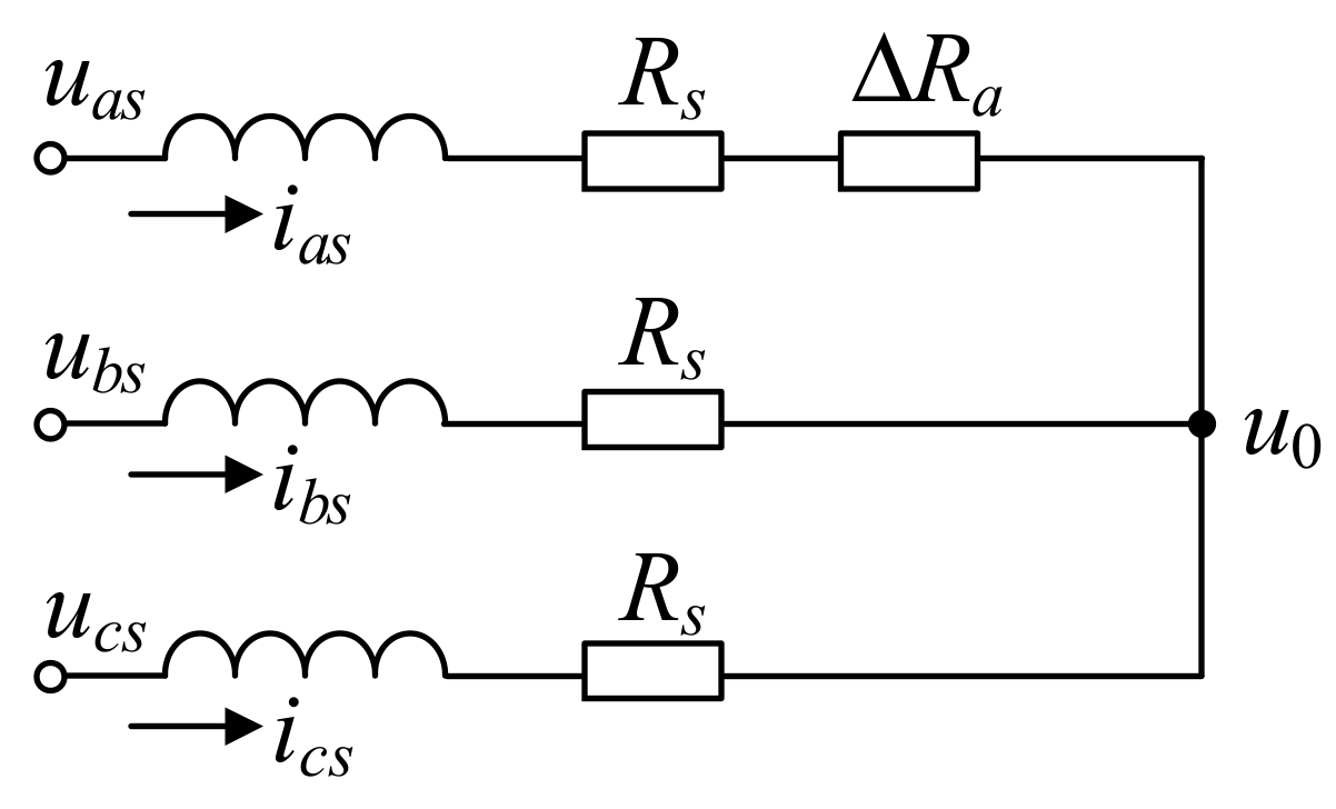
2. DFIG Model with HRC

The HRC in the stator winding of DFIG can be simulated by connecting an additional resistor in series to the faulty phase of the stator winding. It is assumed that the HRC occurs in phase A, as shown in Figure 2.
In Figure 2, uas, ubs, and ucs are the terminal voltages of stator three-phase winding, respectively; u0 is the neutral point voltage of the stator winding; ias, ibs, and ics are the currents of the stator three-phase winding, respectively; Rs is the phase resistance of the stator winding; ∆Ra is the additional resistance in phase A due to the HRC. According to the operating conditions in Figure 2, ignoring the harmonics, the voltage and flux equations of the DFIG with HRC in stator phase A are derived as follows:
u s u r = R s 0 0 R r i s i r + d d t ψ s ψ r + u s 0 0
ψ s ψ r = L s s M s r M s r T L r r i s i r
where [us] and [ur] are the voltage matrices of the stator winding and rotor winding, respectively; [us0] = [u0 u0 u0]T; [is] and [ir] are the current matrices of the stator winding and rotor winding, respectively; [Rs] and [Rr] are the resistance matrices of the stator winding and rotor winding, respectively; [ψs] and [ψr] are the flux matrices of the stator winding and rotor winding, respectively; [Lss] and [Lrr] are the inductance matrices of the stator winding and rotor winding, respectively; and [Msr] is the mutual inductance matrix of the stator and rotor windings. Additionally, their expressions are as follows:
[ u s ] = [ u a s u b s u c s ] T
[ u r ] = [ u a r u b r u c r ] T
[ i s ] = [ i a s i b s i c s ] T
[ i r ] = [ i a r i b r i c r ] T
[ R s ] = R s + Δ R a 0 0 0 R s 0 0 0 R s
[ R r ] = R r 0 0 0 R r 0 0 0 R r
[ L s s ] = L s M s M s M s L s M s M s M s L s
[ L r r ] = L r M r M r M r L r M r M r M r L r
[ M s r ] = L s r cos θ r cos ( θ r + 2 3 π ) cos ( θ r 2 3 π ) cos ( θ r 2 3 π ) cos θ r cos ( θ r + 2 3 π ) cos ( θ r + 2 3 π ) cos ( θ r 2 3 π ) cos θ r
where uar, ubr, and ucr are the terminal voltages of the rotor three-phase winding, respectively; iar, ibr, and icr are the currents of the rotor three-phase winding, respectively; Rr is the phase resistance of the rotor winding; Ls and Ms are the self-inductance and mutual inductance of the stator winding, respectively, and Ms = −1/2 Ls; Lr and Mr are the self-inductance and mutual inductance of the rotor winding, respectively, and Mr = −1/2 Lr; Lsr is the maximum mutual inductance of the stator and rotor windings; and θr is the electrical angle difference of the A-phase winding axis of the stator and rotor, which can be obtained via the following:
θ r = p ω r t + θ 0
where θ0 is the initial electrical angle difference of the A-phase winding axis of the stator and rotor; ωr is the electrical angular velocity of the rotor; and p is the pole-pair number of the DFIG.

3. Diagnostic Method

3.1. Potential Drift of Stator Winding Neutral Point

From the above mathematical model, it can be seen that the HRC of the stator winding did not change the voltage equation of the rotor winding. According to (1) and (7), the HRC leads to three-phase asymmetry in the stator winding, which is directly connected to the power grid, causing the potential drift of the stator winding neutral point. Then, the stator voltage equation can be expressed as follows:
u a s u b s u c s = R s + Δ R a 0 0 0 R s 0 0 0 R s i a s i b s i c s + d d t L s M s M s M s L s M s M s M s L s i a s i b s i c s + e a s e b s e c s + u 0 u 0 u 0
where eas, ebs, and ecs are the stator back-EMFs of the DFIG, which are induced by the three-phase currents of the rotor. It produces the following:
e a s e b s e c s = d d t L s r cos θ r cos ( θ r + 2 3 π ) cos ( θ r 2 3 π ) cos ( θ r 2 3 π ) cos θ r cos ( θ r + 2 3 π ) cos ( θ r + 2 3 π ) cos ( θ r 2 3 π ) cos θ r i a r i b r i c r
Since the rotor winding of the DFIG is driven by the inverter, the rotor currents can be controlled as three-phase symmetrical sinusoidal currents, which can be expressed as follows:
i a r i b r i c r = I r cos ω c t cos ( ω c t 2 3 π ) cos ( ω c t + 2 3 π )
where Ir is the amplitude of rotor current; ωc is the angular frequency of rotor currents. According to the operating principle of the DFIG, it can express the following:
ω s = p ω r + ω c
where ωs is the angular frequency of stator currents. Substituting (12), (15), and (16) into (14) obtains the following:
e a s e b s e c s = 3 2 L s r I r cos ( ω s t + θ 0 ) cos ( ω s t + θ 0 2 3 π ) cos ( ω s t + θ 0 + 2 3 π )
Based on Kirchhoff’s current law, it produces the following:
i a s + i b s + i c s = 0
According to (13), (17), and (18), the potential drift of the stator winding neutral point can be expressed as
u 0 = 1 3 ( u a s + u b s + u c s ) 1 3 Δ R a i a s

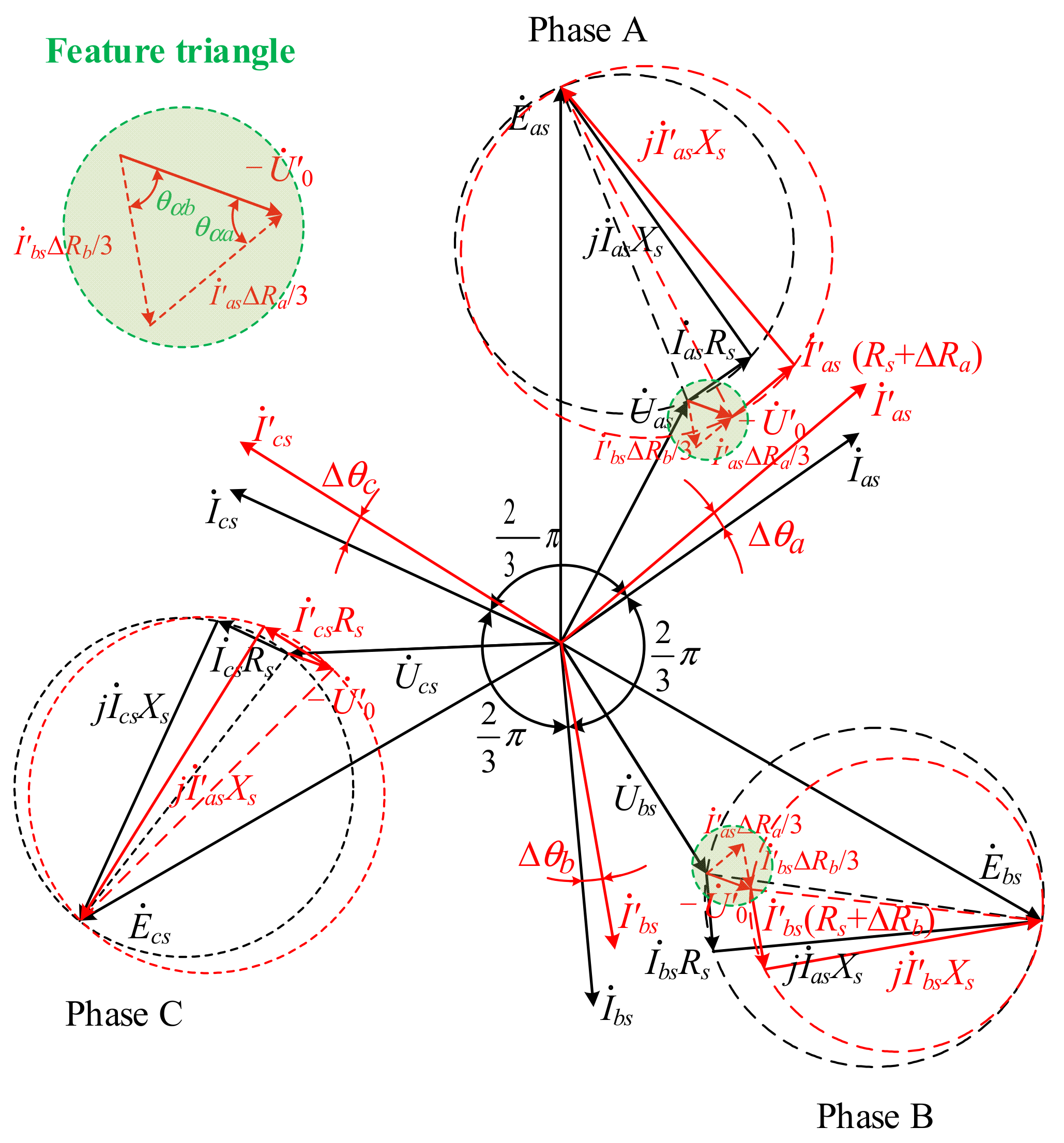
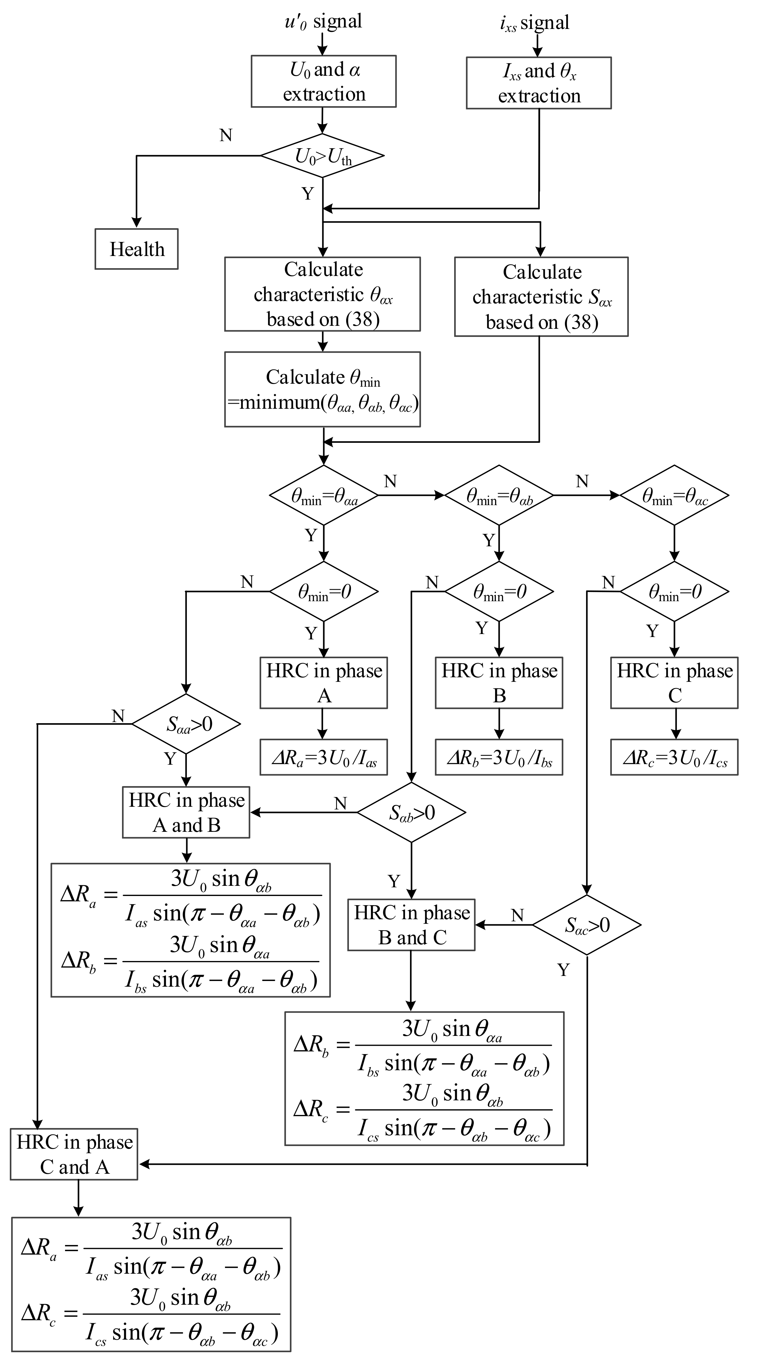
3.2. HRC Diagnosis under Balanced Grid

Since the stator winding of the DFIG is connected to the power grid directly, uas, ubs, and ucs are also the three-phase voltages of the power grid, as shown in Figure 3. In a three-phase balanced grid, it can be expressed as:
u a s + u b s + u c s = 0
When substituting (20) into (19), we can obtain
u 0 = 1 3 Δ R a i a s = 1 3 Δ R a I a s cos ( ω s t + θ a )         = 1 3 Δ R a I a s cos ( ω s t + θ a + π )         = U 0 cos ( ω s t + α )
where Ias and θa are the current amplitude and initial phase of stator A-phase winding, respectively. U0 and α are the voltage amplitude and initial phase of the stator winding neutral point, and
U 0 = 1 3 Δ R a I a s α = θ a + π
From (22), it can be seen that the amplitude and initial phase angle of the neutral point potential u0 are directly related to the amplitude and initial phase angle of the stator fault phase current ias as well as additional resistance ∆Ra.
Similarly, if the HRC occurs in phase B or phase C, it can be obtained as follows:
U 0 = 1 3 Δ R b I b s α = θ b + π   or   U 0 = 1 3 Δ R c I c s α = θ c + π
More generally, when HRC occurs simultaneously in two-phase windings, such as phase A and phase B, it produces the following:
u 0 = Δ R a i a s Δ R b i b s         = 1 3 Δ R a I a s cos ( ω s t + θ a ) 1 3 Δ R b I b s cos ( ω s t + θ b )         = A cos ( ω s t + θ a + π ) + B cos ( ω s t + θ b + π )         = U 0 cos ( ω s t + α )
where
U 0 = A 2 + B 2 + 2 A B     cos ( θ a θ b ) A = 1 3 Δ R a I a s B = 1 3 Δ R b I b s α = arccos ( A   cos ( θ a + π ) + B   cos ( θ b + π ) U 0 )

3.3. Artificial Neutral Point

The above analysis is based on the three-phase balance of the power grid. When the three-phase imbalance occurs in the power grid, (20) is valid, and then (21)~(25) are no longer applicable. In this case, only (19) could be applied to calculate the neutral point potential u0. As can be seen from (19), u0 includes the following two parts: a three-phase imbalance in the power grid and a three-phase imbalance in the stator winding. And then, it is no longer possible to use u0 to determine whether or where HRC occurs. In order to eliminate the impact of the power grid imbalance, an artificial neutral point is constructed to replace the neutral point of the power grid in this paper.
Considering that, in wind power generation systems, three-phase symmetrical capacitor banks are usually connected in parallel to achieve filtering and reactive power compensation functions, their neutral point is easily obtained. Then, the neutral point of the shunt capacitor bank O′ is introduced to replace the neutral point of the power grid O, as shown in Figure 3. The voltage between the two neutral points of the power grid and capacitor bank is uo. Then, the current equation of the shunt capacitor bank can be expressed as follows:
i a c i b c i c c = C d d t u a s u b s u c s u     0 u     0 u     0
where C is the capacitance value in the parallel capacitor bank.
Based on Kirchhoff’s current law, it can be expressed as
i a c + i b c + i c c = 0
Substituting (27) into (26), the following is produced:
u o = 1 3 ( u a s + u b s + u c s ) + K
where K is a constant. In order to ensure that (26) remains true, K must be an invariant constant. And since the initial value of K is 0, it must be 0. Then, the voltage uo′ is as follows:
u o = 1 3 ( u a s + u b s + u c s )
Then, according to (29), the neutral point of the parallel capacitor bank can also be used to detect three-phase unbalanced faults in the grid.
According to (19) and (29), it is expressed as
u     0 = u 0 u o = 1 3 Δ R a i a s
where u0 is the voltage between the two neutral points of the stator winding and shunt capacitor bank. If u0 is used instead of u0 in (21) and (24), (21)~(25) are always correct regardless of whether the three phases of the power grid are balanced or not.

3.4. Fault Location and Degree Estimation
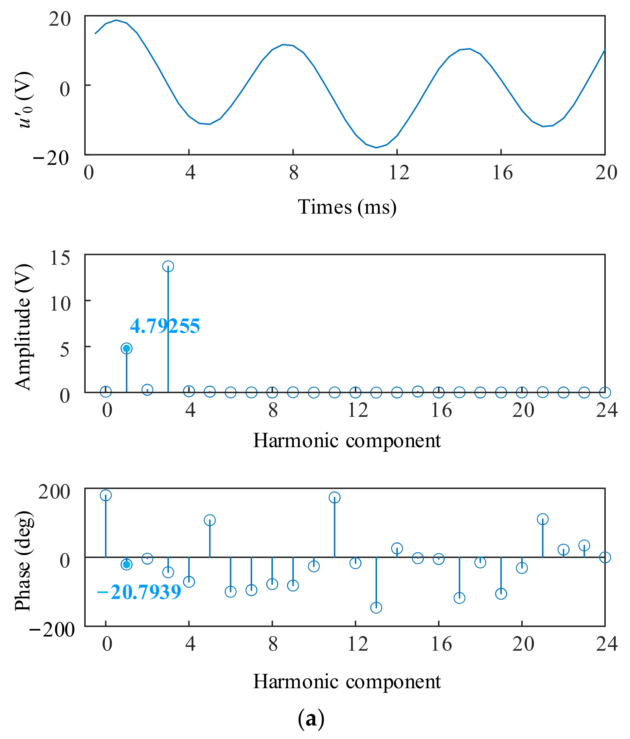
According to the above analysis, the HRC faults can be identified by detecting u0, which is expressed as follows:
u 0 = U 0 cos ( ω s t + α ) U 0 = X 2 + Y 2 + 2 X Y     cos ( θ x θ y ) X = 1 3 Δ R x I x s Y = 1 3 Δ R y I y s α = arccos ( X   cos ( θ x + π ) + Y   cos ( θ y + π ) U 0 )
where x = a, y = b; or x = b, y = c; or x = c, y = a.
Then, when the HRC fault occurs in one phase winding of the stator, u0 can be expressed as follows:
u 0 = U 0 cos ( ω s t + α ) U 0 = X = 1 3 Δ R x I x s α = θ x + π
where x = a, b, or c. It can be seen that an HRC fault in one-phase stator winding can be considered as a special case of the HRC fault in two-phase stator windings. The fault degree and the faulty phase can be conveniently estimated using U0 and α, respectively. If the HRC occurs in all three phase windings of the stator, since the HRC causes an asymmetric fault, the min(∆Ra, ∆Rb, ∆Rc) is considered as part of the normal resistance value of the stator windings, and U0 and α can be calculated as follows:
U 0 = X 2 + Y 2 + 2 X Y     cos ( θ x θ y ) X = 1 3 ( Δ R x Δ R min ) I x s Y = 1 3 ( Δ R y Δ R min ) I y s Δ R min = min ( Δ R a , Δ R b , Δ R c ) α = arccos ( X   cos ( θ x + π ) + Y   cos ( θ y + π ) U 0 )
It can be seen that HRC faults in the three-phase stator winding can be transformed into HRC faults in the two-phase stator winding. Therefore, for the convenience of analysis, whether the fault occurs in a single-phase, two-phase, or three-phase stator winding, it is always assumed that the HRC fault occurs in the two-phase stator winding. Meanwhile, U0 and α are selected as fault characteristics, which can be obtained by gathering the voltage signal between the neutral point N and O′. According to (31)~(33), since the fault phase information cannot be obtained only through α, it is necessary to compare it with the phase of the three-phase stator current and determine the fault location through the phase relationship between u0 and the three-phase stator current. Therefore, θαa, θαb, and θαc are used to replace α as fault characteristics and can directly locate faults based on their values. They can be obtained using the following:
θ α x = α θ x π                                               α θ x π π θ α x = 2 π α θ x π                           α θ x π > π
where x = a, b, or c. Then, by collecting the amplitude and phase of the three-phase stator current, combining (31)~(34), the fault location and degree can be calculated.
In order to achieve rapid fault localization, the range of feature values for different fault phases needs to be analyzed. For the sake of analysis, it is still assumed that phase A is the faulty phase, then according to (32) and (34), θαa = 0, θαb = θaθb, and θαc = θcθa. In the healthy generator system, the three-phase currents are symmetrical, and the phase difference between them is 2π/3. However, in the case of HRC, the three-phase currents are no longer symmetrical, and the phase relationship of 2π/3 between them is no longer satisfied. Figure 4 shows the phasor diagram of the DFIG stator winding with HRC in phase A, where the red font and line segments represent the phasor that changes after the HRC occurs, while the black represents the phasor before the HRC occurs. In Figure 4, similar to the non-salient pole synchronous generator, the synchronous reactance Xs is defined, and expressed as follows:
X s = 3 2 ω s L s
As shown in Figure 4, due to grid clamping, the voltage U ˙ a s , U ˙ b s and U ˙ c s does not change after the HRC fault. According to (17), the EMFs E ˙ a s , E ˙ b s and E ˙ c s do not change using the HRC. Then, three phase voltages E ˙ a s U ˙ a s , E ˙ b s U ˙ b s and E ˙ c s U ˙ c s are still symmetrical after HRC occurs. With them as a reference, it is convenient to calculate the change in the phase and amplitude of three-phase currents after the HRC fault. According to Figure 4, it can be expressed as follows:
Δ θ a = arctan X s R s arctan X s R s + 4 3 Δ R a I a s = R s 2 + X s 2 ( R s + 4 3 Δ R a ) 2 + X s 2 I m Δ θ b = 2 π 3 arcsin 3 3 R s + 4 3 Δ R a + 3 X s ( 6 R s + 9 Δ R a ) 2 + ( 6 X 3 Δ R a ) 2     arctan X s R s + 4 3 Δ R a                                 Δ R a 3 X s R s 2 Δ θ b = arcsin 3 3 R s + 4 3 Δ R a + 3 X s ( 6 R s + 9 Δ R a ) 2 + ( 6 X 3 Δ R a ) 2   arctan X s R s + 4 3 Δ R a π 3                                       Δ R a > 3 X s R s 2 I b s = ( 6 R s + 9 Δ R a ) 2 + ( 6 X 3 Δ R a ) 2 2 ( 3 R s + 4 Δ R a ) 2 + 9 X s 2 I m
Δ θ c = π 3 + arcsin 3 3 R s 4 3 Δ R a + 3 X s ( 6 R s + 9 Δ R a ) 2 + ( 6 X + 3 Δ R a ) 2 arctan X s R s + 4 3 Δ R a                                 Δ R a 3 X s 3 R s 4 Δ θ c = π 3 arcsin 3 3 R s 4 3 Δ R a + 3 X s ( 6 R s + 9 Δ R a ) 2 + ( 6 X + 3 Δ R a ) 2   arctan X s R s + 4 3 Δ R a                             Δ R a > 3 X s 3 R s 4 I c s = ( 6 R s + 9 Δ R a ) 2 + ( 6 X + 3 Δ R a ) 2 2 ( 3 R s + 4 Δ R a ) 2 + 9 X s 2 I m
where ∆θa, ∆θb, and ∆θc are the phase offset of the three-phase stator currents when the HRC fault occurs in phase A. Ias, Ibs, and Ics are the amplitude of the three-phase stator currents of the DFIG with HRC in phase A. Im is the amplitude of the stator currents of the healthy DFIG.
Clearly, with the deepening of the HRC fault, the phase difference between the three-phase fault current and healthy current constantly changes. When HRC occurs in phase A, as the HRC fault deepens, according to (36), ∆θa changes from 0 to arctanXs/Rs, ∆θb changes from 0 to −11π/180, and ∆θc changes from 0 to 11π/180. Meanwhile, ∆θc does not monotonically increase with the increase in the fault severity. As shown in Figure 4, when the degree of fault is very small, ∆θc might be slightly less than 0, and the specific value is determined by the parameters of the DFIG.
According to (36), it can be seen that both the amplitude and phase of the three-phase currents are no longer symmetrical when HRC occurs. The phase fault characteristics can be calculated as follows:
θ α a = 0 θ α b = θ a θ b = arcsin 3 3 R s + 4 3 Δ R a + 3 X s ( 6 R s + 9 Δ R a ) 2 + ( 6 X 3 Δ R a ) 2 + arctan X s R s                                                             Δ R a 3 X s R s 2 θ α b = θ a θ b = π arcsin 3 3 R s + 4 3 Δ R a + 3 X s ( 6 R s + 9 Δ R a ) 2 + ( 6 X 3 Δ R a ) 2   + arctan X s R s                                           Δ R a > 3 X s R s 2 θ α c = θ c θ a = π +   arcsin 3 3 R s 4 3 Δ R a + 3 X s ( 6 R s + 9 Δ R a ) 2 + ( 6 X + 3 Δ R a ) 2   arctan X s R s                                     Δ R a 3 X s 3 R s 4   θ α c = θ c θ a = π arcsin 3 3 R s 4 3 Δ R a + 3 X s ( 6 R s + 9 Δ R a ) 2 + ( 6 X + 3 Δ R a ) 2     arctan X s R s                                       Δ R a > 3 X s 3 R s 4
It can be seen that when HRC occurs in phase A, while only the phase feature quantity θαa has a constant value of 0, and θαb and θαc both change with different degrees of fault. According to (37), θαb is in the range of 2π/3 ≤ θαbπ and θαc is in the range of π-arctanXs/Rsθαc ≤ 229π/180-arctanXs/Rs. Generally, synchronous reactance Xs is much greater than winding resistance Rs, and the range of θαc can be from π/2 to 139π/180. Similarly, the same applies when the HRC occurs in one of the other phases, and θαa, θαb, and θαc only need to be replaced as θαx, θαy, and θαz, respectively, where x is the HRC fault phase, and x, y, z can be a, b, c, or b, c, a or c, a, b. Then, the faulty phase can be identified by calculating the phase fault characteristics θαa, θαb, and θαc since only the fault phase feature quantity θαx is a constant value of 0. It is a very simple and effective method for a one-phase HRC fault. When HRC occurs in two phases, such as phases A and B, there is no longer a constant characteristic quantity, and this method cannot be directly applied. In this situation, it is necessary to reanalyze its phase change and discover reliable patterns that can be used to locate the faulty phase.
Figure 5 shows the phasor diagram of DFIG stator winding with HRC in phases A and B. In Figure 5, a feature triangle is constructed both in two fault phases to help identify the pattern of phase feature quantities. It can be seen that, affected by the lagging fault phase, the current of the leading phase A leads by U ˙ 0 a certain angle θαa. Similarly, the current of the lagging phase B lags behind U ˙ 0 a certain angle θαb. At least one out of θαa and θαb is an acute angle, and one of them is the smallest of θαa, θαb and θαc, which depends on the degree of fault in both phases. U ˙ 0 is located between the leading and lagging phase currents. Then, one fault phase can be determined by finding the minimum phase characteristic quantity. By combining the phase relationship between the current of this phase and U ˙ 0 , either leading or lagging, another faulty phase can be identified. For example, when calculating, θαb is the smallest of the three feature quantities and I ˙ b s leads by U ˙ 0 ; then, the two fault phases are phases B and C. Otherwise, the two fault phases are phases A and B. If there are two equal minimum feature quantities, the corresponding two phases are the fault phase, as shown in Figure 5. In this situation, the phase difference between I ˙ a s and I ˙ b s is 2π/3, and θαa = θαb = π/3. Affected by the lagging fault phase, I ˙ a s is larger than I ˙ b s , and ∆Ra < ∆Rb.
θαx is the magnitude of the phase difference between U ˙ 0 and I ˙ x s . Through the above analysis, in order to accurately locate the faulty phase, not only the magnitude of the phase difference needs to be calculated, but also its sign needs to be determined. For the convenience of application, (34) has been modified as follows:
θ α x = θ x α + π ,         S α x = θ x α + π θ x α + π                                                           θ x α π [ 2 π , π ] θ α x = θ x α π ,         S α x = θ x α π θ x α π                                                             θ x α π [ π , π ] θ α x = θ x α 3 π ,         S α x = θ x α 3 π θ x α 3 π                                                       θ x α π [ π , 2 π ] α [ π , π ] θ x [ 0 , 2 π ] S α x = 1 ,                   i f   θ α x = 0
where x = a, b, or c, α is the extracted initial phase of U ˙ 0 and θαx is the extracted initial phase of I ˙ x s . When the HRC occurs in one phase, the additional resistance ΔRx can be obtained using (32) as follows:
Δ R x = 3 U 0 I x s
When the HRC occurs in two phases, the additional resistance ΔRx and ΔRy can be obtained using the feature triangle as follows:
Δ R x = 3 U 0 sin θ α y I x s sin ( π θ α x θ α y ) Δ R y = 3 U 0 sin θ α x I y s sin ( π θ α x θ α y )
Then, the flowchart of the HRC diagnosis process is provided in Figure 6. The online HRC fault diagnosis process is as follows:
Step 1: HRC fault detection. The fundamental components of u0 and ixs are extracted online. Then, once the amplitude U0 is larger than 0, the HRC fault can be detected.
Step 2: Fault phase location. After detecting the occurrence of HRC, HRC fault characteristics θαx and Sαx are calculated based on (38). Then, according to the minimum of θαx and combined with the sign of Sαx, the fault phase can be located.
Step 3: Fault severity estimation. After locating the fault phase, the additional resistance ΔRx can be calculated based on (39) or (40).

4. Simulations

In order to verify the effectiveness of the proposed method and ensure the reliability of the simulation results, the complex electromagnetic environment of the DFIG should be simulated realistically. Then, considering the impact of complex electromagnetic fields on fault diagnosis, a finite element (FE) model of DFIG can be established alongside the external circuit model based on the field-circuit coupling method, as shown in Figure 7. The main parameters of the FE model are shown in Table 1.
Figure 8 shows the waveform and harmonic components of the voltage u0 in the healthy DFIG. It can be seen that, in the healthy DFIG, the main component of u0 is the third harmonic component, and the fundamental component is very small and almost non-existent. As shown in Figure 7b, an additional resistor ∆R = 0.2 Ω is connected in series with A-phase winding, and the resistance of A-phase winding in a healthy state is 0.2 Ω. Then, the simulation results are shown in Figure 9. Compared with Figure 8, the fundamental component appears in the voltage u0, where U0 = 4.79255 V and α = −20.7939°, as shown in Figure 9a. From Figure 9b, it can be seen that θa = 159.358° and Ias =73.1161 A before θαa = |θaα − π| = 0 is obtained. According to the proposed diagnosis method, the HRC fault is in A-phase winding, and according to (39), the additional resistance ΔRa can be calculated as ΔRa = 3U0/Ias = 0.19664 Ω. So, the proposed diagnosis method is effective for HRC in the one-phase stator winding of the DFIG.
Figure 10 shows the simulation results when HRC occurs in phase A and phase B, where ∆Ra = ∆Rb = 0.2 Ω. From Figure 10, it is shown that U0 = 4.80292 V, α = −81.817°, Ias = 71.8809 A, Ibs = 74.1309 A, Ics = 73.2912 A, θa = 159.812°, θb = 40.0469°, and θc = −81.5924°. According to (38), θαa = |θaα − π| = 61.629°, Sαa = 1, θαb = |θbα − π| = 58.1361°, Sαb = −1, θαc = |θcα − π| = 179.7754°, and Sαc = −1. Then, θmin = θαb, and Sαb < 0. According to Figure 6, the HRC fault is in phases A and B. According to (40), it is shown that ΔRa = 0.19612 Ω and ΔRb = 0.19702 Ω. It can be seen that the error of the proposed diagnosis method is only 1.49%, which is a high accuracy.
Figure 11 shows the simulation results when HRC occurs in phase A and phase B, and the degree of fault between phase A and phase B is different, where ∆Ra = 0.2 Ω, ∆Rb = 0.5 Ω. From Figure 11, it is shown that U0 = 10.7089 V, α = −114.52°, Ias = 69.9473 A, Ibs = 73.3283 A, Ics = 74.6458 A, θa = 160.449°, θb = 43.1946°, and θc = −80.3946°. It can be seen that U0 in Figure 11 is greater than that in Figure 10 since the fault degree in Figure 11 is greater than that in Figure 10. According to (38), θαa = |θaα − π| = 94.969°, Sαa = 1, θαb = |θbα − π| = 22.2854°, Sαb = −1, θαc = |θcα − π| = 145.8746°, Sαc = −1. Then, θmin = θαb and Sαb < 0. According to Figure 6, the HRC fault is in phases A and B. According to (40), it has ΔRa = 0.1959 Ω and ΔRb = 0.5147 Ω. It can be seen that the HRC in phases A and B can be accurately diagnosed.
Figure 12 shows the simulation results when HRC occurs in phase A and phase C, and the degree of fault between phase A and phase C is different, where ∆Ra = 0.2 Ω, ∆Rc = 0.5 Ω. From Figure 12, it is shown that U0 = 9.96105 V, α = 77.967°, Ias = 75.3756 A, Ibs = 71.5241 A, Ics = 71.1704 A, θa = 161.3°, θb = 39.1857°, and θc = −77.043°. According to (38), θαa = |θaα − π| = 96.667°, Sαa = −1, θαb = |θbα + π| = 141.2187°, Sαb = 1, θαc = |θcα − π| = 24.99°, Sαc = 1. Then, θmin = θαc and Sαb > 0. According to Figure 6, the HRC fault is in phases A and C. According to (40), it has ΔRa = 0.1968 Ω and ΔRb = 0.4875 Ω. The HRC in phases A and B can also be accurately diagnosed. So, the proposed diagnosis method is effective for HRC in two-phase stator windings of the DFIG.

5. Discussion of Results

Based on the above simulation analysis, it can be seen that the method proposed in this article cannot only achieve an accurate fault degree evaluation and fault location of single-phase faults but can also accurately locate the fault phase of two-phase faults, and accurately evaluate the fault degree of each phase. The methods in [10,11] can only achieve accurate fault diagnosis for single-phase faults, and, for two-phase faults, only an approximate fault degree could be estimated, where the fault degree judged by this method was the same for two-phase faults, and it could not evaluate the faults of each phase separately. Meanwhile, from the processing flow, it can be seen that the proposed method was relatively simple compared to other signal processing-based methods [12,13]. Moreover, its diagnostic process does not rely on precise DFIG models like [4,14], but it has a stronger anti-interference ability. And compared to knowledge-based methods [16,17], it does not need to rely on a large number of samples, it is not affected by the training model, and can achieve high-precision fault diagnosis at a small cost.
The above analysis is based on a simulation, and there may be some differences between the experimental results and simulation results. Firstly, the inherent asymmetry of the generator itself can cause the average value of the sliding window to be greater than zero under normal circumstances. Therefore, in practical situations, appropriate thresholds should be selected to avoid the misdiagnosis caused by inherent asymmetry. Secondly, in practice, there may be measurement interferences in voltage sensors and current sensors, which leads to certain burrs in the actual phase information and affects the accuracy of fault assessment, but it does not have a significant impact on fault location.

6. Conclusions and Future Work

This paper proposes a new method for the online diagnosis of DFIGs stator winding HRC faults using artificial neutral points constructed using parallel capacitor banks. Based on the analysis of the mathematical model of DFIG with HRC in stator winding, the fault feature quantities are defined, and the HRC fault is diagnosed based on the fault feature quantities. Finally, the simulations are conducted to verify the effectiveness and correctness of the theoretical analysis. The research content of this paper is summarized as follows:
(1)
The interference and false alarms caused by power grid imbalance can be eliminated through the method of constructing an artificial neutral point, as proposed in this paper.
(2)
The proposed method can accurately locate the faulty phase and evaluate the degree of the fault in the case of single-phase faults, with an evaluation accuracy of over 98%.
(3)
In the case of faults occurring in two phases, regardless of whether the faults are the same or not, the proposed method can accurately locate the faulty phase and evaluate the degree of fault in each phase, with an evaluation accuracy of over 97%.
The proposed method is based on the assumption of an excellent control performance. The next step, the impact of different control methods and control performance, needs to be analytically researched. Meanwhile, considering the feasibility of the application of this method in rotor winding fault diagnosis, a classification method for diagnosing HRC faults in stator and rotor windings should be studied.

Author Contributions

Conceptualization, W.D. and Y.J. (Yulong Jin); methodology, W.D., Y.J. (Yulong Jin), X.W., Y.Y. and Y.J. (Yongjiang Jiang); validation, X.W., Y.Y. and Y.J. (Yongjiang Jiang); formal analysis, W.D. and Y.J. (Yulong Jin); investigation, Y.J. (Yongjiang Jiang) and X.W.; writing—original draft preparation, W.D. and Y.J. (Yulong Jin); writing—review and editing, X.W., Y.Y. and Y.J. (Yongjiang Jiang); supervision, Y.J. (Yulong Jin) and X.W; project administration, Y.J. (Yulong Jin); funding acquisition, Y.Y. All authors have read and agreed to the published version of the manuscript.

Funding

This research was funded by the Research and Application of Key Technologies for Centralized Control Operation and Maintenance of New Energy, grant number 524609220028.

Data Availability Statement

Data are contained within the article.

Conflicts of Interest

The authors declare no conflict of interest.

References

  1. Hang, J.; Xia, M.; Ding, S.; Li, Y.; Sun, L. Research on vector control strategy of surface-mounted permanent magnet synchronous machine drive system with high-resistance connection. IEEE Trans. Power Electron. 2020, 35, 2023–2033. [Google Scholar] [CrossRef]
  2. Hang, J.; Ren, X.; Tang, C.; Tong, M. Fault-tolerant control strategy for five-phase PMSM drive system with high-resistance connection. IEEE Trans. Transp. Electrific. 2021, 7, 1390–1400. [Google Scholar] [CrossRef]
  3. Xu, Z.; Din, Z.; Jiang, Y.; Cheema, K.M.; Milyani, A.H.; Alghamdi, S. High-resistance connection diagnosis considering current closed-loop effect for permanent magnet machine. Front. Energy Res. 2022, 10, 933246. [Google Scholar] [CrossRef]
  4. Gonçalves, P.F.C.; Cruz, S.M.A.; Mendes, A.M.S. Online diagnostic method for the detection of high-resistance connections and open-phase faults in six-phase PMSM drives. IEEE Trans. Ind. Appl. 2022, 58, 345–355. [Google Scholar] [CrossRef]
  5. Rossi, C.; Gritli, Y.; Pilati, A.; Rizzoli, G.; Tani, A.; Casadei, D. High resistance fault-detection and fault-tolerance for asymmetrical six-phase surface-mounted AC permanent magnet synchronous motor drives. Energies 2020, 13, 3089. [Google Scholar] [CrossRef]
  6. Zamudio-Ramirez, I.; Antonino-Daviu, J.A.; Osornio-Rios, R.A.; de Jesus Romero-Troncoso, R.; Razik, H. Detection of winding asymmetries in wound-rotor induction motors via transient analysis of the external magnetic field. IEEE Trans. Ind. Electron. 2020, 67, 5050–5059. [Google Scholar]
  7. Zamudio-Ramirez, I.; Antonino-Daviu, J.A.; Osornio-Rios, R.A.; Dunai, L. Tracking of high-order stray-flux harmonics under starting for the detection of winding asymmetries in wound-rotor induction motors. IEEE Trans. Ind. Electron. 2022, 69, 8463–8471. [Google Scholar] [CrossRef]
  8. Zamudio-Ramirez, I.; Antonino-Daviu, J.; Osornio-Rios, R.A.; Dunai, L.; Quijano-Lopez, A.; Fuster-Roig, V. Detection of stator asymmetries in wound rotor induction motors through the advanced analysis of rotor currents. In Proceedings of the 2022 IEEE Energy Conversion Congress and Exposition (ECCE), Detroit, MI, USA, 9–13 October 2022. [Google Scholar]
  9. Martínez, M.E.I.; Antonino-Daviu, J.A.; de Córdoba, P.F.; Conejero, J.A.; Dunai, L. Automatic classification of winding asymmetries in wound rotor induction motors based on bicoherence and fuzzy c-means algorithms of stray flux signals. IEEE Trans. Ind. Appl. 2021, 57, 5876–5886. [Google Scholar] [CrossRef]
  10. Wang, H.; Lu, S.; Qian, G.; Ding, J.; Liu, Y.; Wang, Q. A two-step strategy for online fault detection of high-resistance connection in bldc motor. IEEE Trans. Power Electron. 2020, 35, 3043–3053. [Google Scholar] [CrossRef]
  11. Hang, J.; Yan, D.; Xia, M.; Ding, S.; Wang, Q. Quantitative fault severity estimation for high-resistance connection in PMSM drive system. IEEE Access 2019, 7, 26855–26866. [Google Scholar] [CrossRef]
  12. Hu, R.; Wang, J.; Mills, A.R.; Chong, E.; Sun, Z. Detection and classification of turn fault and high resistance connection fault in permanent magnet machines based on zero sequence voltage. IEEE Trans. Power Electron. 2020, 35, 1922–1933. [Google Scholar] [CrossRef]
  13. Hang, J.; Wu, H.; Ding, S.; Hua, W.; Wang, Q. A DC-flux-injection method for fault diagnosis of high-resistance connection in direct-torque-controlled PMSM drive system. IEEE Trans. Power Electron. 2020, 35, 3029–3042. [Google Scholar] [CrossRef]
  14. Hang, J.; Zhang, J.; Ding, S.; Huang, Y.; Wang, Q. A model-based strategy with robust parameter mismatch for online HRC diagnosis and location in PMSM drive system. IEEE Trans. Power Electron. 2020, 35, 10917–10929. [Google Scholar] [CrossRef]
  15. Kommuri, S.K.; Park, Y.; Bin Lee, S. High-resistance fault control in permanent magnet synchronous motors. IEEE/ASME Trans. Mech. 2019, 25, 271–281. [Google Scholar] [CrossRef]
  16. Lee, H.; Jeong, H.; Koo, G.; Ban, J.; Kim, S.W. Attention Recurrent Neural Network-Based Severity Estimation Method for Interturn Short-Circuit Fault in Permanent Magnet Synchronous Machines. IEEE Trans. Ind. Electron. 2021, 68, 3445–3453. [Google Scholar] [CrossRef]
  17. Li, Y.; Wang, R.; Mao, R.; Zhang, Y.; Zhu, K.; Li, Y.; Zhang, J. A Fault Diagnosis Method Based on an Improved Deep Q-Network for the Inter-Turn Short Circuits of a Permanent Magnet Synchronous Motor. IEEE Trans. Ind. Electron. 2023, in press. [Google Scholar] [CrossRef]
  18. Faiz, J.; Abadi, M.B.; Cruz, S.M.; Moosavi, S.M.M. Comparison of rotor electrical fault indices owing to inter-turn short circuit and unbalanced resistance in doubly-fed induction generator. IET Electr. Power App. 2019, 13, 235–242. [Google Scholar]
  19. Battulga, B.; Shaikh, M.F.; Bin Lee, S.; Osama, M. Automated identification of failures in doubly-fed induction generators for wind turbine applications. IEEE Trans. Ind. Appl. 2023, 59, 4454–4463. [Google Scholar] [CrossRef]
  20. Ibrahim, R.K.; Watson, S.J.; Djurović, S.; Crabtree, C.J. An effective approach for rotor electrical asymmetry detection in wind turbine DFIGs. IEEE Trans. Ind. Electron. 2018, 65, 8872–8881. [Google Scholar] [CrossRef]
  21. Fu, Y.; Ren, Z.; Wei, S.; Xu, Y.; Li, F. Using flux linkage difference vector in early inter-turn short circuit detection for the windings of offshore wind DFIGs. IEEE Trans. Energy Convers. 2021, 36, 3007–3015. [Google Scholar] [CrossRef]
Figure 1. HRC fault mechanism of DFIG.
Energies 16 07516 g001
Figure 2. Equivalent model of DFIG stator winding with the HRC in phase A.
Energies 16 07516 g002
Figure 3. Connection diagram of DFIG stator winding.
Energies 16 07516 g003
Figure 4. Phasor diagram of DFIG stator winding with HRC in phase A.
Energies 16 07516 g004
Figure 5. Phasor diagram of DFIG stator winding with HRC in phase A and B.
Energies 16 07516 g005
Figure 6. Flow chart of HRC diagnosis process.
Energies 16 07516 g006
Figure 7. Field-circuit coupling model of DFIG. (a) FE simulation model; (b) External circuit.
Energies 16 07516 g007
Figure 8. u0 of the healthy DFIG.
Energies 16 07516 g008
Figure 9. u0 and stator currents of the DFIG with HRC in phase A. (a) u0; (b) Stator currents.
Energies 16 07516 g009aEnergies 16 07516 g009b
Figure 10. u0 and stator currents of the DFIG with HRC in phase A and B. (∆Ra = ∆Rb = 0.2 Ω) (a) u0; (b) Stator currents.
Energies 16 07516 g010
Figure 11. u0 and stator currents of the DFIG with HRC in phase A and B. (∆Ra = 0.2 Ω, ∆Rb = 0.5 Ω) (a) u0; (b) Stator currents.
Energies 16 07516 g011aEnergies 16 07516 g011b
Figure 12. u0 and stator currents of the DFIG with HRC in phase A and C. (∆Ra = 0.2 Ω, ∆Rc = 0.5 Ω) (a) u0; (b) Stator currents.
Energies 16 07516 g012
Table 1. FE Model parameters of DFIG.
ItemValueItemValue
Rated power [kW]1500Rated speed [rpm]1750
Stator outer diameter [mm]860Stack length [mm]780
Stator inner diameter [mm]615Pole-pair number2
Thickness of stator yoke [mm]93.5Number of stator slot72
Tooth width of stator [mm]14Number of rotor slot96
Rotor outer diameter [mm]611.4Number of stator winding layers2
Rotor inner diameter [mm]200Number of rotor winding layers2
Thickness of rotor yoke [mm]122.5Stator coil pitch16
Tooth width of rotor [mm]9.3Rotor coil pitch20
Disclaimer/Publisher’s Note: The statements, opinions and data contained in all publications are solely those of the individual author(s) and contributor(s) and not of MDPI and/or the editor(s). MDPI and/or the editor(s) disclaim responsibility for any injury to people or property resulting from any ideas, methods, instructions or products referred to in the content.

