Abstract
This research study investigated the transient behavior of the convection–diffusion model for the infiltration heat recovery (IHR) and the influence of the building envelope heat capacity, along with other factors. A transient numerical model was developed and validated to analyze the IHR under various conditions. The results highlight the role of heat capacity, thermal conductivity, wall thickness, airflow rate, airflow direction, and wall porosity on the temperature distribution and the heat recovery factor within the wall. Higher-heat-capacity walls displayed a delayed temperature rise, while low-thermal-conductivity walls reduced the conduction heat transfer and increased the IHR factor. The impact of heat capacity diminished with very low thermal conductivity walls but became evident for high-thermal-conductivity walls, particularly at higher Peclet numbers. Thicker walls enhanced the heat retention and improved the IHR, with a reduced influence of airflow rate. Higher IHR factors were associated with thicker walls, lower Peclet numbers, and higher heat capacities. The analysis also showed that the wall porosity affected the IHR with less significance than the other factors. Incorporating these findings into building energy modeling tools could improve the prediction accuracy of the thermal behavior of buildings. Accordingly, this study contributes to building physics by understanding IHR dynamics and thermal mass interactions, as well as improving building energy modeling accuracy for performance prediction. Future research can explore the impacts of additional factors on IHR and investigate the effect of IHR on the overall energy consumption of buildings.
1. Introduction
Air leakage is one of the major sources of energy gain and loss in buildings. Typically, the pressure gradient induced by wind blowing on the sides of a building can cause air to enter the building on the windward side and exit on the leeward side, resulting in the significant energy consumption of buildings. Traditionally, the energy impact of infiltration has been calculated based on the infiltration flow rate and the enthalpy difference between indoor and outdoor air [1]. However, this calculation method assumes that the air entering the building remains unchanged as it passes through the building envelope. Therefore, standard methods of calculating infiltration ignore the thermal coupling between infiltration and conduction heat transfer through the building envelope, leading to potentially inaccurate estimations of heating and cooling loads.
On the other hand, the exchange of heat between infiltrating (or exfiltrating) air and building envelope materials is referred to as infiltration heat recovery (IHR). This exchange results in a reduction in the impact that the infiltrating air has on the energy required to condition the building. As the infiltrating air passes through the envelope, it exchanges heat with the materials, causing the air entering the building to be at a temperature that is not equal to that of the outdoor environment. Additionally, the air leaving the building tends to bring the interior surface closer to the indoor temperature, thereby reducing the heat transfer through the envelope [2]. In essence, the building envelope functions as a heat exchanger for infiltrating and exfiltrating air, resulting in a net reduction in the energy impact of the airflow. Hence, the thermal properties of the building envelope could be considered as one of the main factors that influence the heat exchange performance of IHR. This heat recovery effect can reduce energy consumption in some climates. One study indicated that IHR is responsible for reducing the thermal load of infiltration by 10% to 20% in cold climates [3].
Additionally, the direction and amount of airflow, whether from warm to cold or vice versa, significantly impacts the temperature gradient within the wall. In heating climates, infiltration refers to cold air entering a warm space. As the amount of airflow increases, the effects of infiltration heat recovery cause the gradient to become more convex. This results in a lower impact of infiltration energy due to a lower overall wall temperature but an increase in conduction due to a steeper temperature gradient. Conversely, in cooling climates, warm air enters a cooler space, creating a concave temperature gradient within the wall with increasing airflow and decreasing conduction [4].
Recent studies, both experimental and numerical, highlighted the presence of significant thermal coupling between air leakage and wall elements, leading to modifications in heat transmission. Furthermore, several models were developed to investigate the behavior of IHR, for instance, Anderlind [5] created a basic model to assess the thermal coupling between air infiltration and heat conduction in a wall. The model assumes that the infiltration is uniformly distributed across the wall surface. Liu [6] developed a model that considers the influence of solar gains on infiltration heat recovery. The effect of solar heat transfer is believed to be magnified by changes in the exterior surface air temperature. When the solar gains are not considered, the solution provided by the Liu model is equivalent to that of the Anderlind model. Moreover, Krarti [7] presented an analytical steady-state model of the IHR that considers heat convection along wall surfaces and assumes that diffuse air enters the wall at the surface temperature rather than the ambient temperature. The study concluded that temperature profiles and heat flux along the inner and outer wall surfaces demonstrate the effect of airflow on heat transmission through building envelopes. In addition, Buchanan and Sherman [8] proposed a model with a wall participation factor to account for air leakage only happening in a portion of the wall area, which decreases the infiltration heat recovery effect as the wall participation factor decreases. The study conducted a thorough numerical analysis of the heat exchange between the wall and infiltration, utilizing both two-dimensional and three-dimensional simulations and validating their results with experimental data. Later, Solupe and Krarti [3] discussed the implementation of the steady-state infiltration heat recovery (IHR) models mentioned above. Inter-model and experimental comparisons were performed to assess the accuracy of the predictions of these models. Sensitivity analyses were performed and showed that implementing IHR models in a whole-building simulation environment reduced heating consumption by 5% to 30% for four audited residential homes.
Conversely, Solupe [4] conducted a thorough assessment of IHR, revealing a prevalent issue with most IHR models: they are represented by the absence of information concerning the quantity of diffuse airflow and the factor of IHR that normally occurs within a wall. The study stated that the flow exponent from a blower door test can be used to characterize airflow through an envelope and estimate infiltration heat recovery. A higher flow exponent indicates that building air leakage has more diffuse characteristics, potentially resulting in greater infiltration heat recovery. Nevertheless, several researchers, such as Buchanan and Sherman [8], Abadie et al. [9], and Qiu and Haghighat [10], used computational fluid dynamics (CFD) models to calculate the IHR factor. However, this method can be computationally expensive in terms of CPU time. Similarly, Sherman and Walker [2] worked on improving the prediction of energy load due to infiltration by introducing a correction factor that multiplies the expression for the conventional load. The study included simplified analytical modeling and CFD simulations to examine the infiltration heat recovery (IHR) effect on typical building envelopes. The results of the study show that IHR is negligible in buildings with insulated walls due to the small fraction of the envelope that participates in heat exchange with the infiltrating air. However, higher participation in dynamic walls/ceilings or uninsulated walls has the potential for a significant IHR effect. Later, in a recent study, Tallet et al. [11] introduced a reduced-order model (ROM) technique that uses proper orthogonal decomposition (POD) to analyze the impact of energy balance permeability in buildings. The proposed ROM was developed in Modelica and applied to a case study that focused on air infiltration in a low-energy-consumption building. The results demonstrate the ROM approach’s effectiveness in evaluating buildings’ energy performance. It should be noted that in the steady-state analysis of IHR, as with the analysis presented in most previous studies, energy is neither created nor stored within the wall, and the temperature derived defines the conditions of the wall and air, assuming local thermal equilibrium.
On the other hand, several experimental studies were conducted to evaluate the thermal coupling of infiltration and heat conduction in walls. One of the first experiments in this area was conducted by Bhattacharyya and Claridge [12]. In this experiment, the heat exchange between infiltrating air and an insulated test cell was studied, and it showed that heat conducting through the envelope of a building can warm the air that is leaking into the building, resulting in an infiltration energy loss that is less than the enthalpy difference between the inside and outside air. The experimental study also stated that infiltration heat exchange effectiveness strongly depends on three variables: flow rate, path length, and hole size. The results of the study show that infiltration heat recovery is higher at lower flow rates and lower at higher flow rates. Furthermore, Janssens [13] presented a hot box experiment to investigate the heat recovery effect for air infiltration through a crack in an insulated wall. The experiment used a two-dimensional calculation model for combined heat and mass transfer to measure the steady-state transmission and infiltration heat loss through a wall. The experiment also employed a tracer gas technique to measure the infiltration flow rate. Numerical simulations were carried out to derive the proper test conditions and the results of the experiment were used to determine the infiltration heat recovery effectiveness by comparing the measured transmission and infiltration losses to the steady-state transmission loss through the wall with sealed cracks. Moreover, Ackerman et al. [14] conducted a laboratory experiment to investigate the effect of airflow through a wall test panel. Two identical panels were constructed using a wood frame, fiberglass insulation, plywood, and gypsum. The panels were designed with specific entry and exit points through the gypsum and plywood, enabling air to flow through the insulation. The experiment showed that the heat recovery potential of infiltration strongly depends on the heat exchange participation fraction of the building envelope. Finally, in the most recent experiment conducted for IHR, Brownell [15] examined the relationship between heat loss and infiltration flow rate in a test cell, focusing on the high flow rate regime. A 3.5 m3 test cell was constructed using standard light-frame construction and a removable panel to test wall sections with varying flow path lengths. Two different wall sections were tested, and six different infiltration flow rates were utilized. The study compared experimentally determined heat recovery factors to computational fluid dynamics, and the results were consistent within an approximate 15% margin of error.
Breathing walls are construction elements made of porous materials that serve as insulation components and heat recovery exchangers [16]. Wall porosity is a fundamental property of materials; it describes the proportion of void space within the material’s volume. This void space can permit the passage of air. In the context of building materials, porosity can influence the thermal and ventilation properties of walls. On the other hand, a breathing wall is a term often used to describe walls with intentionally high porosity that are designed for specific purposes. These walls allow for regulated air movement, facilitating natural ventilation and potentially contributing to the building’s thermal performance. It is essential to understand that while all breathing walls exhibit high porosity, not all walls with high porosity are designed or function as breathing walls.
The concept of air-permeable concrete (APC) was also introduced as a dynamic breathing wall system [17]. Breathing walls, often referred to as permodynamic walls, have been extensively studied, especially the coupling effect between air leakage and conduction heat transfer through the wall. A recent review paper presented by Fawaier and Bokor [18] classified and discussed various studies on dynamic insulation structures, highlighting the use of breathing walls to enhance indoor air quality and minimize the cooling or heating energy in buildings. Recent research studies focused on the performance of breathing walls. For example, Zhang and Wang [19] analyzed the critical insulation thickness of breathing walls under different scenarios to minimize the pressure drop and reduce convective heat loss. Alongi et al. [20] developed a steady periodic analytical model for breathing walls. They validated the model with experimental data by investigating temperature profiles and heat flux across sample wall blocks at varying air velocities. Zhang et al. [21] developed and validated a network heat transfer model for exhaust air insulation walls (EAIWs) to optimize their design and increase the energy-saving potential for different climates. Alongi et al. [22] presented a one-dimensional numerical model of breathing walls using the finite difference method, validating it with experimental data and dynamic analytical models under sinusoidal and periodic boundary conditions. The study examined the wall’s temperature distribution and heat flux for different air velocities and time durations. Alongi et al. [23] investigated the optimal operation strategies for breathing walls using a transient numerical model coupled with TRNSYS. They analyzed the energy savings of an office room in Milan, Italy.
While IHR has been explored extensively, as discussed above, most research studies have focused on the steady-state performance of IHR while ignoring the thermal energy storage of the wall. Only a few studies investigated the IHR transient effect of dynamic insulation breathing walls. However, no research studies were found that evaluated the heat recovery factor of the wall in the context of the transient behavior of the convection-diffusion model of the IHR phenomena. Specifically, the interrelationship effects between the wall’s thermal conductivity, thermal mass, airflow rate, airflow direction, wall thickness, and wall porosity concerning the heat recovery factor have not been adequately analyzed. Therefore, this study aimed to fill this research gap by developing and analyzing a transient convection–diffusion numerical model representing the IHR phenomena and investigating the impact of the heat capacity of the building’s exterior walls on the performance of IHR under various conditions. The findings of this study will provide insights into the transient behavior of IHR for various design conditions and contribute to the ongoing efforts to improve the modeling accuracy of building physics.
To provide a comprehensive understanding of the study’s approach and findings, this paper is structured as follows: Section 2 details the “Materials and Methods,” encompassing the analysis methods employed, the transient and steady-state IHR models, and the derivation of the heat recovery factor. In Section 3, “Results and Discussion” are presented. This section provides an in-depth look into the analysis of the temperature distribution within the wall, discussing the effects of heat capacity (HC) and airflow rate under varying conditions, alongside an extensive analysis of the infiltration heat recovery (IHR) factor, exploring its relationship with parameters, such as the Peclet number (Pe), heat capacity, wall thickness, and wall porosity. Finally, Section 4 concludes the study, summarizing the key findings and their implications.
2. Materials and Methods
2.1. Analysis Methods
The objective of this research study was to provide a detailed understanding of the impact of the building’s thermal mass on IHR performance by investigating the transient effect of the wall’s heat capacity on the performance of infiltration heat recovery for various conditions. It is important to note that most investigations into IHR have mainly focused on its performance in the context of porous insulation materials, which are recognized for their low thermal conductivity and minimal thermal mass. Consequently, one of the principal objectives of this research study was to expand the analysis of IHR to include broader wall systems while considering the impact of both thermal conductivity and heat capacity.
As documented in the prior research studies discussed earlier, the steady-state convection–diffusion IHR model is employed to analyze the temperature distribution within the wall and determine the heat recovery factor of dynamic or porous insulation walls. As explored in these studies, temperature profiles within the wall are altered due to the influence of air leakage through the wall. The amount of this distortion of temperature distribution depends on the rate of airflow and the direction of the air leakage within the wall (i.e., infiltration or exfiltration). In the absence of airflow leakage, a linear steady-state profile is observed. However, in the case of infiltration, or the movement of air through the wall from outdoors to indoors, a concave temperature distribution is observed within the wall, which influences the level of heat gain due to conduction heat transfer through the wall. The opposite effect is observed when the direction of air leakage is reversed, which is a situation referred to as exfiltration: the movement of air through the wall from indoors to outdoors. Figure 1 illustrates the impact of infiltration and exfiltration on the deformation of temperature profiles within the wall, where L is the thickness of the wall, Tin is the indoor wall surface temperature, and Tout is the outdoor wall surface temperature.
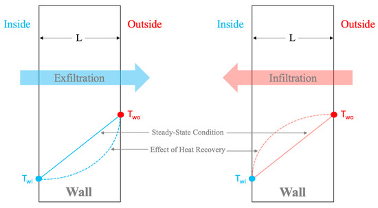
Figure 1.
Effect of airflow through the wall on the temperature profiles.
The initial step involved presenting the mathematical partial differential equation (PDE) model of the IHR phenomena and discussing the numerical method employed to solve this model. The IHR model took into consideration the thermal attributes of the wall, including the heat capacity and thermal conductivity, along with the effects of external and internal conditions. The numerical model of IHR was then verified against results derived from a steady-state analytical solution. A comprehensive analysis, including sensitivity analysis, was subsequently performed by running simulations of the model under broad design conditions, including different values of the wall’s heat capacity, thermal conductivity, airflow rate through the wall, direction of airflow, and wall porosity. Sensitivity analysis, by definition, is a technique used to determine how different values of an independent variable impact a particular dependent variable under a given set of assumptions. In the context of this study, sensitivity analysis was employed to determine the complex interactions between several key parameters and their collective influence on the infiltration heat recovery factor. Parameters such as heat capacity, Peclet number, wall porosity, and wall thickness were anticipated to significantly influence the IHR’s effectiveness. While each parameter has its distinct effect on the IHR factor, it is their collective and potentially non-linear interactions that offer insights into the behavior of the system. Specifically, variations in the wall thickness can significantly modulate the effects of other parameters. Consequently, a multi-variable sensitivity analysis was conducted to provide a comprehensive understanding of the combined impact of these variables on the IHR factor. This approach ensures a more robust grasp of the variables’ dynamics and contributes to a more accurate prediction of IHR behavior.
Though an explicit time-dependent analysis of infiltration heat recovery (IHR) behavior was not directly undertaken in this study, it is essential to highlight the inherent considerations incorporated into the analysis. Specifically, insights into the influence of time are provided by exploring delays in the temperature profiles, which are attributed to differences in wall heat capacities. In walls with a low heat capacity, an immediate heat transfer behavior is observed, resulting in a near-instantaneous response in temperature profiles. Conversely, a delayed response is noted in walls with a high heat capacity due to their inherent thermal energy storage capacity, leading to divergent temperature profiles over an elapsed period. This behavior emphasizes the time-dependent nuances of IHR. Moreover, the relationship between the IHR factor, heat capacity, and air velocity, as characterized by the Peclet number, further demonstrates the indirect effects of time on the heat recovery dynamics. Thus, while direct analysis may not have been undertaken, the influence of time on IHR was thoroughly addressed through these indirect examinations. The upcoming section describes the numerical modeling of the transient IHR model.
2.2. IHR Transient Model
The approach employed to model the infiltration heat recovery (IHR) phenomenon used a one-dimensional, single-layer wall model to represent the transient convection-diffusion system governed by energy conservation. As outlined in Equation (1) [7], conduction heat transfer exists through the wall due to the temperature difference between the indoor and outdoor environments, along with air leakage through the wall at a velocity denoted as Va, as illustrated in Figure 2. Additionally, uniform heat and mass flows were assumed in the one-dimensional model. The temperature, denoted as T in Equation (1), represents the temperature of both the air and the wall material at a given position (x) and time (t). In Equation (1), a positive value is assigned to the velocity Va when air flows in the direction of the x-axis, representing exfiltration or the movement of air from indoors to outdoors. Conversely, a negative value is given for Va when air flows from outdoors to indoors, which represents infiltration in this case. Furthermore, the term ρ⋅Cp expressed in Equation (1) signifies the wall’s and air’s heat capacity, reflecting the amount of heat storage per unit volume, where ρ represents the density and Cp represents the specific heat.
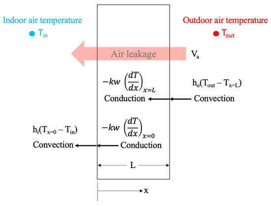
Figure 2.
Heat transfer at the boundaries of the wall.
The heat capacity of the wall and air, denoted as (ρ⋅Cp)wa in Equation (1), is expressed in Equation (2) [7], where ε is the wall porosity (%) characterizing the amount of air flowing through the wall:
The finite difference method was used as a numerical modeling approach to solve the IHR model, as represented by Equation (1). The discretized form of this equation is presented in Equation (3) as an approximate linear algebraic equation as follows:
The subscript i in Equation (3) represents the position x, and the superscript n denotes the time. Meanwhile, Δt and Δx represent the time step and wall thickness, respectively. Equation (3) is then rearranged and simplified, as shown in Equation (4), to be employed in a matrix form:
where the symbols φ and μ are defined as follows:
The boundary conditions for Equation (1) are defined in Equations (7) and (8), which represent the boundaries at x = 0 and x = L respectively. The right-hand side of Equations (7) and (8) depicts the discretized form of the boundary conditions. In these equations, hi and ho express the convection heat transfer coefficients of the interior and exterior films on the wall surfaces, respectively. Additionally, Twi represents the temperature of the interior surface of the wall, Tin is the indoor air temperature, Two is the temperature of the outdoor surface of the wall, and Tout is the outdoor air temperature.
For x = 0:
For x = L:
The numerical scheme presented above, which represents the interior nodes and the boundary nodes of the wall, was developed in Matlab, presented in a tridiagonal matrix, and solved using the L-U decomposition numerical approach. The finite difference method was chosen in this study for its efficiency and accuracy in handling the complex partial differential equation representing the relationship between advection and conduction heat transfer in the infiltration heat recovery phenomena. While numerous methods are available for solving such equations, the L-U decomposition was selected due to its efficient computational cost. To guarantee the accuracy of the numerical approach, verification analysis was performed by comparing the numerical results with the analytical solution of the IHR steady-state model. The numerical method results were found to align well with the analytical solutions, indicating its reliability for this problem, as presented in the next section.
2.3. IHR Steady-State Model
The analytical solution of the IHR steady-state model was utilized to verify the accuracy of the IHR numerical model. When assuming steady-state conditions for conduction and infiltration rates through the wall, where no energy storage is considered, the total thermal energy through the wall is defined in Equation (9) [3]:
The prospective influence of infiltration heat recovery can be represented as a function of a dimensionless term called the Peclet number. This number characterizes the connection between advection and conduction heat transfer within a body experiencing airflow. In the context of a building application, for instance, this relationship could be identified as the proportion between infiltration and conduction loss coefficients for the part of the wall where airflow is present. Furthermore, the impacts of heat recovery on the overall building load become negligible when the Peclet number is extremely small or exceptionally large. The only exception is when the amount of conduction heat transfer through the wall is minor. This leads to a situation where the infiltration heat recovery increases to its theoretical maximum of one. Accordingly, the analytical solution of the steady-state second-order differential equation presented in Equation (9) can be derived using both the Peclet number and Biot number [3], as shown in Equation (10) [3]:
where Bi is the Biot number and Pe is the Peclet number of the airflow and are estimated as follows [3]:
The value of the infiltration rate determines the Peclet value, where a Peclet value of zero means there is no infiltration, and a value of infinity indicates very high infiltration. Indeed, the Peclet number is considered negative when exfiltration occurs.
On the other hand, the film resistance of the wall’s surface will influence the air temperature just before it enters and immediately after it exits the wall. This is where the role of the Biot number becomes apparent. The Biot number, calculated for interior and exterior surfaces, reveals the convective characteristics of the wall surface, given that the conduction remains constant. The Biot number typically ranges from 1 to 10 in practical building scenarios. When the Biot number is zero for either surface, the wall surface film resistance becomes infinite, behaving like an adiabatic layer. Conversely, if the Biot number is infinitely large, the surface film heat transfer resistance becomes insignificant.
To verify the outcomes of the IHR numerical model, a comparison was performed with the analytical solution of the IHR steady-state model. The graph shown in Figure 3 presents a comparative analysis of the results from the two models across various Peclet number values. The numerical model was specifically configured for a wall with an extremely low heat capacity, while a constant thermal conductivity of 0.04 W/m⋅K was fixed for both models. The boundary conditions presumed an indoor air temperature of 20 °C and an outdoor air temperature of 40 °C. Further, the convection heat transfer coefficient was assumed to be 5 W/m2⋅K and 15 W/m2⋅K for the indoor and outdoor wall surfaces [24], respectively. As indicated in Figure 3, the outcomes of the numerical model align closely with the analytical solution. Therefore, it can be concluded that the developed IHR numerical model demonstrated notable accuracy and is suitable for further detailed analysis.
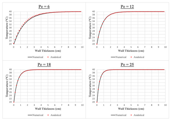
Figure 3.
Comparison between the IHR numerical model predictions and the analytical solution of the steady state IHR model for several Peclet number values.
2.4. Heat Recovery Factor
Certain research studies proposed the infiltration heat recovery factor (f) [7,15] to easily describe the impact of IHR. Theoretically, the IHR factor oscillates between zero and one. The maximum value of the IHR factor (f = 1) signifies instances where infiltration approaches zero. In contrast, at its minimum (f = 0), it signifies a situation where the mass flow rate of infiltration increases to such an extent that it surpasses the conduction heat transfer load, typically seen at very high Peclet numbers. To characterize the impact of IHR, the heat recovery factor (f) is calculated as follows [3]:
where Qrecov is the heat recovery rate, Qcond is the conduction heat transfer rate through the wall, and Qinf is the classical infiltration rate where no heat recovery is considered. The heat recovery rate can be expressed as follows [3]:
where is the mass flow rate of infiltration, Cp is the specific heat of air, Tin is the indoor air temperature, and Tout is the outdoor air temperature. It is worth noting that the second part on the right-hand side of Equation (13) represents the effective thermal load impact associated with infiltration. The infiltration rate that takes into account the heat recovery is estimated using Equations (15) and (16) [4]:
where Tsurf_in in Equation (16) is the wall’s indoor surface temperature. Therefore, based on the above equations, the heat recovery factor presented in Equation (13) can be modified as shown in Equation (17) [4]:
The overall effect of infiltration heat recovery becomes significant only when substantial heat transfer through the wall is present. As the IHR factor approaches unity, the infiltration load decreases significantly compared with the conduction load, yielding an almost negligible overall impact. While the IHR factor tends to decline at higher airflow rates, the absolute effect becomes more evident under higher loads. Theoretically, energy savings due to infiltration heat recovery can significantly increase until the loads of infiltration and conduction reach a similar magnitude. However, when infiltration predominantly governs the total heat transfer within a space, the influence of infiltration heat recovery diminishes until it once again becomes negligible.
3. Results and Discussion
The detailed analysis results of the temperature distribution within the wall are presented while examining various parameters and their impacts on the thermal behavior of the wall. The parameters of focus, which include heat capacity, direction of airflow rate, and airflow rate through the wall, were examined. Indeed, the wall’s temperature variations over time were influenced by the combined impact of air leakage and the wall’s thermal mass effect, with the wall’s heat capacity representing its capability to store thermal energy. The impact of the thermal energy storage of the wall on the infiltration heat recovery of the wall was the main subject of this study. Additionally, the analysis was conducted considering both high and low thermal conductivities, and the effect of wall porosity was also investigated. This investigation aimed to evaluate the thermal response of the wall under various conditions and gain insights into how these conditions altered the temperature distribution within the wall. The concept of infiltration heat recovery was also explored. The results obtained from this analysis are crucial for understanding the interactions and impacts of various factors on the thermal performance of walls, which could lead to potential impacts on energy consumption patterns.
3.1. Analysis of Temperature Distribution within the Wall
This section presents detailed results of the temperature profiles within the wall in response to varying several parameters, including the wall’s heat capacity, direction of airflow rate (i.e., infiltration or exfiltration), and various values of Peclet number (Pe). The analysis was performed for both high and low thermal conductivities of the wall with a wall thickness of 10 cm and a boundary condition of 20 °C for the indoor air temperature and 40 °C for the outdoor air temperature. The analyzed low thermal conductivity was assumed to be 0.04 W/m·K, while the high thermal conductivity implemented in the analysis was assumed to be 1.5 W/m·K. Note that the indoor and outdoor convection heat transfer coefficients of the indoor and outdoor wall surfaces were assumed to be 5 W/m2·K and 15 W/m2·K, respectively. Moreover, a wall porosity of 10% was assumed for all the analyses in this section. The results of the effect of wall porosity are given further in the next section of this paper.
3.1.1. Impact of HC on Temperature Profiles (No-Flow Case)
The effect of the heat capacity of the wall when no flow rate through the wall was considered (i.e., no infiltration or exfiltration) was explored. Sensitivity analysis was performed by running the numerical model with a wall heat capacity ranging between 250 and 3000 kJ/m3·K. In this analysis, a low thermal conductivity was considered. Figure 4 illustrates the temperature distribution within the wall for various heat capacities. As depicted in Figure 4, the higher the heat capacity of the wall, the higher the delay of thermal energy transfer due to the energy storage effect. On the other hand, the lower the heat capacity of the wall, the closer the temperature profile became to the steady-state condition where no energy storage effects were observed, and thus, there was no delay in thermal energy transfer. The objective of this analysis was to observe how the heat capacity of the wall affected the temperature distribution. By introducing airflow through the wall, the differentiation between the impact of infiltration heat recovery and its subsequent effect on the temperature profiles within the wall could be distinguished.
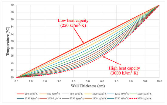
Figure 4.
Temperature profiles within the wall for various heat capacities for the no-flow case.
3.1.2. Impact of Airflow Rate on Temperature Profiles for High HC (Low-Thermal-Conductivity Case)
The effect of infiltration and exfiltration on the temperature distribution inside the wall was analyzed, specifically for a wall with high heat capacity and low thermal conductivity. In this case, the heat capacity of the wall was assumed to be 3000 kJ/m3·K and the wall porosity was 10%. To present the impact of the airflow within the wall, the Peclet number was varied from 32.4 to −32.4, where the negative sign represents the infiltration case (e.g., the direction of air leakage from outdoors to indoors). As illustrated in Figure 5, high flow rates significantly affected the temperature distribution within the wall. In the case of infiltration (the lines with the circle marks), higher thermal energy was absorbed with the increase in airflow rate due to the high outdoor temperature. When very high air velocity was induced (Peclet number equal to −32.4), most of the wall gained the thermal energy of the outdoor air and the temperature reached 40 °C in about 90% of the wall. In contrast, the temperature of the wall dropped gradually with the increase in the exfiltration rate (e.g., the direction of air leakage from indoors to outdoors) and equaled the indoor temperature for most of the wall when a very high Peclet number was induced. It is worth noting that the red line in Figure 5 represents the case of no airflow rate, where no infiltration or exfiltration was exerted, yet the curve demonstrated an exponential behavior due to the high thermal energy storage of the high heat capacity wall. Indeed, the impact of the infiltration heat recovery was obvious on the temperature distribution of the wall, especially with high infiltration rates. Accordingly, this effect on the wall’s temperature influenced the amount of heat gained through the wall, eventually affecting the cooling energy consumption.
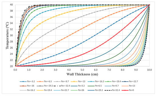
Figure 5.
Impact of airflow heat recovery on temperature profiles within the wall for various values of Peclet number representing infiltration and exfiltration for the high-heat-capacity case.
3.1.3. Impact of Airflow Rate on Temperature Profiles for Low HC (Low-Thermal-Conductivity Case)
A similar analysis was conducted to evaluate the impacts of infiltration and exfiltration with various values of Peclet number on the temperature profiles of a low-heat-capacity wall (250 kJ/m3·K). With a very low heat capacity of the wall, symmetrical curves were observed for infiltration and exfiltration. As depicted in Figure 6, when infiltration was explored, the wall tended to gain the high thermal energy of the outdoor air, especially with a high infiltration flow rate, which corresponded to a high Peclet number in Figure 6 (i.e., Peclet number equal to −32.4). On the other hand, thermal energy losses were observed when exfiltration was analyzed, where the wall approached the temperature of the indoor air. The red line in Figure 6 corresponds to the no-airflow case; thus, a linear steady-state temperature profile behavior was observed. This was due to the very low heat capacity of the wall considered in this analysis, where insignificant thermal energy storage was detected.
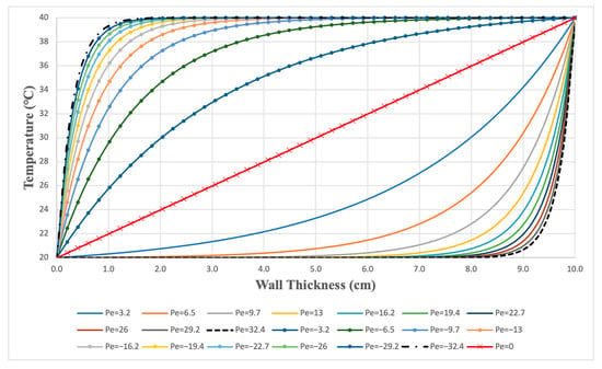
Figure 6.
Impact of airflow heat recovery on temperature profiles within the wall for various values of Peclet number representing infiltration and exfiltration for the low-heat-capacity case.
According to the temperature distributions presented in Figure 5 and Figure 6, which represent the high and low heat capacities of the wall, the high heat capacity wall was able to delay the effect of the infiltration heat recovery, thereby delaying the rise in temperature inside the wall. For instance, in the middle of the wall at a thickness of 5 cm, the temperature of the wall was 36.5 °C for a −3.2 Peclet number, while on the other hand, the temperature for the high heat capacity wall at the same position was only 27.8 °C for the same value of Peclet number. This difference in wall temperature illustrates the energy storage ability of the high heat capacity walls in delaying the impact of the infiltration heat recovery, thus, the effect on cooling energy consumption.
3.1.4. Difference in Temperature for High and Low HCs with High and Low Peclet Numbers (High-Thermal-Conductivity Case)
This analysis explored the temperature distribution behavior within the wall for the high- and low-heat-capacity walls for the high-thermal-conductivity case. High and low Peclet numbers were assessed for each heat capacity scenario. It is to be noted that the initial condition of the wall to solve the numerical model was 20 °C. As shown in Figure 7, the temperature of the low heat capacity wall responded faster to the surrounding conditions, especially when a high infiltration rate was considered. In this case, the results show a large difference in temperature between the high Peclet number (Pe = 9) and low Peclet number (Pe = 0.9) for the low-heat-capacity scenario. However, an insignificant difference in temperature was observed for the high heat capacity scenario when comparing the effects of high and low Peclet number cases. This analysis clearly demonstrated the significant influence of the wall’s heat capacity (i.e., the thermal mass of the wall) on the response of the wall’s temperature when high thermal conductivity was considered. Indeed, the effect of the infiltration rate (i.e., Peclet number) denoted the significance of infiltration heat recovery and how it could impact the temperature within the wall, and hence, the heat gained or lost through the wall.
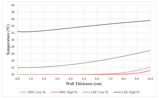
Figure 7.
Comparison of high- and low-heat-capacity scenarios for high and low Peclet numbers for high-thermal-conductivity wall.
3.2. Analysis of Infiltration Heat Recovery (IHR) Factor
To quantify the amount of infiltration heat recovery (IHR), the IHR factor (f) was evaluated. As mentioned in the Materials and Methods section (Section 2.4. Heat Recovery Factor), the maximum value that the IHR factor can achieve is one, and this occurs when the infiltration is significantly low. In addition, as more airflow passes through a wall, the contact between the air and the wall decreases, leading to a reduction in the IHR factor. When the infiltration reaches a significantly high mass flow rate (very high Peclet number), the IHR effect tends to approach zero. Therefore, it is clear that the infiltration rate through the wall directly affects the IHR factor; however, other factors could also influence the amount of heat recovery within the wall, such as the heat capacity and thermal conductivity of the wall. Accordingly, this section investigates in detail the IHR factor as a function of the Peclet number and the wall’s heat capacity, thermal conductivity, thickness, and porosity.
3.2.1. Impact of Pe on IHR Factor for High and Low HCs (Low-Thermal-Conductivity Case)
The results emphasized the correlation between low Peclet numbers and a high IHR factor across both high and low heat capacities. Specifically, when the Peclet number approached zero, the IHR factor almost reached one for both the high- and low-heat-capacity scenarios, as illustrated in Figure 8. When the Peclet number was increased, the IHR factor of the low- and high-heat-capacity walls started to deviate and reached a maximum deviation at Pe = 9.72. Beyond this point, the discrepancy in the IHR factor narrowed, with both the high- and low-heat-capacity walls converging to a similar IHR factor when the Peclet number was 32.4 or greater. The percentage difference in the IHR factor between the high and low heat capacities, corresponding to various Peclet numbers, is outlined in Table 1.
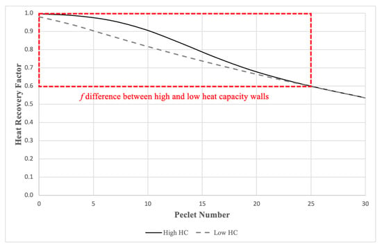
Figure 8.
The impact of Peclet number on the IHR factor for high and low heat capacities of the wall.

Table 1.
IHR factor difference between high- and low-heat-capacity walls for various values of Peclet number.
3.2.2. Impact of Heat Capacity on IHR Factor for a Range of Pe Values
A wide range of the wall’s heat capacity was analyzed ranging from 250 kJ/m3·K to 3000 kJ/m3·K to assess its impact on the IHR factor for both low- and high-thermal-conductivity walls. According to the results presented in Figure 9, walls with very low thermal conductivity (e.g., super-insulated walls with a value of about 0.04 W/m·K) significantly reduced the rate of conduction heat transfer, thus minimizing the overall heat recovery rate, which, in turn, increased the IHR factor. Indeed, increasing the infiltration rate also contributed to lowering the IHR factor, as indicated in Figure 9. However, it is to be noted that the impact of the heat capacity of the wall on the IHR factor became insignificant when very low-thermal-conductivity walls were considered. In fact, a moderate Peclet number of around 3 produced an IHR factor that ranged between 0.94 and 0.99, which represented the whole range of heat capacities. Even with high Pe values, such as 32, the minimum recorded IHR factor was about 0.56, which was fixed for the entire heat capacity range of the wall.
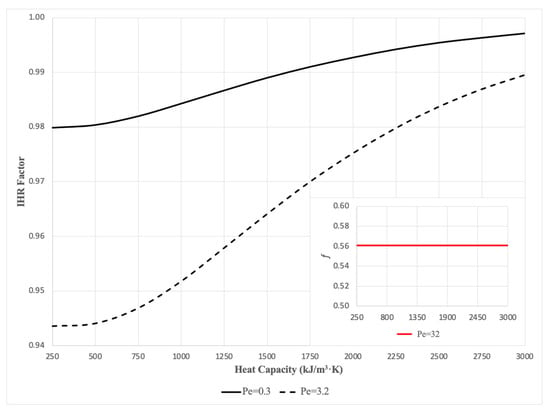
Figure 9.
Assessing the impact of a range of the wall’s heat capacity values on the IHR factor for a low-thermal-conductivity wall.
In contrast, the impact of the wall’s heat capacity on the IHR factor for high-thermal-conductivity walls was clearly evident, especially when the Peclet number was increased. As depicted in Figure 10, the larger the Peclet number, the greater the impact of the wall’s heat capacity on the IHR factor. For instance, if a Peclet number of 17 was considered, a low heat capacity of the wall delivered an IHR factor of around 0.09, while an IHR factor close to one was obtained when a very high heat capacity was considered.
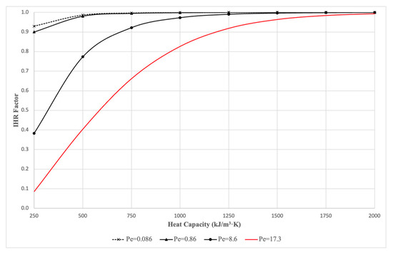
Figure 10.
Assessing the impact of a range of the wall’s heat capacity values on the IHR factor for a high-thermal-conductivity wall.
The interaction of some parameters, such as heat capacity, Peclet number, wall porosity, and wall thickness, was expected to play a crucial role in determining the effectiveness of the infiltration heat recovery. By conducting a sensitivity analysis, it was possible to provide a more robust understanding of how these variables interacted and influenced the IHR factor. While heat capacity, Peclet number, and wall porosity each had their impact on the IHR factor, their combined effect could lead to complex, non-linear responses that were not predictable from separate analyses. Furthermore, different wall thicknesses could alter these effects significantly, providing a more comprehensive understanding of the infiltration heat recovery behavior. Therefore, this type of multi-variable sensitivity analysis helped to deliver a broader and more accurate understanding of the effect of these parameters on the performance of the IHR factor of the wall. The following sections present the combined effect of heat capacity, Peclet number, wall thickness, and wall porosity on the IHR factor.
3.2.3. Combined Effect of HC and Pe on IHR Factor for Several Wall Thicknesses
A sensitivity analysis was performed to explore how the IHR factor was sensitive to the combined effect of infiltration rate (represented by the Peclet number), the heat capacity of the wall, and the wall thickness. The heat capacity of the wall was varied from 250 to 2000 kJ/m3·K. In this analysis, the thermal conductivity of the wall was assumed to be 1.5 W/m·K for a reasonable conventional construction wall system. The wall porosity was fixed at 10% in this specific analysis and was varied in the following sensitivity analysis. As depicted in Figure 11, the IHR factor generally increased as the wall thickness increased. For example, for a heat capacity of 400 and a Peclet number of 10, the IHR factor increased from 0.57 (for the 10 cm wall) to 0.96 (for the 40 cm wall). This suggests that thicker walls improve infiltration heat recovery, likely due to enhanced heat retention capability. Moreover, as the Peclet number increased, the IHR factor tended to decrease. This implies that when the rate of airflow (or advective transport) becomes more significant compared with that of heat diffusion, heat recovery reduces. This trend was consistently observed across all wall thicknesses and heat capacities. It is also worth noting that the influence of the airflow rate on the IHR factor lowered with thicker walls, thus enhancing the heat recovery potential. Similarly, as the heat capacity of the wall increased, the IHR factor increased for a fixed Peclet number, indicating that construction wall systems with higher heat capacities can store and recover more heat. For instance, at a Peclet number of 10 and a wall thickness of 10 cm, the IHR factor increased from 0.36 (for a heat capacity of 250) to almost 1 (for a heat capacity of 2000). However, the impact of the heat capacity on the IHR factor became lower for larger wall thicknesses. In summary, a higher IHR factor, implying better heat recovery, was generally associated with thicker walls, lower Peclet numbers, and higher heat capacities. It is important to note that the specific values and trends might differ in real-world applications due to other factors not being considered in this analysis.
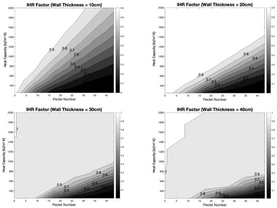
Figure 11.
Sensitivity analysis for the combined effect of Peclet number, heat capacity, and wall thickness on the IHR factor.
The above analysis presented in Figure 11 represents the 10% wall porosity case results. However, it is important to note that the wall porosity could significantly influence the effectiveness of infiltration heat recovery, primarily due to the variability of the airflow rate through the wall. Therefore, the wall porosity was incorporated into the following sensitivity analysis to thoroughly examine its combined effect on the IHR factor, along with other parameters.
3.2.4. Combined Effect of HC and Wall Porosity of IHR Factor for Several Pe Values
The results of the analysis shown in Figure 12 suggest that as the Peclet number increased from 0.9 to 26, the IHR factor generally decreased. This indicates that as the Peclet number increases (denoting that advective transport is becoming more significant relative to diffusive transport), the IHR factor decreases, showing a lower level of heat recovery. For instance, with a heat capacity of 400 and a wall porosity of 10%, the IHR factor was approximately 0.93 when the Peclet number was 0.9. However, if the Peclet number was increased to 9 under the same conditions, the IHR factor dropped to about 0.65. If an even higher Peclet number was considered, such as 26, under the same conditions, the IHR factor further decreased to 0.15.
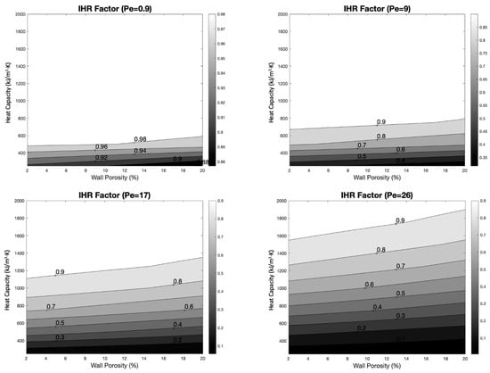
Figure 12.
Sensitivity analysis for the combined effect of the wall porosity, heat capacity, and Peclet number on the IHR factor.
On the other hand, within each set of Peclet numbers, there appeared to be a pattern where the IHR factor generally decreased as the wall porosity increased from 2% to 20%. This suggests that a more porous wall leads to lower IHR, possibly due to increased heat loss through the porous material. However, the influence of wall porosity appeared to be insignificant, especially for low Peclet numbers compared with the other factors. It is worth noting that the trend of the IHR factor as a response to wall porosity was not perfectly linear, and in some cases, the IHR factor could increase with an increase in the wall porosity, indicating more complex underlying interactions. Moreover, as stated earlier in this study, the wall’s heat capacity significantly affected the IHR factor. Therefore, as the heat capacity increased, the influence of wall porosity on the IHR factor also increased, as illustrated by the results in Figure 12. Furthermore, the combined effect of both heat capacity and wall porosity on the IHR factor could be significant. A careful analysis of the results revealed that at the lowest heat capacity and wall porosity (250 kJ/m3·K and 2%, respectively), the IHR factor was approximately 0.025, whereas, at the highest heat capacity and wall porosity (2000 kJ/m3·K and 20%, respectively), it increased to around 0.923, which was a difference of about 97% in heat recovery.
Infiltration heat recovery is a critical aspect that can directly impact the cooling energy consumption of a building, even though currently it has been ignored by existing energy simulation tools. By incorporating IHR into the energy simulation models, the discrepancies between the simulated and actual energy consumption can be reduced, leading to more accurate predictions and efficient energy management strategies. Moreover, as discussed previously, this study thoroughly analyzed the significance of a list of parameters in predicting the performance of IHR, such as the heat capacity of the wall, thermal conductivity of the wall, thickness of the wall, infiltration flow rate, direction of airflow through the wall, and the wall’s porosity. Specifically, the study explained the interrelationships between these parameters and their combined influence on IHR, which is not discussed in the current literature. By highlighting the interaction between the stated parameters, this study contributes to further understanding the behavior of IHR in walls and its impact on the overall thermal behavior of a building. In addition, this study contributes to refining energy simulation tools, allowing them to capture more details of the building’s thermal behavior. The insights gathered from this study also contribute to the wider knowledge base in energy-efficient building design. Understanding the dynamics of IHR, wall heat capacity, and other factors could influence architectural and construction practices, creating more energy-efficient and sustainable structures.
While this study provides significant insights into infiltration heat recovery and its influence on the cooling energy consumption of buildings, there are some potential limitations:
- This research was based on a defined set of parameters, such as wall heat capacity, wall thermal conductivity, Peclet number, and wall porosity, which means that the findings might not generalize to other conditions or parameters not included in the study.
- While this study offers valuable data on the IHR factor for various wall thicknesses and heat capacities, the real-world application could be affected by numerous other variables, such as climate conditions and variations in building materials, which are not considered in this study.
- The applicability of these findings to different types of buildings, such as residential or commercial, high rise or single story, could vary; therefore, more diverse studies are required for a better understanding of this specific topic.
- Future studies on infiltration heat recovery (IHR) should also consider the implications of “seeming air tightness” in building partitions. Even when structures pass standard tests, they can still have unexpected heat demands due to phenomena like wind washing, particularly in walls insulated with fibrous materials [25]. For instance, research has shown substantial reductions in thermal resistance, up to 85%, because of wind washing in walls insulated with loose mineral wool [26]. Exploring these interactions can further refine our understanding of IHR in real-world scenarios.
Finally, infiltration heat recovery has not been adequately incorporated into building energy simulation tools to date. Thus, it is crucial to precisely integrate IHR modeling into building energy simulation tools to thoroughly investigate the effect of IHR on the cooling energy consumption of buildings.
4. Conclusions
This study addressed the lack of analysis on the transient behavior of the convection-diffusion model for infiltration heat recovery (IHR) and the impact of the wall’s heat capacity, along with other factors. Understanding this relationship is crucial for accurate predictions of the energy performance of buildings. Therefore, the findings of this research study aimed to provide valuable insights into the performance of IHR and the impact of several factors, including the wall’s heat capacity, thermal conductivity, airflow rate across the wall, airflow direction, and wall porosity, in influencing the temperature distribution and heat recovery factor within the wall.
The results of this study indicated that the heat capacity of the wall plays a crucial role in delaying the temperature rise within the wall, with higher heat capacity walls exhibiting a greater delay. Conversely, walls with very low thermal conductivity, such as super-insulated walls, minimize the rate of conduction heat transfer, reducing the overall heat recovery rate and increasing the IHR factor. The impact of the wall’s heat capacity on the IHR factor became insignificant when very low thermal conductivity walls were considered. However, heat capacity’s influence became more evident for high thermal conductivity walls, especially as the Peclet number increased. The sensitivity analysis revealed that the IHR factor generally increased as the wall thickness increased, with thicker walls providing enhanced heat retention and better heat recovery potential. Additionally, the influence of the airflow rate on the IHR factor diminished with thicker walls, further enhancing the heat recovery. A higher IHR factor was generally associated with thicker walls, lower Peclet numbers, and higher heat capacities. Wall porosity also played a role in determining the effectiveness of infiltration heat recovery, with more porous walls experiencing increased heat loss through the material, resulting in lower IHR factors. However, the influence of wall porosity appeared to be less significant, particularly for low Peclet numbers, compared with other factors. These findings highlight the importance of considering heat capacity, thermal conductivity, wall thickness, and wall porosity in understanding the performance of the infiltration heat recovery. Incorporating these insights into energy-efficient building design and energy simulation models can lead to more accurate predictions, enhanced energy management strategies, and reduced cooling energy consumption.
By considering the transient behavior of IHR and the thermal energy storage of walls, designers can optimize energy consumption patterns and enhance the performance of buildings. Future research in this area could further explore additional factors and optimize building design to maximize the benefits of infiltration heat recovery. In addition, beyond the immediate focus of infiltration heat recovery, future research should also consider the broader implications of uncontrolled airflow in buildings. This includes drafts, pollutant transport, moisture challenges, and potential mold growth. Addressing these concerns will offer a more comprehensive perspective on building performance, merging energy efficiency with occupant well-being. Finally, this study contributes to the field of building physics by providing a detailed understanding of the interactions between IHR, thermal mass, and other influential factors, in addition to enhancing the accuracy of building energy modeling and prediction of building energy performance.
Funding
This research received no external funding.
Data Availability Statement
Data is available upon request.
Conflicts of Interest
The authors declare no conflict of interest.
Nomenclature
| Symbols | Subscripts | ||||
| L | Wall thickness (m) | ε | Wall porosity (%) | in | Indoor air |
| T | Temperature (°C) | Δx | Step of wall thickness (m) | out | Outdoor air |
| ρ | Density (kg/m3) | Δt | Step of time (s) | wi | Indoor wall surface |
| Cp | Specific heat | Bi | Biot number (-) | wo | Outdoor wall surface |
| t | Time (s) | Pe | Peclet number (-) | w | Wall |
| V | Air velocity (m/s) | m∙ | Mass flow rate (kg/s) | a | Air |
| k | Thermal conductivity (W/m·K) | U | U value of the wall (W/m2°C) | i | Position |
| x | Space coordinate (m) | Q | Thermal load (W) | n | Time step |
| h | Convection heat transfer coefficient (W/m2·K) | f | Infiltration heat recovery factor (-) | J | Number of last discretization node |
References
- ASHRAE Committee. ASHRAE Handbook: Fundamentals; ASHRAE Committee: Atlanta, GA, USA, 2009. [Google Scholar]
- Sherman, M.H.; Walker, I.S. Heat Recovery in Building Envelopes, Energy Performance of Buildings Group Indoor Environment; Project# LBNL 53484; Department Lawrence Berkeley National Laboratory: Berkeley, CA, USA, 2003. [Google Scholar]
- Solupe, M.; Krarti, M. Assessment of infiltration heat recovery and its impact on energy consumption for residential buildings. Energy Convers. Manag. 2014, 78, 316–323. [Google Scholar] [CrossRef]
- Solupe, M. Assessment of Steady State Infiltration Heat Recovery Models and Their Impact on Predicted Home Energy Consumption. Master’s Thesis, Department of Civil, Environmental, and Architectural Engineering, University of Colorado, Boulder, CO, USA, 2011. [Google Scholar]
- Anderlind, G. Energy consumption due to air infiltration. In Proceedings of the 3rd ASHRAE/DOE/BTECC Conference on Thermal Performance of the Exterior Envelope of Buildings, Clearwater Beach, FL, USA, 2–5 December 1985; pp. 201–208. [Google Scholar]
- Liu, M. Study of Air Infiltration Energy Consumption; Texas A&M University: College Station, TX, USA, 1992. [Google Scholar]
- Krarti, M. Effect of Air Flow on Heat Transfer in Walls. Sol. Energy Eng. 1994, 116, 35–42. [Google Scholar] [CrossRef]
- Buchanan, C.; Sherman, M. A Mathematical Model for Infiltration Heat Recovery; Lawrence Berkeley National Laboratory: Berkeley, CA, USA, 2000. [Google Scholar]
- Abadie, M.; Finlayson, E.; Gadgil, A. Infiltration Heat Recovery in Building Walls: Computational Fluid Dynamics Investigations Results; LBNL-51324; Technical Report; Lawrence Berkeley National Laboratory: Berkeley, CA, USA, 2002. [Google Scholar]
- Qiu, K.; Haghighat, F. Modeling the combined conduction-air infiltration through diffusive building envelope. Energy Build. 2007, 39, 1140–1150. [Google Scholar] [CrossRef]
- Tallet, A.; Liberge, E.; Inard, C. Fast POD method to evaluate infiltration heat recovery in building walls. Build. Simul. 2017, 10, 111–121. [Google Scholar] [CrossRef]
- Bhattacharyya, S.; Claridge, D. The energy impact of infiltration through insulated walls. J. Sol. Energy Eng. Trans. ASME 1995, 112, 132–139. [Google Scholar]
- Janssens, A. Methodology for measuring infiltration heat recovery for concentrated air leakage. In Research in Building Physics; CRC Press: Boca Raton, FL, USA, 2003; pp. 759–764. [Google Scholar] [CrossRef]
- Ackerman, M.; Bailey, R.; Dale, D.; Wilson, D. Infiltration Heat Recovery–ASHRAE Research Project 1169–Final Report; University of Alberta, Department of Mechanical Engineering: Edmonton, AB, Canada, 2004. [Google Scholar]
- Brownell, C.J. Measurement of infiltration heat recovery in a test cell with high flow rates. J. Build. Phys. 2015, 38, 350–359. [Google Scholar] [CrossRef]
- Alongi, A.; Angelotti, A.; Mazzarella, L. Experimental investigation of the steady state behaviour of Breathing Walls by means of a novel laboratory apparatus. Build. Environ. 2017, 123, 415–426. [Google Scholar] [CrossRef][Green Version]
- Wong, J.M.; Glasser, F.P.; Imbabi, M.S. Evaluation of thermal conductivity in air permeable concrete for dynamic breathing wall construction. Cem. Concr. Compos. 2007, 29, 647–655. [Google Scholar] [CrossRef]
- Fawaier, M.; Bokor, B. Dynamic insulation systems of building envelopes: A review. Energy Build. 2022, 270, 112268. [Google Scholar] [CrossRef]
- Zhang, C.; Wang, J. Determining the critical insulation thickness of breathing wall: Analytical model, key parameters, and design. Case Stud. Therm. Eng. 2021, 27, 101326. [Google Scholar] [CrossRef]
- Alongi, A.; Angelotti, A.; Mazzarella, L. Experimental validation of a steady periodic analytical model for Breathing Walls. Build. Environ. 2020, 168, 106509. [Google Scholar] [CrossRef]
- Zhang, C.; Xiao, F.; Wang, J. Design optimization of multi-functional building envelope for thermal insulation and exhaust air heat recovery in different climates. J. Build. Eng. 2021, 43, 103151. [Google Scholar] [CrossRef]
- Alongi, A.; Angelotti, A.; Mazzarella, L. A numerical model to simulate the dynamic performance of Breathing Walls. J. Build. Perform. Simul. 2021, 14, 155–180. [Google Scholar] [CrossRef]
- Alongi, A.; Angelotti, A.; Mazzarella, L. Investigating the control strategies for Breathing Walls during summer: A dynamic simulation study. In Proceedings of the 17th IBPSA Conference, Bruges, Belgium, 1–3 September 2021; pp. 261–268. [Google Scholar]
- ASHRAE_Committee ASHRAE Standard 140-2017; Standard Method of Test for the Evaluation of Building Energy Analysis Computer Programs 2020. American Society of Heating, Refrigerating and Air-Conditioning Engineers, Inc.: Atlanta, GA, USA, 2020.
- Wójcik, R.; Kosinski, P. Seeming air tightness of construction partitions. Energy Procedia 2015, 78, 1519–1524. [Google Scholar] [CrossRef]
- Kosiński, P.; Wójcik, R.; Semen, B. Experimental study on the deterioration of thermal insulation performance due to wind washing of the cavity insulation in leaky walls. Sci. Technol. Built Environ. 2019, 25, 1164–1177. [Google Scholar] [CrossRef]
Disclaimer/Publisher’s Note: The statements, opinions and data contained in all publications are solely those of the individual author(s) and contributor(s) and not of MDPI and/or the editor(s). MDPI and/or the editor(s) disclaim responsibility for any injury to people or property resulting from any ideas, methods, instructions or products referred to in the content. |
© 2023 by the author. Licensee MDPI, Basel, Switzerland. This article is an open access article distributed under the terms and conditions of the Creative Commons Attribution (CC BY) license (https://creativecommons.org/licenses/by/4.0/).