Abstract
The stability of the casing is a crucial prerequisite for implementing the in situ high-temperature steam injection method in oil shale reservoirs. In order to address the issues of substantial expansion, concentrated thermal stresses, and susceptibility to damage observed in traditional straight casings under high temperatures, this paper proposes the utilization of a corrugated casing structure. In this regard, to investigate the impact of the shape and structure of the wellbore casing on its mechanical properties, identical corrugated and straight casings were selected and studied. Uniaxial compression and tensile tests were conducted on the casings, along with coordination deformation experiments between the casing and cement sheath under varying temperatures. Numerical simulations were employed to obtain the deformation characteristics of the corrugated and straight casings under axial compression and tension loads, as well as the stress distribution on the outer casing wall. The results showed that when subjected to the same amount of deformation under axial loading, the corrugated casing experienced lower compressive and tensile loads compared to the straight casing. Moreover, under the sole constraint of cement sheath, increasing the temperature led to lower vertical strains (perpendicular to the ground) at all measuring points of the corrugated casing as compared to the corresponding strains in the straight casing. Numerical simulations revealed that, under the same temperatures, the deformation at the interface between the corrugated casing and the cement sheath was smaller, while the vertical stress at the interface of the corrugated casing was also lower than the straight casing. Overall, the corrugated casing, with its corrugated structure that enabled micro-deformation, effectively mitigated the axial deformation of the casing caused by thermal expansion. Consequently, the corrugated casing reduced the extrusion of wellbore casing on the cement sheath, thereby preserving the integrity and stability of the wellbore cementing structure.
1. Introduction
The world is still reliant on fossil fuels, which continue to experience significant global demand [,,,,]. As an unconventional hydrocarbon resource capable of bridging the gap in the supply for conventional fossil fuels, oil shale has garnered increasing attention from researchers due to its abundant reserves and development feasibility [,,,,]. In situ oil shale extraction techniques offer an environment-friendly and highly productive method to develop oil shale. Based upon methods such as electrical, convection, and radiation heating, the in situ extraction involves injecting heat into the oil shale formation, causing thermal decomposition of organic matter into shale oil and hydrocarbon gases [,,,,]. The research team at Taiyuan University of Technology, China, has developed an in situ steam-injection technology for extracting oil shale and has conducted extensive theoretical and experimental studies for the past few years [,]. In the process of in situ steam injection for extracting oil shale, super-heated steam within the temperature range of 550–600 °C needs to be injected into the oil shale formation [,]. Therefore, the wellbore structure must meet the requirements for effective operation in high-temperature and high-pressure environments. Traditional wellbore casings are mostly straight and may experience thermal expansion due to high temperatures, leading to inconsistent deformations between the casing and the cement sheath. This can compromise the integrity and gas-tightness of the interface, resulting in gas migration and fluid leakage, thereby affecting the safety of the production process [,]. Therefore, it is crucial to address the issue of excessive casing deformation during high-temperature steam injection.
Currently, research on wellbore casings mainly focuses on areas such as heavy oil-thermal recovery and the development of shale oil, with numerous scholars studying the stability of casings during thermal injection processes. Zhao Xinbo et al. [] reported an analytical solution for stress distribution in a multilayer system consisting of casing-cement sheath formation under thermal-structural coupling and discussed the influence of the thickness of cement sheath, its elastic modulus, Poisson’s ratio, its formation temperature, and the number of casing-cement sheath layers on the distribution of Mises stress on the inner wall of the innermost casing. Based upon the elastoplastic mechanics theory, Lian Zhanghua [] and Feng Jin [] established symmetrical finite element models of formation-missing cement sheath casing and suggested that the absence of cement sheath could increase the internal casing stresses and even lead to casing failure. Jiang Ke et al. [] studied the effects of cement-sheath channeling, casing eccentricity, and changes in the wellbore diameter on the casing damage under poor cementing quality. Their results showed that the absence of cement sheath led to severe stress concentration on the inner wall of the casing, whereas the casing stresses increased with the angle of absence, while casing deviation from the axis significantly increased the casing stresses. Liu Kui et al. [] proposed that the geometric dimensions of wellbore casings played a significant role in maintaining the integrity of wellbore, and that appropriately increasing the casing thickness and reducing the outer casing diameter could help reduce the damage to casing. Xi Yan et al. [] established a full-scale pre-stressed cementing model and suggested that applying pre-stress to wellbore casings during the cementing phase could help maintain the sealing of the cement sheath.
Numerous researchers have extensively studied the factors affecting the casing stresses. However, there is limited research on the relationship between the shape and structure of casing and the casing stresses. In the context of in situ high-temperature steam extraction of oil shale, where injecting steam with the temperature range of 550–600 °C into the formation is necessary, the demands on the casings are even higher. Taiyuan University of Technology (China) has proposed the use of corrugated casings to mitigate thermal stresses and deformations that occur at high temperatures, thus maintaining the stability of the structure of casing-cement sheath. Therefore, conducting research on the deformation characteristics of corrugated and straight casings under axial stress and high-temperature environments is of paramount importance for understanding the mechanical properties of casings and improving the stability of wellbores.
This study initially investigates the characteristics of overall deformation and local strain of casing under uniaxial loads at room temperature. Based upon a custom-made experimental system for the coordinated deformation of casing-cement sheath, the strain variations at different measurement points of corrugated and straight casings are obtained under conditions of no axial load and with cement sheath constraint. Additionally, numerical simulations are conducted to determine the coordinated deformation characteristics of the two casing-cement sheath configurations under high-temperature environments. It provides an important reference for improving the mechanical properties of the wellbore casing and enhancing the stability of the hot-recovery wellbore.
2. Experimental Section
2.1. Uniaxial Compression and Uniaxial Tensile Tests
2.1.1. Experimental System and Samples
The uniaxial compression test was conducted using the HCT306E testing machine (Figure 1a), while the uniaxial tensile test was performed using the HUT106A testing machine (Figure 1b). The strain measurement system employed in the experiments consisted of the TST3826F static strain collection system and an associated computer (Figure 1c).
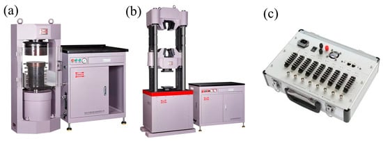
Figure 1.
Experimental equipment: (a) Uniaxial compression testing machine; (b) Uniaxial tensile testing machine; (c) Static strain collection system.
The corrugated and straight casings used in the experiments were composed of Q235 steel, with a length of 300 mm, inner diameter of 90 mm, and the wall thickness of 3 mm. Three measurement points, labeled as 1#, 2#, and 3#, were placed at the distances of 75 mm, 150 mm, and 225 mm from the upper-end face of the casing, respectively. In the uniaxial compression test, bi-directional strain gauges were affixed at the crests and troughs of each measurement point on the casing samples. For the uniaxial tensile test, solid round bars were welded to both the ends of the casing samples to allow them to be securely fixed to the grips of the tensile testing machine, as shown in Figure 2.
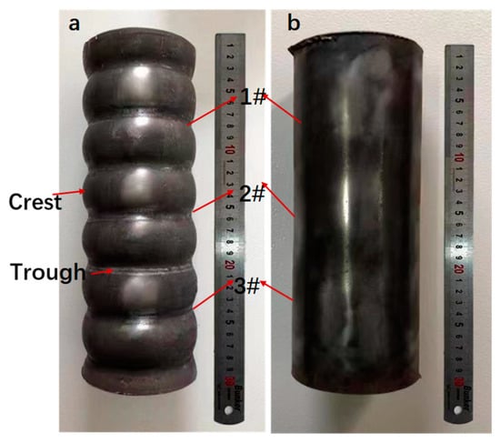
Figure 2.
Compression and tensile test samples: (a) Corrugated casing; (b) Straight casing.
2.1.2. Metal Casing Compression Experimental Procedure
- The casing was placed in the loading chamber, ensuring sufficient contact with the base of the testing machine and the spherical seat to prevent stress concentration due to uneven end faces.
- The leads of the strain gauges to the strain measurement system were connected, and the parameters were adjusted accordingly.
- The testing machine was turned on, and axial compressive stress was applied on the casing at a certain loading rate (2 mm/min) until it exceeded the compressive strength and local plastic deformation occurred. The specimen was unloaded, and the testing machine was turned off. Complies with metal compression standards: GB/T7314-2005 [].
2.1.3. Metal Casing Uniaxial Tensile Test Procedure
- The arrangement of strain gauges for the casing used in the uniaxial tensile test followed the same procedure as the uniaxial compression test.
- The two ends of the casing were positioned at the upper and lower grips of the tensile testing machine. The clamping force of the grips was adjusted. The wiring connections were inspected, and the parameters were configured accordingly.
- The testing machine was activated, and tensile stress was gradually applied at a certain loading rate (2 mm/min) until it exceeded the casing’s tensile strength and localized fracture occurred. The specimen was unloaded, and the testing machine was switched off. Complies with metal stretching standards: GB/T 228.1-2010 [].
2.2. Collaborative Deformation Experiment of Casing Cement Sheath under High Temperature
Figure 3a shows the schematic of the experimental setup used for the thermal expansion of the casing with a cement-sheath constraint. The following are the experimental samples and process:

Figure 3.
Casing thermal-expansion experiments. Results: (a) Casing thermal-expansion experiment site; (b) Schematic of the casing thermal-expansion experimental setup; (c) Schematic of the leakage detection pipe’s outlet. 1. Heating rod; 2. Insulation cotton; 3. Corrugated casing; 4. Cement sheath; 5. Outer shell; 6. Temperature controller; 7. Strain gauge box; 8. Computer; 9. Thermocouple; 10. Strain gauge; 11. Leakage testing interface; 12. Pressure gauge; 13. Valve; 14. Air pump; 15. Switch.
- First, the strain gauges were installed on the outer surface of the casing at the designated measurement points. They were connected to the strain measurement system using appropriate wiring.
- The CA50 aluminate cement slurry was injected into the space between the casing and the external restraining steel shell. During the process, the assembly was constantly shaken. The corresponding thermocouples and leakage detection pipes were embedded at their respective locations during the grouting process.
- Standard concrete curing procedures were followed to cure the specimens for a minimum of 28 days until they reached the desired final strength.
- The heating rod was suspended at the axial position of the casing. The top was covered with insulating tiles, and the pipelines of the temperature control/testing system, strain measurement system, and leakage detection system were sequentially connected and inspected. Appropriate contact between the outlet of the leakage detection pipe and the outer surface of the metal casing was ensured, as shown in Figure 3c.
- The heating rod was turned on, and its power was adjusted to raise the temperature to the predetermined value within one hour. After reaching the temperature threshold, the temperature was maintained for one hour to ensure thorough heating of the entire experimental setup. Once the strain and temperature values stabilized, high-pressure gas was slowly introduced into the experimental setup using an air pump. The pressure was set at 0.2 MPa. If the pressure reading on the gauge did not drop, it indicated good air tightness at the casing-cement-sheath interface, further confirming the absence of damage to the interface. Conversely speaking, a decrease in pressure indicated damage at the casing-cement-sheath interface.
- Step 5 was repeated to sequentially increase the temperature of experimental setup to 80 °C, 100 °C, and 120 °C. The experiment was stopped upon the failure of the casing-cement-sheath interface in the corrugated casing.
3. Experimental Results
3.1. Uniaxial Compression and Tensile Test Results
Figure 4a,b show the load-displacement curves for the uniaxial compression and uniaxial tension tests of the casing, respectively. From Figure 4a, it can be observed that, with the increase in deformation, the compressive load on both the corrugated casing and the straight casing increased. For the same deformation, the compressive load on the corrugated casing was significantly smaller than that on the straight casing. From Figure 4b, it can be observed that the corrugated casing bore a lower tensile load than the straight casing for the same deformation. Overall, in both the uniaxial compression and uniaxial tension tests, when the corrugated casing and the straight casing underwent the same axial deformation, the corrugated casing exhibited a significantly lower axial load than the straight casing. Additionally, both types of casing demonstrated a higher resistance to compression than to tension.
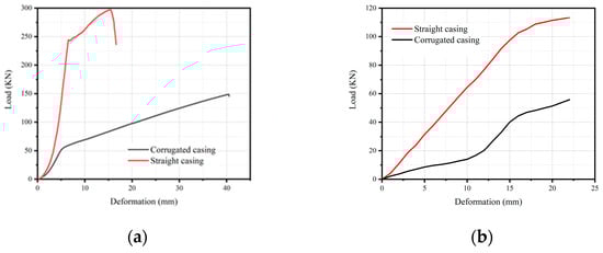
Figure 4.
Relationship between load variation of casing and deformation: (a) Compression experiment; (b) Tensile experiment.
Figure 5 shows the comparison between the deformation of straight casing and corrugated casing after the uniaxial compression and uniaxial tension tests. From Figure 5a, it can be observed that the straight casing exhibited irregular twisting plastic deformation under compression, while the corrugated casing experienced significant radial expansion at a specific wave crest, with less noticeable deformation in the remaining corrugated regions. From Figure 5b, it is evident that both the corrugated casing and straight casing underwent diameter contraction during the tension process. The diameter contraction was more pronounced near the midpoint of the casing, where both types of casings exhibited fracture damage. The length and width of the fracture cracks in the corrugated casing were smaller than those in the straight casing, as indicated by the red arrows.
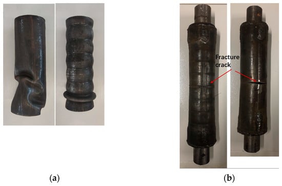
Figure 5.
Compression and tensile deformation effects of the two types of metal casings, (a) Compression casing (b) Tensile casing.
Figure 6 shows the vertical strain–time curves of the peak and trough values at various measurement points on the corrugated casing. Figure 6a–c represent the curves of the vertical strain (red line) at the peak and the vertical strain (blue line) at the trough for Measurement Points #1, #2, and #3 on the corrugated casing, respectively. The results show that the vertical strain at the peak was positive, indicating tensile strain, while the vertical strain at the trough was negative, indicating compressive strain. It can be inferred that, when the corrugated casing was subjected to overall compressive loading, the peak regions at various measurement points exhibited tensile strain, while the trough regions exhibited compressive strain. The local deformation trend of the corrugated casing’s individual structures did not entirely align with the overall deformation trend.
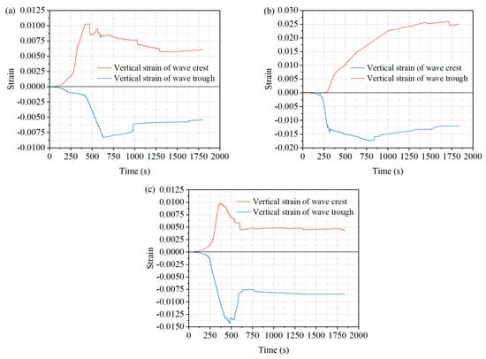
Figure 6.
Vertical strain–time curve of crests and troughs at each measurement point: (a) Point #1, (b) Point #2, (c) Point #3.
3.2. Experimental Results of Cement Sheath–Casings’ Synergistic Deformation under High Temperature
The comparative study of the synergistic deformation between the casing and the cement sheath under different temperatures, with the presence of a consolidated cement sheath, was used to study the deformation characteristics of the corrugated and straight casings. The experimental results are shown in Figure 7. The results showed that, under the same temperature conditions, the horizontal strain at each measurement point of the corrugated casing was always greater than the vertical strain, while the vertical strain of the straight casing was always greater than the horizontal strain. The vertical strain of the straight casing is nearly twice that of the corrugated casing. Moreover, for the same temperature conditions, the vertical strain of the corrugated casing was always smaller than that of the straight casing. As the temperature increased, both the horizontal and vertical strains at the measurement points of the corrugated and straight casings increased, indicating thermal expansion for both types of casings. When the temperature reached 120 °C, the bonding force provided by the cement sheath surrounding the straight casing was insufficient to prevent axial expansion deformation, leading to a significant increase in the vertical strain of the straight casing. Meanwhile, the pressure reading in the leakage detection system connected to the straight casing-cement-sheath thermal expansion test device gradually decreased, indicating gas leakage and the failure of the seal at the straight casing-cement sheath interface. However, the magnitudes of the horizontal and vertical strains of the corrugated casing exhibited only slight increases, and the pressure reading in the connected system showed no significant change.

Figure 7.
Variation in strain at each measuring point of the corrugated casing over time. (a) Strain-versus-time curve under 60 °C conditions; (b) Strain-versus-time curve under 80 °C conditions; (c) Strain-versus-time curve under 100 °C conditions; and (d) Strain-versus-time curve under 120 °C conditions.
This result was attributed to the absence of axial constraint load in the experimental setup as well as the circumferential constraint provided by the solidified cement sheath. Consequently, the horizontal strain of the straight casing was always smaller than the vertical strain. In contrast, the corrugated structure of the casing allowed it to form an interlocking interface with the solidified cement sheath, which effectively enhanced the cement sheath’s ability to secure the casing and prevent axial expansion deformation. Therefore, the vertical strain of the corrugated casing was consistently smaller than the horizontal strain, and with the increase in temperature, the growth rate of strain values remained relatively small.
4. Numerical Analysis
Casing damage remains a challenging issue that significantly affects the stability of wellbores with heat recovery. Scholars have conducted extensive research both domestically and internationally, employing methods such as numerical simulations to analyze the casing stress and factors affecting it. Wang Meng [] investigated the effects of pre-stress, thermal expansion coefficient, and elastic modulus on the stress distribution on the surface of different heat transfer media under high-temperature environments using the finite element method. Gao Lijun [] developed a shear finite element model for wellbore casings and concluded that establishing the wellbore away from the slip plane effectively reduces the casing shear damage caused by the formation slippage. However, the sole modification of the cement’s mechanical properties to mitigate casing damage yielded only marginal results. Yu Xianbin [] used numerical simulations and reported that radial stress in casings increased with the increase in casing wall thickness and the formation’s Poisson’s ratio. Fan Mingtao [,] and Zhao Jing [] established a thermal–solid coupled finite element model for the casing-cement sheath-formation system. They simulated the stress distribution and temperature field of casings and cement sheaths during hydraulic fracturing, analyzing the influence of casing eccentricity and cement sheath loss on casing stress under different injection fluid temperatures. However, researchers have not delved deeply into the study of the effects of the shape and structure of casings on the deformation characteristics and mechanical properties of casings.
4.1. Assumptions
(1) High-temperature steam flowed exclusively within the casing.
(2) Heat transfer between the casing and the cement sheath, as well as between the cement sheath and the oil shale, occurred through conduction.
(3) The corrugated casing-cement-sheath–oil shale system was considered as a continuous medium without considering the strength of the bonding interface.
(4) Due to the distinct laminated structure of oil shale, the thermal conductivity coefficients in the vertical and parallel directions to the bedding planes were considered in the simulation calculations. The thermal conductivity is represented using a thermal conductivity tensor.
where λs-par is the thermal conductivity parallel to the direction of oil shale bedding, and λs-per is the thermal conductivity perpendicular to the direction of oil shale bedding.
4.2. Mathematical Model for the Synergistic Deformation of Casings-Cement-Sheath–Oil Shale Formation
Due to the fact that the change of fluid inside the cement sheath is not considered, the model is a solid–heat-coupling mathematical model composed of the energy conservation and the solid deformation equation.
- (1)
- Energy conservation
High-temperature steam only flowed inside the wellbore. Heat conduction took place in the corrugated casing-cement-sheath–oil shale formation. Energy conservation is represented by Equation (2) [].
where ρs is the density of oil shale, cs is the specific heat capacity of oil shale, and λs is the thermal conductivity tensor of oil shale.
- (2)
- Solid deformation equation
The differential equation describing the matrix deformation field [] is expressed using Equation (3).
where D represents the stiffness matrix accounting for transversely isotropic behavior, I is the second-order identity tensor, βs is the thermal expansion coefficient of the shale, T0 is the initial temperature, K is the bulk modulus of the rock matrix, and F is the matrix of the body-force component. Since shale can be regarded as a transversely isotropic material, D can be expressed as Equation (4).
where C11, C33, C12, C13, C44, C66, and Γ are represented by Equation (5).
where Epar is the elastic modulus parallel to the bedding direction, Eper is the elastic modulus perpendicular to the bedding direction, νpar is the Poisson’s ratio parallel to the bedding direction, and νper is the Poisson’s ratio perpendicular to the bedding direction.
In this paper, partial differential equations are solved using COMSOL Multiphysics 5.6 numerical simulation software.
4.3. Geometric Model and Meshing
According to the in situ shale-exploitation technique, a numerical simulation analysis was conducted on a 200-cm wellbore section in a vertical well. The wellbore casing was modeled in two forms: corrugated and straight. Based on symmetry, one-quarter of the geometrical model was selected for the final simulation. The dimensions of each component of the model are shown in Figure 8.
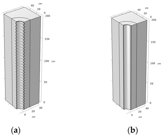
Figure 8.
Geometric modeling: (a) Corrugated casing; (b) Straight casing.
The geometric model was meshed using the COMSOL multiphysics numerical simulation software. Here, the meshing principle is illustrated by using the corrugated casing as an example. The entire model adopted a tetrahedral mesh, as shown in Figure 9a. Due to the small thickness and curved shape of the corrugated pipe, the corrugated pipe section has been refined, as shown in Figure 9b, to ensure the accuracy of the calculations. The model has a total of 1,615,142 tetrahedral networks.

Figure 9.
Mesh: (a) Total; (b) Partial enlargement.
4.4. Boundary and Initial Conditions
Solid model boundary conditions: At the upper boundary of the model, which was subjected to self-weight stress, the overlying load Pz was set to 5 MPa according to the burial depth of 200 m and the average density of 2.5 kN/m3. The side boundaries of the model were subjected to the stress of surrounding rocks, with Px = 6 MPa and Py = 6 MPa. The deformation of the upper-end face of the corrugated casing and the lower boundary of the model were constrained, and the particular boundary displacement was zero, as shown in Figure 10.
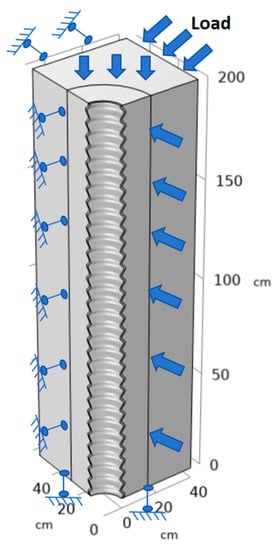
Figure 10.
Boundary conditions.
Temperature field boundary and initial conditions: The initial temperature of the model was set to 273 K. In the steam injection stage, superheated steam with an injection temperature of 873 K was injected. The temperature of the inner surface of the corrugated casing was set to be 873 K as the temperature boundary, whereas the other boundary conditions were adiabatic in nature.
Table 1 shows the material parameters used for simulation.

Table 1.
Parameters used in the simulation.
4.5. Numerical Results
4.5.1. Heat-Transfer Characteristics
Figure 11 shows the heat-transfer characteristics of the corrugated casing-cement formation–shale formation system. The corrugated casing initially reached the injection temperature of 893 K. With the increase in injection time, the temperature of the cement gradually increased, and the high-temperature region expanded into the shale formation. By heating for 40 h, the temperature at the interface between the cement and the shale formation reached 750 K, surpassing the shale pyrolysis temperature of 673 K.
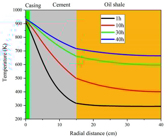
Figure 11.
Radial temperature change of casing-cement sheath–oil shale formation at different times.
4.5.2. Deformation Characteristics
Figure 12 shows the variation in vertical strain of the wellbore casing during the heat-injection process. From Figure 12a, it can be seen that the vertical strain of the corrugated casing showed a periodic change, which was caused by the difference in the deformation of the crest and trough of the corrugated casing. With the increase of the heat-injection duration, the variation trend of the corrugated casing vertical strain did not change significantly. Figure 12b shows that, with the increase in the heat-injection duration, the vertical strain of the straight casing increased significantly, whereas the straight casing expanded thermally. The numerical simulation results were found to be in general agreement with the experimental results, confirming the corrugated structure of the corrugated casing, which can form a mutual occlusion structure with the solidified and hardened cement ring to prevent the corrugated casing from expanding and deforming along the axis direction. The corrugated casing and cement sheath cooperated with each other and showed good ability to resist thermal expansion-deformation.
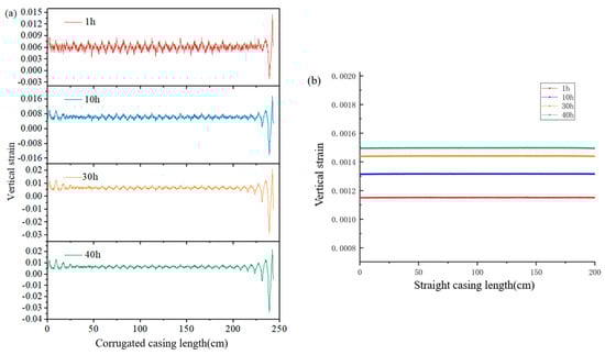
Figure 12.
Vertical strain of corrugated and straight casings at different temperatures: (a) Corrugated casing; (b) Straight casing.
4.5.3. Stress Characteristics
Figure 13 shows the variation of vertical stresses along the wellbore length distribution with time for the corrugated and straight casings. From Figure 12a, it can be seen that the vertical stress on the corrugated casing varied periodically with the change of wave crests and troughs, and the values were mostly within the range of −5 × 10⁸–5 × 10⁸ Pa. With the increase of the heat-injection time, the fluctuation range of the vertical stress did not show obvious changes. With the increase of the heat-injection time, the vertical stress of the straight casing showed a decreasing trend because the vertical stress of the straight casing was mainly influenced by the self-gravity stress and the vertical component of the thermal stress. Moreover, the directions of the self-gravity stress and the vertical component of the thermal stress were opposite to each other. With the increase in temperature, the self-gravity stress remained almost unchanged, while the vertical component force of thermal stress of the casing gradually increased. Meanwhile, the absolute value of the combined force of self-gravity stress and thermal stress gradually became smaller. Due to this reason, the absolute value of vertical stress of straight casing gradually became smaller. The vertical stress of the straight casing was a downward compressive stress, while the values were greater than 1 × 10⁹ Pa. Moreover, the comparison showed that the vertical stress of the corrugated casing was significantly smaller than that of the straight casing, indicating that the corrugated casing had higher stability under the high-temperature condition.
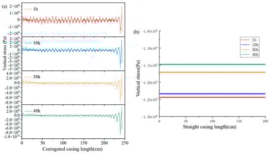
Figure 13.
Vertical stress of corrugated and straight casing at different temperatures: (a) Corrugated casing; (b) Straight casing.
5. Conclusions
In this study, the deformation characteristics of corrugated and straight casings with identical parameters were investigated under uniaxial stress at room temperature using a static-strain acquisition system. Subsequently, the variation of strain was studied over time for the cement-corrugated casing and cement-straight casing configurations under high-temperature conditions using a casing-cement thermal-expansion experimental setup. Finally, a numerical simulation was conducted to explore the synergistic deformation behavior between the casing and the cement sheath. Based upon the results, the following conclusions are drawn.
- (1)
- Under room temperature and unconstrained circumferential conditions, when the corrugated and straight casings exhibited the same amount of deformation under axial loading, the axial load borne by the corrugated casing was significantly lower than that of the straight casing.
- (2)
- When the corrugated casing experienced overall compressive load, the peak regions at various measurement points exhibited tensile strain, while the valley regions displayed a compressive strain. The deformation trend of the local structure within the corrugated casing did not fully align with the overall deformation trend.
- (3)
- Under the constraint of a cement sheath at the same temperature, the horizontal strain at measurement points within the corrugated casing was consistently greater than the vertical strain, whereas the vertical strain at measurement points within the straight casing was always greater than the horizontal strain. Furthermore, under the same temperature conditions, the vertical strain in the corrugated casing was consistently lower than that in the straight casing. The corrugated casing, together with the cement sheath, formed an interlocking structure that prevented thermal expansion-induced deformation of the corrugated casing.
- (4)
- Numerical simulations revealed that the axial stress experienced by the corrugated casing exhibited periodic fluctuations corresponding to the variations in the corrugation peaks and valleys. With the increase in the heating duration, there was no significant change in the numerical fluctuation range of the axial stress. In high-temperature environments, the corrugated casing demonstrated good stability through its interaction with the cement sheath.
Author Contributions
Conceptualization, S.R. and J.Z.; Methodology, S.R.; Funding acquisition, D.Y.; Supervision, D.Y.; Validation, J.Z. and Z.K.; Visualization, G.W.; Project administration, D.Y.; Resources, D.Y.; Writing—original draft, S.R.; Formal analysis, S.R.; Data curation, S.R. and G.W.; Writing—review and editing, S.R. All authors have read and agreed to the published version of the manuscript.
Funding
This research work was supported by the National Key R&D Program (Grant No.: 2019YFA0705501) and the Basic Research Program of Shanxi Province (Grant No.: 20210302123177).
Data Availability Statement
Not applicable.
Conflicts of Interest
The authors declare no conflict of interest.
References
- Keboletse, K.P.; Ntuli, F.; Oladijo, O.P. Influence of coal properties on coal conversion processes-coal carbonization, carbon fiber production, gasification and liquefaction technologies: A review. Int. J. Coal Sci. Technol. 2021, 8, 817–843. [Google Scholar] [CrossRef]
- Li, Q. The view of technological innovation in coal industry under the vision of carbon neutralization. Int. J. Coal Sci. Technol. 2021, 8, 1197–1207. [Google Scholar] [CrossRef]
- Amit, R.K.; Supriya, M. State of the art review on physiochemical and engineering characteristics of fly ash and its applications. Int. J. Coal Sci. Technol. 2022, 9, 9. [Google Scholar]
- Mohr, S.; Wang, J.; Ellem, G.; Ward, J.; Giurco, D. Projection of world fossil fuels by country. Fuel 2015, 141, 120–135. [Google Scholar] [CrossRef]
- Abas, N.; Kalair, A.; Khan, N. Review of fossil fuels and future energy technologies. Futures 2015, 69, 31–49. [Google Scholar] [CrossRef]
- Kang, Z.; Zhao, Y.; Yang, D. Review of oil shale in-situ conversion technology. Appl. Energy 2020, 269, 115121. [Google Scholar] [CrossRef]
- Jiang, X.; Han, X.; Cui, Z. New technology for the comprehensive utilization of Chinese oil shale resources. Energy 2007, 32, 772–777. [Google Scholar] [CrossRef]
- Wang, L.; Zhao, Y.; Yang, D.; Kang, Z.; Zhao, J. Effect of pyrolysis on oil shale using superheated steam: A case study on the Fushun oil shale, China. Fuel 2019, 253, 1490–1498. [Google Scholar] [CrossRef]
- Khalil, A.M. Oil shale pyrolysis and effect of particle size on the composition of shale oil. Oil Shale 2013, 30, 136. [Google Scholar] [CrossRef]
- Alhesan, J.S.A.; Fei, Y.; Marshall, M.; Jackson, W.R.; Qi, Y.; Chaffee, A.L.; Cassidy, P.J. Long time, low temperature pyrolysis of El-Lajjun oil shale. J. Anal. Appl. Pyrolysis 2018, 130, 135–141. [Google Scholar] [CrossRef]
- Crawford, P.M.; Killen, J.C. New challenges and directions in oil shale development technologies. In Oil Shale: A Solution to the Liquid Fuel Dilemma; Ogunsola, O.I., Ed.; Department of Energy: Washington, DC, USA, 2010; Volume 1032, pp. 21–60. [Google Scholar]
- Ma, J.; Xue, L.; Zhao, J.; Bai, F. Numerical simulation and design optimization of temperature field of oil shale in situ pyrolysis and exploitation. Sci. Technol. Eng. 2019, 19, 94–103. [Google Scholar]
- Sun, Y.; Deng, S.; Wang, H. Advances in the Exploitation Technologies and Researches of Oil Shale in the World: Report on 33rd Oil Shale Symposium in US. J. Jilin Univ. 2015, 45, 1052–1059. [Google Scholar]
- Sun, Y.; Guo, W.; Deng, S. The status and development trend of in-situ conversion and drilling exploitation technology for oil shale. Drill. Eng. 2021, 1, 57–67. [Google Scholar]
- He, W.; Sun, Y.; Guo, W.; Shan, X. Controlling the in-situ conversion process of oil shale via geochemical methods: A case study on the Fuyu oil shale, China. Fuel Process. Technol. 2021, 219, 106876. [Google Scholar] [CrossRef]
- Kang, Z.; Zhao, Y.; Yang, D.; Tian, L.; Li, X. A pilot investigation of pyrolysis from oil and gas extraction from oil shale by in-situ superheated steam injection. J. Pet. Sci. Eng. 2020, 186, 106785. [Google Scholar] [CrossRef]
- Kang, Z.; Zhao, Y.; Yang, D.; Zhao, J.; Wang, L. Pilot test of in-situ steam injection for oil and gas production from oil shale and applicability of multi-mode in-situ thermal recovery technology. Acta Pet. Sin. 2021, 42, 1458–1468. [Google Scholar]
- Wang, L.; Zhao, Y.; Yang, D. Investigation on meso-characteristics of in-situ pyrolysis of oil shale by injecting steam. Chin. J. Rock Mech. Eng. 2020, 39, 1634–1647. [Google Scholar]
- Wang, L.; Yang, D.; Zhao, J.; Zhao, Y.; Kang, Z. Changes in oil shale characteristics during simulated in-situ pyrolysis in superheated steam. Oil Shale 2018, 35, 230. [Google Scholar] [CrossRef]
- Wang, X. Mechanism of Gas Migration and Evolution of Casing Pressure during Deep-Water Well Cementing. Ph.D. Dissertation, China University of Petroleum (East China), Dongying, China, 2019. [Google Scholar]
- Dong, W. Safety Analysis of Completion Strings for Steam-Injected Thermal Recovery Wells. Ph.D. Dissertation, China University of Petroleum (East China), Dongying, China, 2018. [Google Scholar]
- Zhao, X.; Han, S.; Yang, X. Mechanical Characteristics Analysis of Casing-Cement Sheath-Formation Multilayer Composite System with Thermo-Structural Coupling Effects. J. Cent. South Univ. 2017, 48, 837–843. [Google Scholar]
- Lian, Z.; Luo, Z.; Bu, H.; Li, C.; Li, C. Mechanical and control measures on casing damage due to annular absence of cement sheath. Oil Drill. Prod. Technol. 2017, 39, 435–441. [Google Scholar]
- Feng, J.; Zhang, M.; Li, D.; Sun, R. Worn-casing burst strength after cement sheath defect. Oil Drill. Prod. Technol. 2012, 34, 48–51. [Google Scholar]
- Jiang, K.; Li, Q.; Chen, Y.; Guo, X.; Fu, Y.; Li, J. Influence of cementing quality on casing failures in horizontal shale gas wells. Gas Ind. 2015, 35, 77–82. [Google Scholar]
- Liu, K.; Gao, D.; Wang, Y.; Yang, Y. Effect of local loads on shale gas well integrity during hydraulic fracturing process. J. Nat. Gas Sci. Eng. 2017, 37, 291–302. [Google Scholar] [CrossRef]
- Xi, Y.; Lian, W.; Fan, L.; Tao, Q.; Guo, X. Research and engineering application of pre-stressed cementing technology for preventing micro-annulus caused by cyclic loading-unloading in deep shale gas horizontal wells. J. Pet. Sci. Eng. 2021, 200, 108359. [Google Scholar] [CrossRef]
- Wang, M.; Hang, X. Finite Element Analysis of Residual Stress Distribution Patterns of Prestressed Composites Considering Interphases. Materials 2023, 16, 1345. [Google Scholar] [CrossRef]
- Gao, L.; Qiao, L.; Liu, Z.; Zhuang, Z.; Yang, H. Numerical Modeling and Cementing Countermeasure Analysis of Casing Shear Damage in Shale Reservoir. China Pet. Mach. 2016, 44, 6–10+16. [Google Scholar]
- Yu, X.; Chen, X.; Ji, Y. Single Factor Analysis of Casing Force Based on the Numerical Simulation. J. Southwest Pet. Univ. 2015, 37, 127–134. [Google Scholar]
- Fan, M.; Liu, G.; Li, J.; Guo, X.; He, M.; Li, M. Effect of Cementing Quality on Casing Stress of Shale Gas Well under Heat-mechanical Coupling. China Pet. Mach. 2016, 44, 1–5. [Google Scholar]
- Fan, M.; Li, J.; Liu, G. Study on Cement Sheath Integrity in Shale Formation Fracturing Process. China Pet. Mach. 2017, 45, 45–49. [Google Scholar]
- Zhao, J.; Wang, L.; Liu, S.; Kang, Z.; Yang, D.; Zhao, Y. Numerical simulation and thermo-hydro-mechanical coupling model of in situ mining of low-mature organic-rich shale by convection heating. Adv. Geo-Energy Res. 2022, 6, 502–514. [Google Scholar] [CrossRef]
- Salimzadeh, S.; Paluszny, A.; Nick, H.M.; Zimmerman, R.W. A three-dimensional coupled thermo-hydro-mechanical model for deformable fractured geothermal systems. Geothermics 2018, 71, 212–224. [Google Scholar] [CrossRef]
- Shi, Y.; Song, X.; Shen, Z.; Wang, G.; Li, X.; Zheng, R.; Geng, L.; Li, J.; Zhang, S. Numerical investigation on heat extraction performance of a CO2 enhanced geothermal system with multilateral wells. Energy 2018, 163, 38–51. [Google Scholar] [CrossRef]
Disclaimer/Publisher’s Note: The statements, opinions and data contained in all publications are solely those of the individual author(s) and contributor(s) and not of MDPI and/or the editor(s). MDPI and/or the editor(s) disclaim responsibility for any injury to people or property resulting from any ideas, methods, instructions or products referred to in the content. |
© 2023 by the authors. Licensee MDPI, Basel, Switzerland. This article is an open access article distributed under the terms and conditions of the Creative Commons Attribution (CC BY) license (https://creativecommons.org/licenses/by/4.0/).