Abstract
The permanent magnet synchronous motor (PMSM) has been widely used in the field of ship electric propulsion due to its advantages of a small size, light weight, low loss, and high efficiency. In this paper, a 100 kW ship-side thruster motor was taken as the research object, and the problem of the high harmonic content of the air gap magnetic flux density in the motor was addressed by designing a rotor eccentricity. On this basis, the hybrid Taguchi method of genetic algorithm was used to optimize the rotor structural parameters with increasing the efficiency and reducting the cost of the motor as the optimization objectives. The results show that the performance and economy of the motor have been greatly improved after optimization. Finally, the motor weight reduction hole was designed, and a prototype was manufactured and tested. The test data are within the allowable range compared with the simulation data, verifying the effectiveness of the multiobjective optimization algorithm proposed in this paper.
1. Introduction
In recent years, with the rapid development of China’s shipping industry, the upgrading and technological advancement of ship equipment has become an important trend in the industry [1,2]. As important power equipment for ships, the performance and quality of ship electric motors directly affect the sailing efficiency and safety of ships. Among many types of motors, permanent magnet synchronous motors are widely used in electric vehicles, aerospace, and shipbuilding industries due to their superior characteristics, such as a high efficiency, high power density, low noise, and low vibration [3]. In particular, in the field of ship electric propulsion, permanent magnet synchronous motors can meet the requirements of a fast response and high-precision control due to their advantages, such as a fast response speed, good adjustment performance, and superior steady-state performance [4]. As a result, the share of permanent magnet synchronous motors in the marine industry is gradually increasing.
The lateral thrust system is responsible for providing lateral thrust in the ship’s propulsion system, ensuring that the ship can leave and dock at the pier on its own. Currently, the lateral thrust system uses lateral thrust motors that are typically installed on the side or rear of the underwater vehicle, connected to the vehicle’s power and control systems by cables, and controlled by the operator through a remote control or autonomous navigation system [5,6]. To meet the complex operational requirements, marine lateral thrust motors often require advanced driving characteristics, such as a high torque density, high efficiency, and high reliability [7]. Therefore, how to meet these key requirements has become a focus of attention for personnel in the field of motor design optimization.
To achieve a high-performance optimization design of motors, traditional optimization algorithms, such as the Nelder–Mead method, response surface method, Taguchi method, etc., have been applied in motor design. Reference [8] used the Nelder–Mead method to optimize the IPMSM for the purpose of minimizing the average loss during the motor’s operating cycle while limiting the power required for the semiconductor inverter. The Nelder–Mead method has the advantages of a small computational cost and fast computing speed, but it is highly dependent on the initial solution and is prone to getting stuck in local minimums [9]. Reference [10] proposes a multiobjective optimization method combining a hierarchical parameter design and response surface method to optimize asymmetrical V-type IPMSM for the purpose of reducing the torque ripple and improving the motor output torque.
The Taguchi method is a robust design method established by Dr. Taguchi in Japan based on orthogonal testing and signal-to-noise ratio techniques. Its core idea is to determine the impact of each factor on the results and find the optimal combination of parameters through methods such as a design matrix and SNR analysis, so as to design more robust and optimized products or systems [11].
Reference [12] uses the Taguchi method to optimize the interior permanent magnet synchronous motor, while reference [13] optimizes the stator punching using the Taguchi method with the slot width, slot height, and slot core height as the design variables, reducing the torque ripple, slotting torque, and stator iron loss. The Taguchi method can significantly reduce the computational cost and improve simulation efficiency, but it has limitations in terms of calculation accuracy and optimal value selection [14].
Traditional optimization methods mainly rely on finite element simulation software for single-objective optimization, and such algorithms are highly dependent on the initial values; optimization results often converge to local optimal points near the initial solution, making it difficult to obtain the optimal parameter values. With the rapid development of computer technology, intelligent optimization design methods represented by global optimization algorithms, such as simulated annealing, the chaos algorithm, the particle swarm algorithms the NSGA-II algorithm, and the genetic algorithm, have gradually emerged through the observation and simulation of natural or social phenomena.
In reference [15], the simulated annealing algorithm was used to optimize the amount of permanent magnets used in the motor to reduce design costs. Reference [16] combined the chaotic algorithm and particle swarm optimization algorithm to optimize the slot shape and other variables of a micro permanent-magnet motor. In reference [17], the particle swarm optimization algorithm and genetic algorithm were combined and used to optimize the permanent magnet linear motor, resulting in a significant reduction in the number of iterations and an accelerated convergence speed. Reference [18] proposes a hierarchical optimization design method for the motor rotor structure, with the objectives of reducing the torque ripple and electromagnetic noise. The NSGA-II algorithm and a univariate parameter method are combined to achieve a high-performance optimization design. Reference [19] uses NSGA-II to optimize the magnet shape, rotor yoke, and stator slot of an 8-pole 48-slot IPMSM and creatively introduces the Nelder–Mead method to solve the geometric constraint repair problem, achieving the maximum motor torque and minimal torque ripple. Reference [20] uses a genetic algorithm to perform multiobjective optimization design on the rotor structure of permanent-magnet synchronous motors, with the optimization objectives of the slotting torque, torque ripple, harmonic distortion rate of the air gap magnetic flux density, and the amplitude of the no-load back electromotive force.
The genetic algorithm simulates the biological evolution process by introducing concepts such as competition, crossover, selection, mutation, and reproduction to select individuals that are suitable for the environment from the population for genetic operations and obtain the individual with the best adaptability to the environment as the optimal solution [21]. Compared with other algorithms, the genetic algorithm is more widely applicable, simpler to operate, and has better optimization results; thus, it is widely used in motor optimization design [22]. However, it also has certain drawbacks, such as a slow convergence speed and the need for a lot of trial and error in parameter tuning. To address this issue, this paper proposes a multiobjective optimization design algorithm based on the hybrid Taguchi method and genetic algorithm. The basic idea of this algorithm is to use the Taguchi method to set the running parameters in the GA optimizer based on the genetic algorithm optimization. The Taguchi algorithm has the advantages of a simple operation and fast computation speed, while the genetic algorithm can be used to handle complex nonlinear problems and has a good global search capability. The combination of the two can improve the efficiency and accuracy of the optimization solution.
This paper aims to design a 100 kW, 3000 rpm permanent magnet synchronous motor suitable for ship electric propulsion. Firstly, a rotor eccentricity design is adopted to optimize the motor performance, addressing the problem of a nonsinusoidal air gap magnetic density waveform and high harmonic content. On this basis, a hybrid Taguchi genetic algorithm is used to improve the permanent magnet size and rotor structural parameters, further enhancing the motor efficiency and reducing the design costs. Lastly, a reduced-weight motor model is designed and a prototype is made, with testing and simulation results compared to validate the rationality of the algorithm.
2. Finite Element Model
2.1. Motor Initial Parameter Design
The interior permanent magnet synchronous motor (IPMSM) is widely used in the field of ship electric propulsion due to its high efficiency, low noise, and low vibration characteristics. The design of the ship propulsion permanent magnet synchronous motor in this paper requires a rated power of ≥100 kW, torque ripple of ≤5%, average torque of ≥340 N·m, stator outer diameter of ≤250 mm, and efficiency meeting the minimum efficiency requirement of 93 % for ship motors. Based on electromagnetic theory and design experience, this paper preliminarily determines the motor structure parameters. Then, after simulation and verification using Maxwell finite element software, a 36-slot 8-pole IPMSM model is obtained as shown in Figure 1, and its structural parameters are shown in Table 1. The permanent-magnet uses high-performance neodymium iron boron material N48UH, which has a high magnetic energy product and excellent high-temperature thermal stability, with a Curie temperature of above 150 °C, and can maintain a good magnetic performance even at high temperatures. The stator and rotor core materials were selected as cold-rolled nonoriented silicon steel sheets with a grade of 50WW470, as shown in Figure 2. The BH curve of this material shows that its saturation magnetic flux density is relatively high, up to 1.6 T, which means that it can achieve higher inductance values in smaller sizes. The BP curve indicates that the hysteresis loss and eddy current loss of the 50WW470 material are both low.
Figure 1.
Finite Element Model of Electric Motor.
Table 1.
Initial parameters of permanent magnet synchronous motor.
Figure 2.
Magnetization Curve of 50WW470.
After simulating the transient magnetic field, the distribution of the no-load flux density of the motor is shown in Figure 3. It can be seen that the tooth flux density of the stator is around 1.5 T and the maximum value of the yoke flux density of the stator is 1.32 T, both of which have not reached saturation. The magnetic flux density near the permanent magnet slot is higher due to end leakage and can reach 2.25 T, with a reasonable distribution of magnetic flux density.
Figure 3.
Electric Motor Flux Map.
2.2. Rotor Eccentricity Design
The air gap between the stator and rotor is a key parameter in the permanent magnet synchronous motor, which directly affects the motor’s stability and the uniformity of its output torque. Due to the magnetic circuit characteristics of the permanent magnet synchronous motor, the air gap magnetic density waveform generally approaches a rectangular wave, and the total harmonic distortion of induced electrical potential is relatively high. Therefore, optimizing the air gap length can improve the performance of the motor.
In this paper, a method using eccentric arc optimization is proposed. Figure 4 shows a comparison of the rotor surface shape within one pole range before and after the eccentric arc optimization, where the red dashed line represents the outer circle of the rotor before the eccentric design. By adjusting the surface shape of the rotor, the air gap length and uniformity can be changed, thus affecting the direction and distribution of the motor flux and changing the inductances of the d-axis and q-axis. To reduce the distortion at the air gap magnetic density zero-crossing position, we used a straight-line connected eccentric arc design. After simulating with Maxwell, the air gap magnetic density waveform before and after optimization is shown in Figure 5a, and the FFT analysis of the air gap magnetic density waveform is shown in Figure 5b. It can be observed that the air gap magnetic density waveform is close to a sine wave after the initial optimization, with the fundamental amplitude increasing from 1.09 T to 1.17 T and the odd harmonic content significantly reduced. Meanwhile, Figure 6 shows that the amplitude of the motor’s induced electromotive force is increased and the waveform tends towards a sine wave after the rotor structure is improved, with the total harmonic distortion reduced, demonstrating the rationality of the optimized design.
Figure 4.
Surface Shape Optimization of Rotor Before and After.
Figure 5.
Comparison of Air Gap Flux Density before and after Optimization.
Figure 6.
Comparison of Back EMF before and after Optimization.
After preliminary rotor structure optimization, the basic performance parameters of the motor are as follow in Table 2:
Table 2.
Comparison of motor performance before and after eccentric design.
Simulation results show that adopting a rotor eccentricity design can effectively improve the performance of permanent magnet synchronous motors. After optimization, the output torque of the motor increased by 3.8% and the torque ripple decreased by 32.4%. However, this design still fails to meet the efficiency standard for marine electric motors (93%). Considering factors such as performance, cost, and reliability, a hybrid genetic algorithm will be used to optimize the rotor and permanent magnet structure of the motor in order to obtain the best motor design scheme.
3. Parameter Optimization Based on Hybrid Taguchi–Genetic Algorithm
3.1. The Principle of Hybrid Genetic Algorithm
This article uses the GA optimizer in ANSYS Maxwell to optimize the permanent magnet synchronous motor using genetic algorithms. Traditional genetic algorithms simulate the “survival of the fittest” mechanism, selecting, crossing, and mutating the initial population to produce individuals that are more adapted to the environment and then continuously reproducing and evolving to obtain the most adapted individual. However, because the various operating parameters of genetic algorithms have different and interrelated effects, the traditional trial-and-error method is not only inefficient but also unscientific. Therefore, this paper proposes a hybrid Taguchi method genetic algorithm, which uses the Taguchi method to determine the operating parameters of the optimizer and, after simulation calculations, determines the optimal design parameter combination for the motor. The process of applying genetic algorithms to the optimization design of motors is shown in Figure 7.
Figure 7.
Genetic Algorithm Flowchart.
3.2. Establishment of Optimization Model for Electric Motors
In general, the universal mathematical model for the optimization of permanent magnet synchronous motors is as follows:
where is the objective function, is the constraint condition, x is the optimization variable, and m is the number of constraint conditions.
In the genetic algorithm, the cost function determines the direction of parameter optimization; in general, the minimum point of the cost function is the optimal point searched by the genetic algorithm. In the multiobjective optimization of PMSM, to determine the optimal direction of parameters, weight coefficients are assigned to each objective function according to the importance of each optimization objective (the larger the , the more important the objective function). The total cost function is the sum of the product of each objective function and the weight coefficient.
In the equation, represents the i-th objective function expression; represents the conditional operators >, <, and =; is the given target value for the i-th objective function; and is the objective residual, which represents the deviation of the objective function simulation response value from the given target value range. If it is within the objective function range, it is 0; if it does not meet the criteria, it depends on the difference between the response value and the target value.
The selections of the minimum air gap length , permanent magnet , permanent magnet thickness , internal magnetic bridge width , and edge magnetic bridge width as design variables in the rotor structure are shown in the Figure 8. The values of these parameters are predefined, and their range is determined as shown in Table 3.
Figure 8.
Rotor structural parameters.
Table 3.
Range of values for structural parameters to be optimized.
The main design optimization directions for a ship-based azimuth thruster are to improve the efficiency and reduce the material usage. Improving the motor efficiency can reduce the energy consumption and fuel costs, as well as increase the overall economic efficiency of the vessel. Reducing the material usage can lower the manufacturing costs, reduce the weight of the entire vessel, and thereby increase its payload capacity and sailing speed. The formula for calculating the motor efficiency is as follows:
In the equation, is the average output torque of the motor; is the rated angular velocity of the motor; is the iron loss of the motor; is the copper loss; and is the friction and windage losses of the motor. Relative to copper and iron losses, the windage losses of the motor can be ignored. Considering that the copper loss of the motor is related to the current flowing through the armature and the winding resistance, the key factor affecting efficiency changes is mainly concentrated in the iron loss and torque value. This article selects three indicators, the average torque , the permanent magnet , and the motor iron loss , as optimization targets for optimization. The optimization goal of is set to 372 N·m, with a range of values set from 367 N·m to 372 N·m. The objective function for the torque performance is as follows:
When the average output torque is 367 N·m, the value of the objective function is 1. When the average output torque reaches its maximum value of 372 N·m, the value of the objective function reaches its maximum of 10.
In the design of permanent magnets for motors, in order to maintain a uniform and stable magnetic field, the axial length of the permanent magnet is usually equal to that of the motor iron core. Therefore, the amount of permanent magnet used is represented by the area . The optimization goal for the is 250 mm with a range from 250 mm to 256 mm. The objective function for the weight of the permanent magnet is as follows:
The optimization objective of the for iron loss is 1.099 kW, with a range of values set from 1.099 kW to 1.112 kW. The objective function for the motor iron loss is as follows:
After defining the expressions for each objective function, if is set to ≤, then the constraint formulas for the four objective functions are as follows:
Based on the importance of each optimization sub-goal, assign weights to each sub-goal as follows: , , . The formula for calculating the total cost function is shown below:
4. The Application of Taguchi Method
4.1. Determining GA Parameters Using the Taguchi Method
To ensure the coordination between the algorithm structure and parameters and improve computational accuracy, the Taguchi method should be used to select the parameters of the GA optimizer. The common parameters include the population size M, crossover rate mutation rate , and maximum iteration times. When the maximum iteration times are set to 100 and other parameters are kept default, it is important to pay attention to the reasonable range of parameter values. If the population size is too large, the algorithm solving speed will decrease; however, if it is too small, the diversity of the population will be affected. A high crossover rate will destroy the excellent mode of the population, while a low crossover rate will affect the generation speed of new individuals. The mutation rate is mainly used to control the mutation operation. A small value may reduce the diversity of the population, leading to a decrease in the search performance of the algorithm, while a large value may affect the probability of producing excellent individuals. Generally, the range of the population size M is 20–100, the range of the crossover rate is 0.4–0.8, and the range of the mutation rate is 0.001–0.1.
The Taguchi method, as a design scheme for multivariate optimization systems, is applied to motor design. The operating procedure involves arranging experiments according to an orthogonal table and conducting variance analysis on the experimental data to determine the degree of influence of each optimization factor on the performance index and determine the optimal combination of parameters. The implementation process of the method is shown in Figure 9.
Figure 9.
Taguchi Optimization Process Diagram.
To establish an orthogonal array and determine the population size, crossover frequency, and mutation frequency as three optimizing factors, with each factor having levels, the following equations can be used to calculate the mean and variance:
In the formula, represents the response value of the kth optimization factor in the jth trial (such as the torque, iron loss, and magnet area), represents the mean of all response values corresponding to the kth optimization factor, and represents the sample variance of all response values corresponding to the kth optimization factor. The results of the determined orthogonal table calculations are shown in Table A1. According to the calculation results, the optimal torque optimization variable combination for IPMSM is M—3, —3, and —2, while the optimal variable combination for minimizing the amount of permanent magnets and iron loss is M—2, —2, and —3.
As shown in Table 4, the proportion of the influence of each optimization factor on the performance indicators was obtained through variance calculation. The population size has a significant influence on both the torque and the permanent magnet area, while the mutation probability and crossover probability have a significant impact on the iron loss of the motor. Since the design aims to improve the motor efficiency, reduce the iron loss, and reduce the permanent magnet usage, the optimal variable combination selected is M—2, —2, and —3, which has a population size of 50, a crossover probability of 0.7, and a mutation probability of 0.1.
Table 4.
Analysis of variance table.
4.2. Optimization Result
After building the final electromagnetic design and creating an Ansoft simulation model, the values of the motor torque, iron loss, and efficiency were calculated at an input current of 220 A and a rated speed of 3000 rpm. The performance indicators before and after optimization were compared. As shown in Table 5 and Figure 10, it can be seen that, after the optimization of the genetic algorithm, the average output torque increased by 1.65%, the motor efficiency increased by 4.73%, and the material usage of permanent magnets was reduced by 2.21%. The optimized motor model meets the efficiency requirements for ship-use motors while reducing the amount of permanent magnets used and improving the economic efficiency of ships.
Table 5.
Motor structure and performance parameters before and after optimization by genetic algorithm.
Figure 10.
Torque waveform of motor before and after optimization.
5. Simulation and Performance Testing
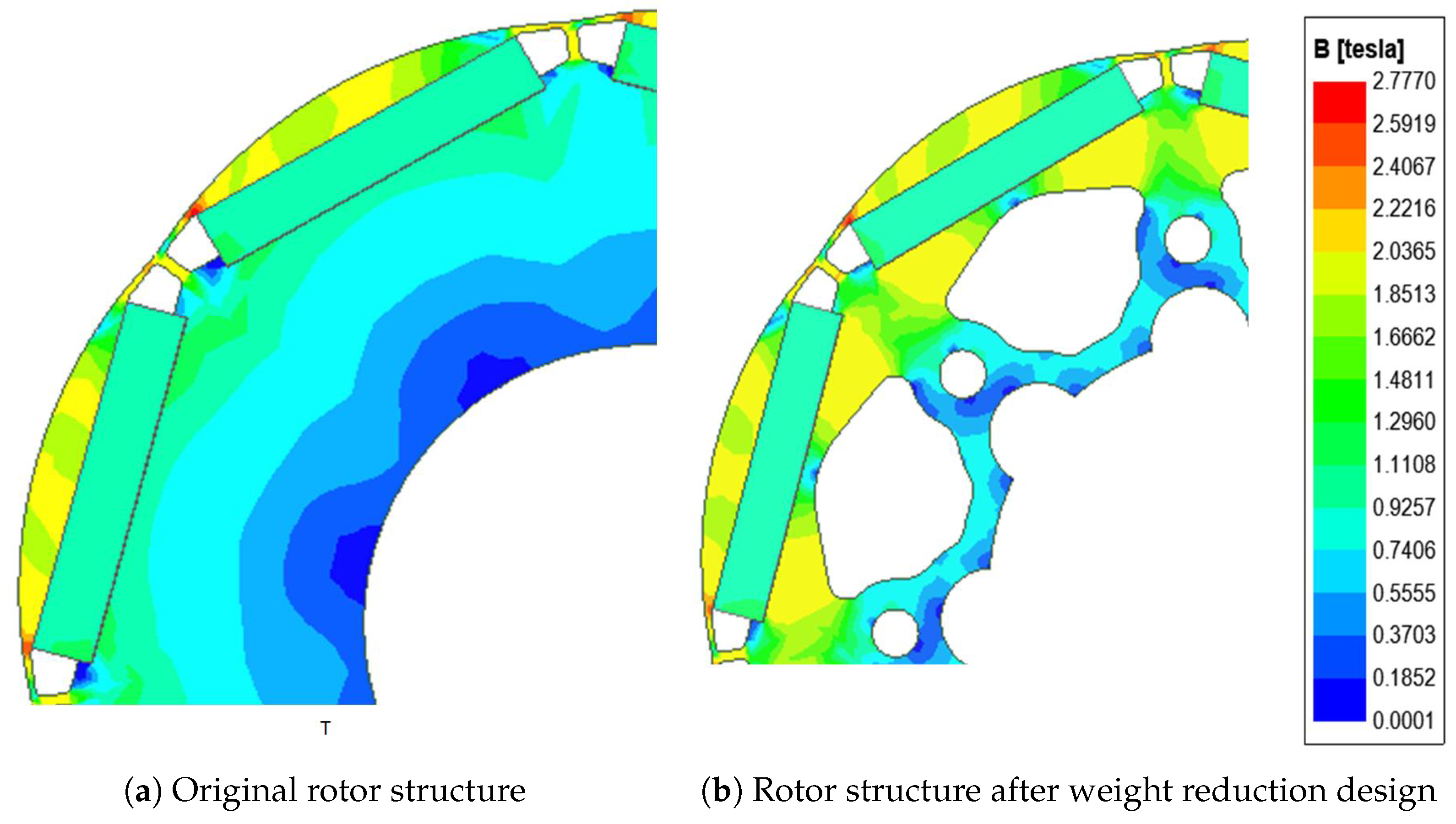
5.1. Design for Weight Reduction in Motors
After the algorithm optimization, the rotor laminations of the motor are designed with weight-reducing holes to improve the power density. A reasonable selection of the shape and position of weight-reducing holes can reduce the weight, optimize the magnetomotive force distribution, and increase the motor’s heat dissipation area without changing the motor’s performance. The improved and original motors were simulated, and the unloaded magnetic flux distribution of the rotor was obtained, as shown in Figure 11. It can be seen that there is little magnetic density variation in the area near the axis, and the weight-reducing design enhances the magnetizing effect of the embedded rotor structure, reducing the magnetic leakage in the motor. After comparing the motor performance before and after adding the weight reduction holes, Table 6 shows that the rotor weight was reduced from 19.71 kg to 11.18 kg before and after optimization, and the no-load counter-electromotive force and average torque did not change much.
Figure 11.
Comparison of magnetic flux density distribution before and after weight reduction design.
Table 6.
Performance comparison of motor before and after weight reduction design.
As the core component of an embedded permanent magnet synchronous motor, the rotor is subjected to various forces, such as electromagnetic force, thermal stress, and centrifugal force. It is necessary to validate the mechanical strength of the IPMSM rotor using Ansys Workbench simulation software to avoid a deformation or fracture of the rotor’s magnetic barriers and insulation bridges during high-speed operation.
As shown in Figure 12, the maximum stress on the rotor is 66.67 Mpa when the rotor rotates at a maximum speed of 8000 rpm, which is much smaller than the yield strength of the silicon steel material (330 Mpa). It can be seen that the stress and deformation of the rotor caused by centrifugal force are much smaller than the strength limit of the corresponding material when the motor is running, and the equivalent stress and deformation displacement are within the safe range. Therefore, the rotor is not in danger of fracture, and it can be determined that the design of the rotor can ensure the normal operation of the motor.
Figure 12.
Stress distribution in rotor core.
5.2. Simulation of Motor Temperature Rise
Motor losses can cause the internal temperature to rise, which can negatively impact the motor performance and lifespan.To evaluate the thermal stability of the motor, a common method is to simulate the motor temperature rise and predict the temperature distribution after long-term operation. In the special environment around ships, seawater contains a large amount of salt and other chemicals, which can corrode the motor if used for cooling, thereby affecting its lifespan. The commonly used water cooling method requires regular maintenance of the cooling system, increasing the equipment costs and workload. Therefore, the motor designed in this paper is fully enclosed and uses natural air cooling to eliminate issues such as corrosion and maintenance.
In this study, we established a 2D model of the motor and conducted a transient thermal simulation using ANSYS Workbench to investigate the temperature change of the motor after operating under a constant load for 30 min and then being turned off. To better simulate the actual working conditions, we set the initial environmental temperature at 56 °C and the convective heat transfer coefficient to 15, taking into account the effect of convection. The distribution of the motor temperature rise after 30 min of simulation is shown in Figure 13. The copper wire is the part with the highest power density in the motor, so its temperature rise is also the highest, reaching 138.69 °C. The temperature rise then gradually decreases from the air gap to the rotor and reaches 119.57 °C at the motor shaft. The temperature distribution contour map shows that the motor’s temperature rise is still relatively high. The motor’s insulation is designed to be F-class, so there is still some margin in the winding’s ability to withstand such temperature rises.
Figure 13.
Transient temperature field simulation of motor.
5.3. Prototype Performance Testing
After the weight reduction hole design, a prototype of a 100 kW stator and rotor, as shown in Figure 14, was produced based on the optimized final solution. In order to verify the performance of the permanent magnet synchronous motor under actual working conditions, torque-efficiency testing was carried out on the motor, and an experimental platform for motor drag testing was built as shown in Figure 15. The experimental testing platform is mainly composed of load motors, test prototypes, torque sensors, and other experimental equipment, where number 1 in the figure corresponds to the tested prototype, number 2 corresponds to the torque sensor, and number 3 corresponds to the load motor.
Figure 14.
Physical image of prototype.
Figure 15.
Motor testing platform.
Under the condition of a rated speed at 3000 rpm, a load test was performed on the prototype. is set as the rated load. In the test, the motor was subjected to a 0.2 load, which was gradually increased to 1.2 . The torque test data of the motor is shown in Table A2. During this process, the efficiency of the motor was measured, and the motor torque-efficiency curve, as shown in Figure 16, was obtained. The trend indicates that the motor efficiency gradually increases as the load increases. It is worth noting that the motor efficiency has reached its maximum value when the load approaches the rated torque, and, even if the load continues to increase, the motor efficiency will not significantly improve. At the same time, the curve also indicates that the motor has a certain carrying capacity and can withstand overload work within a certain range, but long-term overloading may shorten the motor life or directly cause damage. Overall, these results reveal the performance of the motor under specific load conditions and provide a useful reference for the effective operation and maintenance of the motor.
Figure 16.
Motor torque-efficiency curve.
In the back electromotive force test, the prototype was three-phase open-circuited, and a load motor drove the prototype to rotate through the coupling, running at the rated speed of 3000 rpm. In the experiment, the high-voltage differential probe was used to read the induced EMF of the AB phase of the prototype into the oscilloscope for data processing, obtaining the measured back EMF waveform. As shown in Figure 17, the comparison with the simulation results indicates that the test data are basically consistent with the simulation results, verifying the accuracy of the simulation calculation.
Figure 17.
Back electromotive force waveform.
The temperature variation of the test motor winding was measured by the resistance method, and the curve is shown in Figure 18. At the beginning of the experiment, the winding temperature was about 56 °C. As the working time of the motor increased, the winding temperature gradually increased until it reached a near-equilibrium state after 30 min, with a temperature of 143 °C. Thereafter, the temperature change was not significant, indicating that the motor had reached a thermal equilibrium state. Since the insulation level of the motor was F-class, the maximum allowable temperature was 155 °C, so the winding temperature rise was within the allowable range.
Figure 18.
The temperature variation curve of the test motor winding.
As shown in Table 7, By comparing the simulation results with the actual measurements, it was found that there was a certain error between the simulated and measured winding temperatures after the motor had been running for 30 min, but it was within 5 °C, which was a reasonable error. This was because the simulation simplified the model, while the actual motor casing had external heat dissipation fins to enhance the heat dissipation. In addition, the internal losses of the motor during thermal simulation analysis, calculated by finite element and analytical methods, were generally smaller than the actual losses, resulting in the simulated winding temperature being lower than the actual measured value.
Table 7.
Comparison of simulated and measured motor parameters.
Under rated conditions, the average values of the back electromotive force and efficiency error of the motor are not significant. However, the motor will experience losses in actual operation, resulting in a decrease in the torque, so the actual measured value of the motor torque is usually lower than the simulation value. Nevertheless, this deviation is small and does not affect the normal operation of the motor. Experimental results show that the motor can work continuously for more than 30 min while the winding temperature remains within the allowable operating range, proving that the performance of the motor meets the design requirements and can meet the actual working needs.
6. Conclusions
This paper presents a hybrid genetic algorithm optimization design for marine permanent magnet synchronous motors, which effectively improves the efficiency and economy of the electric propulsion system. Firstly, the motor air gap magnetic density waveform was optimized by designing the rotor eccentricity distance, reducing the content of back electromotive force harmonics. Subsequently, a hybrid Taguchi genetic algorithm was used to multiobjectively optimize a part of the rotor’s structural parameters of the motor. After finite element simulation, the results show that the optimized motor torque increased by 1.65% and remained essentially the same, while the efficiency increased by 4.73% and the amount of permanent magnet material decreased by 2.21%. The feasibility and practicality of this optimization algorithm were verified by thermal simulation analysis and prototype testing of the final motor model. Additionally, the research findings of this paper provide a reference for the application of permanent magnet synchronous motors in the field of ship electric propulsion, offering a feasible solution for improving the efficiency and reducing the cost of ships.
Author Contributions
Conceptualization, Y.S.; investigation, Y.F.; methodology, Y.F., Q.Z. and Q.L.; resources, Y.S., Y.F. and Q.Z.; writing—original draft, Q.Z. and Q.L.; writing—review and editing, Y.S. and Y.F. All authors have read and agreed to the published version of the manuscript.
Funding
This research received no external funding.
Institutional Review Board Statement
Not applicable.
Informed Consent Statement
Not applicable.
Data Availability Statement
Not applicable.
Acknowledgments
The authors would like to thank the members of the Key Laboratory of Marine Intelligent Equipment and System (Ministry of Education) and China Ship Development and Design Center for their help in this study.
Conflicts of Interest
The authors declare no conflict of interest.
Abbreviations
The following abbreviations are used in this manuscript:
| PMSM | Permanent Magnet Synchronous Motor |
| IPMSM | Interior Permanent Magnet Synchronous Motor |
| SNR | Signal-to-Noise Ratio |
| NSGA-II | Nondominated Sorting Genetic Algorithm II |
| GA | Genetic Algorithm |
| SA | Simulated Annealing |
| PSO | Particle Swarm Optimization |
| FFT | Fast Fourier Transform |
| EMF | Electromotive Force |
Appendix A
Table A1.
Orthogonal table of GA optimizer parameters.
Table A1.
Orthogonal table of GA optimizer parameters.
| Number | Population Size | Crossover Probability | Mutation Probability | Average Torque (N·m) | Permanent Magnet Area (mm) | Iron Loss of the Motor (kW) | Efficiency (%) |
|---|---|---|---|---|---|---|---|
| 1 | 20 | 0.55 | 0.001 | 380.24 | 302.59 | 1.1597 | 96.39 |
| 2 | 20 | 0.7 | 0.05 | 389.49 | 341.05 | 1.1325 | 96.54 |
| 3 | 20 | 0.85 | 0.1 | 398.33 | 302.97 | 1.1422 | 96.60 |
| 4 | 50 | 0.55 | 0.05 | 400.99 | 302.70 | 1.1455 | 96.62 |
| 5 | 50 | 0.7 | 0.1 | 373.39 | 250.33 | 1.1243 | 96.39 |
| 6 | 50 | 0.85 | 0.001 | 397.39 | 308.90 | 1.1561 | 96.57 |
| 7 | 80 | 0.55 | 0.1 | 403.10 | 390.29 | 1.1447 | 96.64 |
| 8 | 80 | 0.7 | 0.001 | 380.27 | 255.68 | 1.1382 | 96.43 |
| 9 | 80 | 0.85 | 0.05 | 409.50 | 338.65 | 1.1467 | 96.70 |
Table A2.
Load testing Data.
Table A2.
Load testing Data.
| Load Torque (N·m) | Motor Input Voltage (V) | Motor Input Current (A) | Motor Input Power (kw) | Power Factor | Efficiency (%) |
|---|---|---|---|---|---|
| 306.19 | 46.62 | 23.93 | 0.94 | 90.833 | |
| 316.88 | 86.99 | 45.73 | 0.92 | 94.861 | |
| 327.16 | 127.23 | 67.73 | 0.9 | 96.096 | |
| 336.32 | 167.38 | 89.73 | 0.88 | 96.652 | |
| 346.47 | 208.16 | 112.031 | 0.86 | 96.843 | |
| 354.54 | 247.58 | 132.951 | 0.84 | 96.819 |
References
- Nuchturee, C.; Li, T.; Xia, H.P. Energy efficiency of integrated electric propulsion for ships—A review. Renew. Sustain. Energy Rev. 2020, 134, 110–145. [Google Scholar] [CrossRef]
- Jin, X. Research on status, problems and countermeasures of china’s shipping industry development. Product. Res. 2013, 4, 3. [Google Scholar]
- Wang, X.; Li, W.L.; Cheng, S.K. Prospects for development of permanent magnet synchronous motors. Micromotor 2007, 4, 4. [Google Scholar]
- Deng, S.X.; Shen, X. Application and simulation of permanent magnet motor in ship power propulsion. Navig. Technol. 2005, 4, 43–46. [Google Scholar]
- An, Q.; Sun, L.; Li, B. Control system of permanent magnet synchronous motor for submarine lateral thruster without position sensor. J. Dalian Marit. Univ. 2007, 33, 4. [Google Scholar]
- Long, F.; Wang, M.; Yang, J. Research on bow thruster and its application. Ship Electr. Technol. 2005, 2, 6–9. [Google Scholar]
- Chen, J. Characteristics of operation and development trend of marine electric motors. Shandong Sci. Technol. 2021, 5, 42–45. [Google Scholar]
- Dmitrievskii, V.; Prakht, V.; Kazakbaev, V.; Anuchin, A. Comparison of interior permanent magnet and synchronous homopolar motors for a mining dump truck traction drive operated in wide constant power speed range. Mathematics 2022, 10, 1581. [Google Scholar] [CrossRef]
- Nelder, J.A.; Mead, R. A simplex method for function minimization. Comput. J. 1964, 7, 308–313. [Google Scholar] [CrossRef]
- Liu, G.; Wang, Y.; Chen, Q. Multi-objective optimal design of asymmetric V-shaped built-in permanent magnet synchronous motor. J. Electr. Eng. Technol. 2018, 33, 385–393. [Google Scholar]
- Liu, G.; Ren, S. Taguchi Method and Robustness Design. Electrotech. Electr. 2010, 10, 53–57. [Google Scholar]
- Wang, X.; Zhang, L.; Xu, W. Multi-objective Optimization Design of Built-in Permanent Magnet Synchronous Motor Based on Taguchi Method. Micromotor 2016, 49, 1–5. [Google Scholar]
- Qiu, R.L.; Hua, Q.S. Optimization of stator lamination based on taguchi method. Small Spec. Electr. Mach. 2020, 48, 13–16. [Google Scholar]
- Chen, S.; Zhang, Z.; Li, J. Application of Taguchi Method in Multi-Objective Optimization Design of Permanent Magnet Synchronous Motor. Micromotor 2021, 54, 17. [Google Scholar]
- Xu, Y.; Tang, R. Application of Simulated Annealing Algorithm in Optimization Design of Permanent Magnet Synchronous Motor. Electr. Eng. 2000, 2, 8–10. [Google Scholar]
- Chen, D.; Sun, C.; Liu, Z. Optimization Design of Micro Permanent Magnet Motor Based on Hybrid Algorithm of Chaotic Particle Swarm. J. Shenyang Univ. Technol. 2006, 6, 614–618. [Google Scholar]
- Wei, H.; Jiao, L.; Cheng, Z. Optimization Design of Permanent Magnet Linear Motor Based on Improved Particle Swarm Algorithm. Micromotor 2012, 45, 1–3. [Google Scholar]
- Yang, S.M.; Ma, Q. Multi-objective optimization of rotor structure of permanent magnet synchronous motor based on hierarchical optimization strategy. J. Shanghai Univ. Eng. Technol. 2022, 36, 369–377. [Google Scholar]
- Khoshoo, B.; Blank, J.; Pham, T.; Deb, K.; Foster, S. Optimized Electric Machine Design Solutions with Efficient Handling of Constraints. In Proceedings of the 2021 IEEE Symposium Series on Computational Intelligence (SSCI), Orlando, FL, USA, 5–7 December 2021; pp. 1–8. [Google Scholar]
- Chuprin, A.D.; Batchelor, J.C.; Paker, E.A. Design of convoluted wire antennas using a genetic algorithm. IEEE Proc. Microwaves Antennas Propag. 2001, 148, 323–326. [Google Scholar] [CrossRef]
- Zhao, X.; Sun, Z.; Xu, Y. Multi-Objective Optimization Design of Permanent Magnet Synchronous Motor Based on Genetic Algorithm. In Proceedings of the 2020 2nd International Conference on Machine Learning, Big Data and Business Intelligence (MLBDBI), Shanghai, China, 23–25 October 2020; pp. 405–409. [Google Scholar]
- Zhang, Y.; Du, R.; Zhao, X.; Ye, Q. Optimization of motor noise based on multi-objective genetic algorithm. Microtechnology 2020, 48, 21–25. [Google Scholar]
Disclaimer/Publisher’s Note: The statements, opinions and data contained in all publications are solely those of the individual author(s) and contributor(s) and not of MDPI and/or the editor(s). MDPI and/or the editor(s) disclaim responsibility for any injury to people or property resulting from any ideas, methods, instructions or products referred to in the content. |
© 2023 by the authors. Licensee MDPI, Basel, Switzerland. This article is an open access article distributed under the terms and conditions of the Creative Commons Attribution (CC BY) license (https://creativecommons.org/licenses/by/4.0/).