Article

Analysis of Torque Ripple in V-Shape Interior Permanent Magnet Machine Based on General Airgap Field Modulation Theory

School of Electrical Engineering, Southeast University, Nanjing 210000, China
*
Author to whom correspondence should be addressed.
Energies 2023, 16(12), 4586; https://doi.org/10.3390/en16124586
Submission received: 8 May 2023 / Revised: 31 May 2023 / Accepted: 6 June 2023 / Published: 8 June 2023

Abstract

:
This paper proposes a novel torque ripple model of V-Shape interior permanent magnet (IPM) synchronous machine based on the general field modulation theory (GAFMT). Firstly, the magnetic field modulation behavior of a 12-stator-slot/8-rotor-pole (12/8) IPM machine is discussed, where the expressions of permanent-magnet-excited (PM-excited) and armature fields are derived. Secondly, the total torque ripple is divided into three components, namely, the PM-excited cogging torque, the armature cogging torque, and the modulation torque ripple. Additionally, the relationship between the field harmonics and the torque ripple is discussed based on the GAFMT. Then, a finite element analysis (FEA)-assisted dual fast Fourier transformation (FFT) method is proposed to obtain the accurate value of the field amplitude for torque ripple calculation. The field analysis results based on the GAFMT and the proposed torque ripple are then validated by comparing their results with those obtained from the FEA simulations, and a good agreement is observed, demonstrating the effectiveness of the field analysis and the proposed torque ripple model. Finally, experiments on a prototype 12/8 IPM machine demonstrate the validity of the torque ripple model, providing an effective method for torque ripple suppression of IPM machines.

1. Introduction

V-Shape interior permanent magnet (IPM) synchronous machine is a typical topology with a wide range of applications in servo [1], electric vehicle [2], and industrial robotics [3] due to its high power density, high efficiency, and wide speed range. The torque ripple of IPM machines is a major concern in these high-quality applications, which will produce mechanical vibration and reduce the motion performance [4].
The mechanism of torque ripple generation of IPM machines is complex and still unclear because it is related to the time and space harmonics of magnetic fields due to permanent magnet (PM) and armature winding [5]. Therefore, to study the mechanism of torque ripple, the first step is to analyze the magnetic field characteristics in the airgap. However, conventional electrical machine theories, such as the cross-field theory for AC machines [6], the magnetic equivalent circuit theory for regular machines [7], and the rotating magnetic field theory [8], are usually applied to model the fundamental magnetic field while neglecting the harmonic field.
Recently, a general airgap field modulation theory (GAFMT) was proposed [9], which models all the electrical machines in a generalized way by three key components, namely the excitation source, the modulator, and the filter (armature winding), and thus, the characteristics of various magnetic field harmonics can be investigated. The GAFMT can not only be used to analyze the performance of “non-conventional” machines [10], e.g., flux switching PM (FSPM) machine [11], vernier machine (VM) [12], and flux-reversal PM machine (FRPM) [13], etc., but also conventional machines [14,15], providing new ideas for machine design and analysis.
While the GAFMT has been proved to be effective in the analysis of spatial distribution of field harmonics [16], it still has flaws in the amplitude analysis of field harmonics, since the permeability function is usually simplified in the analysis process. The finite element analysis (FEA) method can deal with the influence of complex structures and slotting effects on the magnetic fields and therefore significantly improve the field amplitude analysis accuracy [2,17,18]. Hence, to further improve the ability to analyze the amplitude of field harmonics for torque ripple calculation, this paper proposes an FEA-based dual fast Fourier transformation (FFT) method to extract the amplitudes from the magnetic fields.
Further, based on the combination of GAFMT and FEA-based analysis method, an accurate torque ripple model for IPM machines is proposed, which allows an intuitive description of the torque ripple generation mechanism and quantifies the contribution of each magnetic field harmonic to the total torque ripple. In addition, since the maximum torque per ampere (MTPA) method is usually applied in the IPM machines, the effect of the armature current phase on torque ripple is also investigated based on the proposed torque ripple model.
The organization of the rest of this paper is as follows. The field modulation behavior of IPM machines is analyzed in Section 2, and the torque ripple model and the relationship between the field harmonics and the torque ripple are discussed in Section 3. Then, an FEA-assisted dual FFT method is proposed in Section 4 to derive the detailed torque ripple model. Then, simulations on a 12/8 IPM machine are conducted through FEA together with a comparison with the results from the proposed model in Section 5. The experimental verifications are presented in Section 6, followed by the conclusion drawn in Section 7.

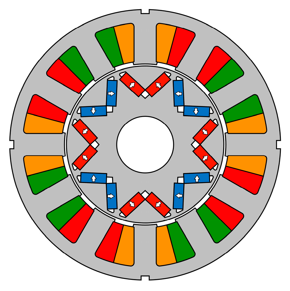
2. Field Modulation Behavior of V-Shape IPM Machine

From the GAFMT perspective, the V-Shape IPM machine can be considered as a class of salient pole reluctance motor, both in terms of its excitation and armature fields modulated by the salient stator/rotor pole. However, the field modulation behavior is not exactly the same for both fields. In the following part, the modulation behavior of the V-Shape IPM is introduced in detail with the aid of the GAFMT.

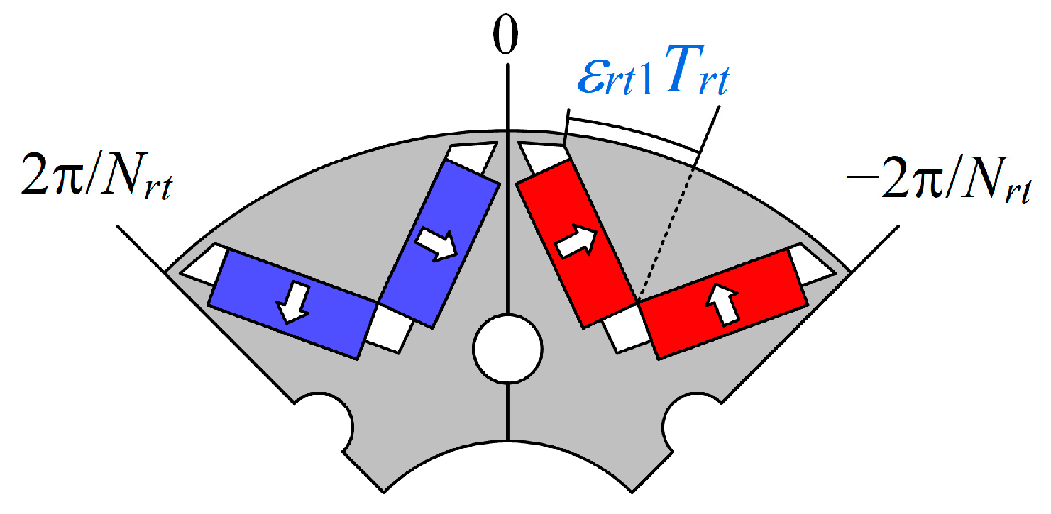
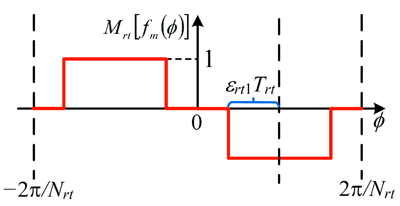
2.1. Rotor Modulation of PM-Excited Field

To illustrate the rotor modulation behavior for the PM-excited field, the stator is considered as a non-slot structure temporarily, and the rotor modulator structure seen from the PM-excited field is shown in Figure 1, where ε r t 1 is the pole–arc ratio, N r t is the rotor pole number, T r t (rad) is the radian of unit rotor modulator (2π/Nrt). As PMs are installed in the V-Shape slots, most of the PM fluxes flow from the silicon steel within the clamping angle of PMs to the stator silicon steel through airgap, and the remaining PM fluxes flow to adjacent PMs through the flux leakage path provided by the magnetic bridge. Hence, there are few PM fluxes in the airgap area corresponding to the bridge. The distribution function of the PM flux after the modulation of the rotor pole can be described as a segmental function in Equation (1), as shown in Figure 2.
M r t f m ϕ = 0 , 2 π N r t < ϕ < π N r t ε r t 1 T r t 1 , π N r t ε r t 1 T r t < ϕ < π N r t + ε r t 1 T r t 0 , π N r t + ε r t 1 T r t < ϕ < π N r t ε r t 1 T r t 1 , π N r t ε r t 1 T r t < ϕ < π N r t + ε r t 1 T r t 0 , π N r t + ε r t 1 T r t < ϕ < 2 π N r t
Considering the rotation of the rotor modulator, Equation (1) can be transformed into the Fourier series form as
M r t f m ϕ , t = v C m r v sin v N r t 2 ϕ ω t
where ϕ is the mechanical angle along the circumference in the modulator-fixed reference frame. M r t f m ϕ , t represents the circumference distribution of the rotor-modulated PM-excited field. v is a positive integer, which represents the modulation order. ω (rad/s) is the mechanical rotation speed.   t (s) is time, and C m r is the rotor modulation coefficient, which can be described as
C m r v = 4 π v sin 2 π v ε r t sin π v 2

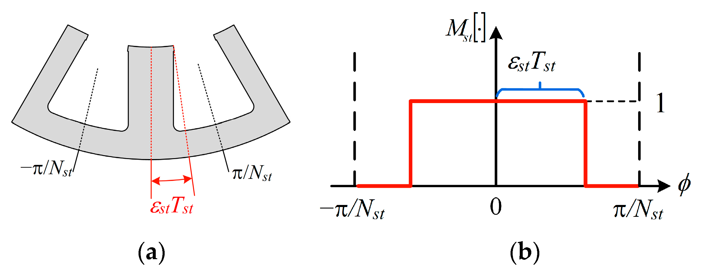
2.2. Stator Modulation of PM-Excited Field

The stator modulator structure for the PM-excited field is shown in Figure 3a, and the operator function shown in Figure 3b can be described as
M s t · = 2 ε s t + l 2 π l sin 2 π l ε s t cos l N s t ϕ
where l is a positive integer, which represents the modulation order. N s t is the number of the stator tooth. T s t is the radian of the unit stator modulator ( 2 π / N s t ). ε s t is half of the pole–arc ratio of stator tooth, and M s t · represents the stator modulator operator.

2.3. Stator Modulation of Armature Field

The winding function shown in Figure 4 can be described as
W a ϕ = v 2 π v sin π v 3 cos v p ϕ W b ϕ = v 2 π v sin π v 3 cos v p ϕ 2 π 3 W c ϕ = v 2 π v sin π v 3 cos v p ϕ + 2 π 3
where p is the rotor pole pairs. W a , W b , and W c represent the winding function of phase A , B , and C respectively.
Considering the armature current as
I a = δ I m δ sin δ p ω t I b = δ I m δ sin δ p ω t 2 π 3 I c = δ I m δ sin δ p ω t + 2 π 3
where δ is a positive integer, which represents the order of current harmonics. I m δ is the current amplitude of δ t h harmonic. I a , I b , and I c represent the armature current of phase A , B , and C , respectively.
Multiplying Equation (5) by Equation (6), the stator-modulated armature excited field can be described as
M s t f a ϕ , t = δ v C a s v , δ sin v p ϕ ± δ p ω t
where C a s is
C a s v , δ = 3 2 2 π v sin π v 3 I m δ

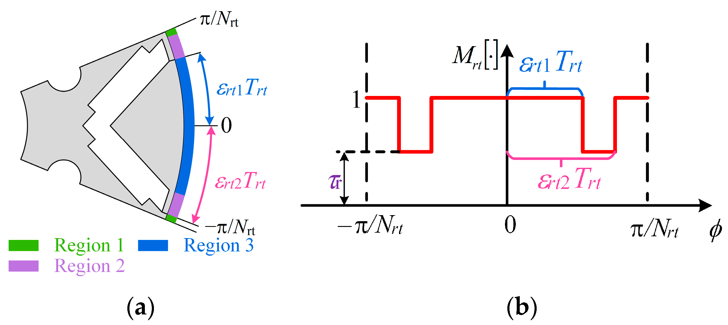
2.4. Rotor Modulation of Armature Field

Figure 5 shows the unit rotor modulator structure and the modulator operator function. The modulator can be divided into three regions along the airgap, as shown in Figure 5a. The armature field fluxes tend to pass through the airgap area corresponding to regions 1 and 3, since the magnetic bridge is thin and usually saturated by PM fluxes. Thus, the rotor modulator function can be described in Figure 5b. The positive half-period expression of the modulation operator in Figure 5b is
M r t · = 1 , T r t 2 < ϕ < ε r t 2 T r t τ r , ε r t 2 T r t < ϕ < ε r t 1 T r t 1 , ε r t 1 T r t < ϕ < ε r t 1 T r t τ r , ε r t 1 T r t < ϕ < ε r t 2 T r t 1 , ε r t 2 T r t < ϕ < T r t 2
where T r t denotes the radian of the unit rotor modulator. ε r t 1 and ε r t 2 denote the radian from the inner and outer edge of the magnetic bridge to the center of the rotor modulator, respectively, and M r t · denotes the rotor modulation operator. The effect of the magnetic bridge on rotor modulator permeability is described by introducing a coefficient τ r related to the thickness and saturation degree of the magnetic bridge. In this paper, the coefficient τ r is obtained by FEA simulations. Specifically, the value of τ r is approximated by comparing the armature field distribution with and without the rotor modulator and analyzing the differences in the magnetic density values at the corresponding positions in region 2.
Considering the rotation of the rotor modulator, Equation (8) is transformed into the Fourier series form as
M r t · = ε r + l C a r l sin 2 l p ϕ ω t
where l represents the rotor modulation order. C a r represents the harmonic amplitude, and ε r represents the DC component of the Fourier series of the rotor modulator; the detailed expressions of them are
ε r = 1 + 2 1 τ r ε r t 1 ε r t 2 C a r l = 4 π l 1 τ r cos l π ε r t 1 + ε r t 2 sin l π ε r t 1 ε r t 2

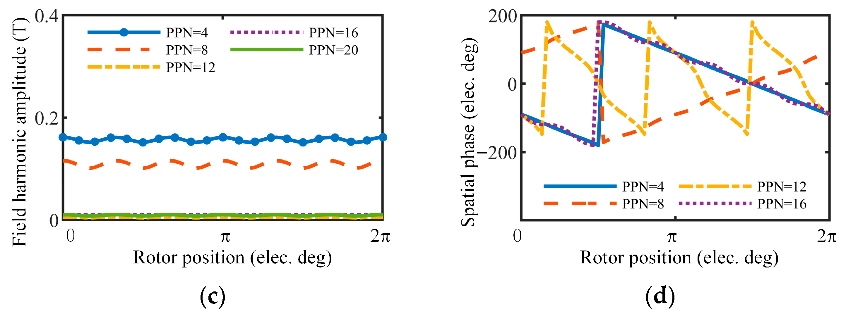
2.5. Modulated PM-Excited and Armature Fields

The modulated PM-excited field can be expressed by multiplying Equations (2) and (4) as
F m ϕ , t = v C m p v sin v p ϕ v p ω t + l v C m s u m v , l sin v p + l N s t ϕ v p ω t + l v C m d i f v , l sin v p l N s t ϕ v p ω t
where C m p , C m s u m , C m d i f represent the coefficient of primitive, summation, and differential modulation processes, respectively, where
C m p v = ε s t 8 π v sin 2 π v ε s t sin π v 2 C m s u m v , l = C m d i f v , l = 2 π v 2 π l sin 2 π l ε s t sin 2 π v ε s t sin π v 2
Similarly, by multiplying Equations (7) and (9), the modulated armature field can be expressed as
F a ϕ , t = δ v C a p v , δ sin v p ϕ ± δ p ω t + δ l v C a s u m v , δ , l sin v p + 2 l p ϕ + ± δ 2 l p ω t + δ l v C a d i f v , δ , l sin v p 2 l p ϕ + ± δ 2 l p ω t
where
C a p v , δ = ε r C a s v , δ C a s u m v , δ , l = C a d i f v , δ , l = C a s v , δ C a r l 2

3. Torque Ripple Analysis

3.1. Three Torque Ripple Components

The virtual work method is an effective way to calculate electromagnetic (EM) torque and reveals the contribution of each field harmonic. Torque ripple can be considered to be caused by the change in magnetic co-energy in the airgap with the rotor position, so that torque ripple can be obtained from the derivation of magnetic co-energy with respect to the rotor position, as expressed by
T = V   w m d V ω t = 1 2 μ 0 V   B 2 d V ω t
where B denotes the flux density, and μ 0 denotes the vacuum permeability.
The total flux density is a combination of PM-excited and armature flux densities, as follows:
B 2 = B m + B a 2 = B m 2 + B a 2 + 2 B m B a
Thus, Equation (12) can be further expressed as
T = 1 2 μ 0 V   B m 2 d V ω t + 1 2 μ 0 V   B a 2 d V ω t + 1 2 μ 0 V   2 B m B a d V ω t
All of the three terms in Equation (14) might generate ripple torque, and thus, they are respectively referred to as PM-excited cogging torque, armature cogging torque, and modulation torque ripple based on their sources. Then, Equation (14) can be expressed as
T r i p p l e = T m c o g + T a c o g + T m o d u
where T r i p p l e , T m c o g , T a c o g , T m o d u denote the total torque ripple, the PM-excited cogging torque, the armature-excited cogging torque, and the modulation torque ripple, respectively.
The third term in Equation (15) is named as the modulation torque ripple because the source of it is related to the modulation behavior, which will be further discussed in the following section.

3.2. Relationship between the Field Harmonics and Torque Ripple

3.2.1. PM-Excited Cogging Torque and Armature Cogging Torque

Take the PM-excited field as an example, according to Equation (10), when the pole pairs of primitive-modulated field harmonic are the same as that of summation-modulated field harmonic as
v p p = v s u m p + l s u m N s t = α
where v p , v s u m represent the rotor modulation order of primitive modulation and summation modulation, respectively. l s u m represents the stator modulation order of summation modulation. α is an odd positive integer.
The synthetic field harmonic can be expressed as
B s = A p sin α ϕ β 1 ω t + A s u m sin α ϕ β 2 ω t
where A p , A s u m represent the amplitude of primitive-modulated and summation-modulated field harmonic, respectively. B s represents the synthetic field harmonic with α pole pairs. β 1 ,   β 2 represent the temporal order of primitive-modulated and summation-modulated field harmonic, respectively.
Equation (17) can be further expressed as
B s = A s sin α ϕ + β 1 β 2 ω t 2 + φ
where A s represents the amplitude of synthetic field harmonic, φ represents the phase shift according to the synthesis, and expressed as
A s = A p 2 + A s u m 2 + 2 A p A s u m cos β 1 + β 2 ω t
tan φ = A p A s u m A p + A s u m tan β 1 + β 2 ω t 2
It can be concluded that the amplitude of the synthetic field harmonic is related to the source field harmonics and ripple when the rotor is rotated.
Substituting Equation (18) into the first term in Equation (14), the PM-excited cogging torque can be expressed as
T m c o g = π R s 2 R r 2 l s t k 4 μ 0 A s ω t
where R s represents the outer radius of the stator. R r represents the inner radius of the rotor.
Clearly, the PM-excited cogging torque is directly related to the amplitude of synthetic field harmonic, as is the armature cogging torque. Hence, the mechanisms of PM-excited cogging torque and armature cogging torque can be revealed as follows: due to the field modulation effect, the pole pairs of the different modulated field harmonics might be the same, but the rotation speed of them is not; this phenomenon results in the amplitude ripple of the synthetic field harmonic and further generates the torque ripple.

3.2.2. Modulation Torque Ripple

Similarly, the modulation torque ripple is related to the modulation effect; the characteristics of the PM-excited field and the armature field are shown in Table 1. When the rotation speeds of PM-excited field and armature field with the same pole pairs are the same, the constant output torque is produced; otherwise, the ripple torque is produced. Since this kind of ripple torque is determined by the modulation difference of the PM-excited field and armature field, it is referred to as the modulation torque ripple.

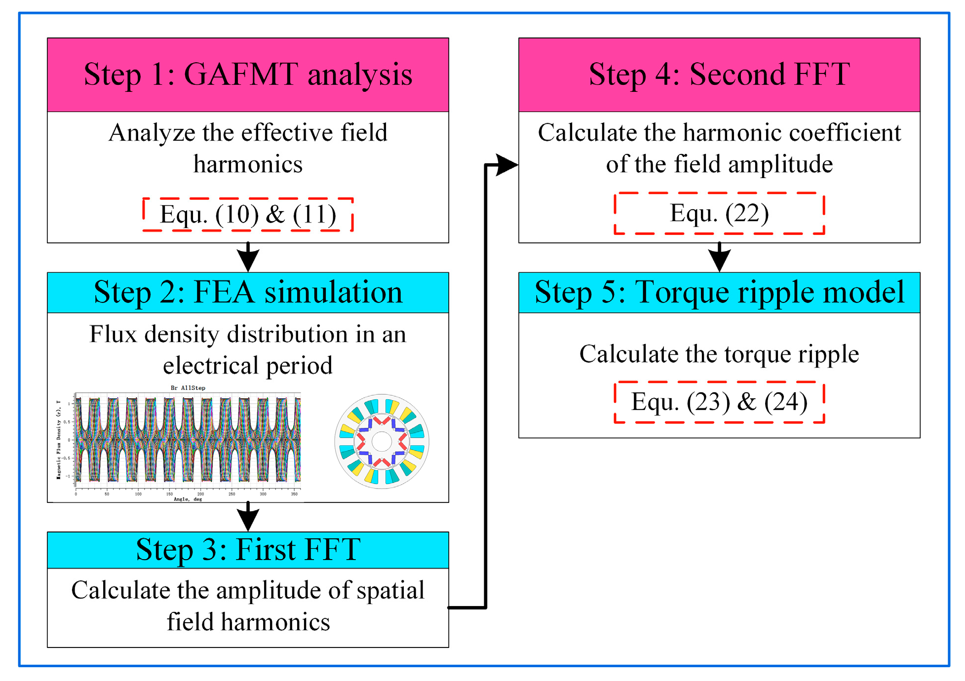
4. FEA-Assisted Dual FFT Analysis Method and Torque Ripple Model

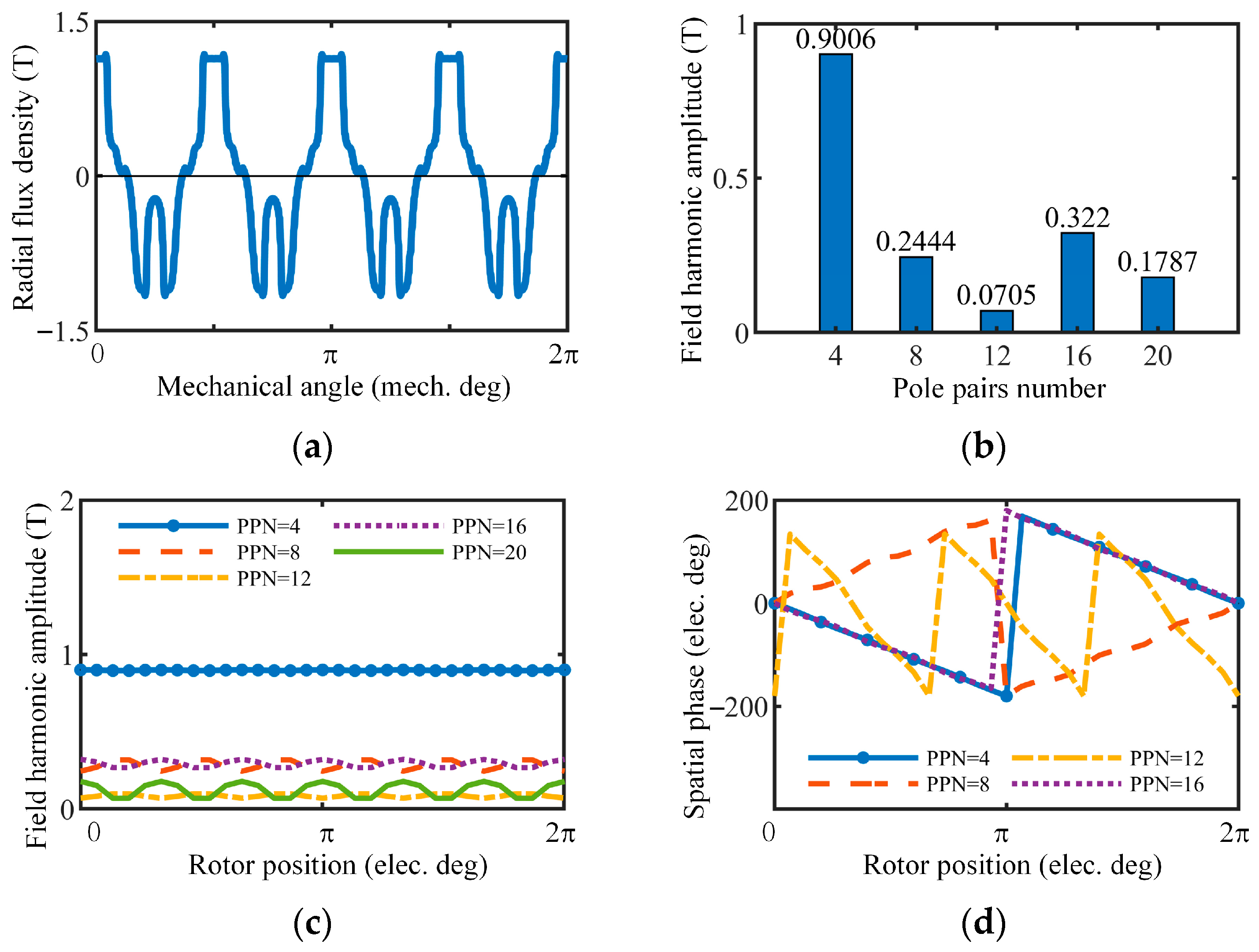
4.1. FEA-Assisted Dual FFT Analysis Method

Based on the above analysis, the key point of calculating the torque ripple is obtaining the amplitude of field harmonics; hence, an FEA-assisted dual FFT analysis method is proposed in this section. This method is based on the GAFMT and assisted by the FEA. In this method, the GAFMT is mainly used in the first spatial FFT decomposition process to quickly select effective field harmonics, while the FEA allows a more precise quantification of the field harmonic amplitude ripple. Compared with the fully GAFMT-based method, the proposed method can save the convolution process while obtaining more accurate ripple values.
The key step of the proposed method is the FEA-based analysis process. The detailed flow chart is shown in Figure 6. Firstly, the effective field harmonics are selected by using the GAFMT in order to exclude invalid field harmonics and save time in the following steps. Then, the FEA simulation is used to obtain the flux density distribution in an electrical period. Furthermore, a first-round FFT analysis is carried out to calculate the amplitude of spatial field harmonics. On this basis, the harmonic coefficient of field amplitudes can be extracted from the second-round FFT analysis. Because the amplitude of field harmonics varies with the rotor position, which is time dependent, it is a function of time, and this process is essentially a temporal FFT decomposition process.
In order to simplify the calculation, only the DC component, first order harmonic, and second order harmonic of the field harmonic amplitude are considered in the analyses. Suppose the amplitude of kth effective field harmonic can be nearly expressed as
A k C k 0 + C k 1 cos γ ω t + φ k 1 + C k 2 cos 2 γ ω t + φ k 2
where A k denotes the field harmonic amplitude. Ck0 denotes the DC component of field harmonic amplitude. C k 1 / φ k 1 and C k 2 / φ k 2 denote the first and second order harmonic amplitudes and phases, respectively, and γ denotes the least common multiple (LCM) of the stator and rotor poles.

4.2. Cogging Torque Model

Substituting Equation (22) into Equation (21), and neglecting the small amplitude components, the cogging torque model can be expressed as
T c o g π R s 2 R r 2 l s t k 4 μ 0 k 2 C k 0 C k 1 γ sin γ ω t + φ k 1 + 8 C k 0 C k 2 γ sin 2 γ ω t + φ k 1

4.3. Modulation Torque Ripple Model

Similarly, to simplify the calculation, only the DC component of field harmonic amplitude is considered in analyzing the modulation torque ripple. Suppose the DC components of the field harmonic amplitude and the temporal orders of the field harmonic with the pole pairs of z are defined as C z m / m and C z a / a , respectively, for the PM-excited and armature fields. Then, the modulation torque ripple can be expressed as
T m o d u π R s 2 R r 2 l s t k 2 μ 0 z C z m C z a m + a p sin m + a p ω t

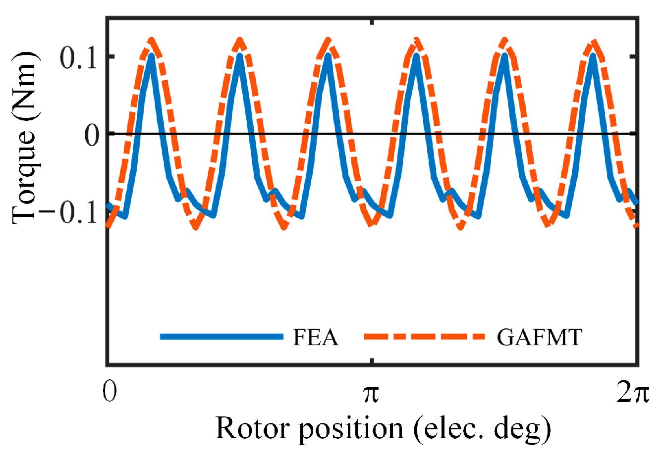
5. Demonstration of Torque Ripple Model

To verify the proposed torque ripple model, FEA-based simulations are carried out. The prototype topology is shown in Figure 7, and the key parameters are given in Table 2.

5.1. PM-Excited Cogging Torque

To verify the PM-excited torque ripple, FEA simulations under no-load condition are carried out. Figure 8 shows the characteristics of the modulated PM-excited field harmonics. Figure 8a,b show the waveform and the spatial spectrum of the PM-excited flux density in the radial direction. It can be seen that there are multiple harmonics in the airgap, where the harmonics with the pole pairs of 4, 12, and 20 are mainly generated by primitive modulation, and those of 8 and 16 are generated by summation and differential modulations. The rotation speed of harmonics with pole pairs of 12 is three times as fast as that of the harmonics with pole pairs of 4, 8, 16. All the above results are consistent with Equation (10).
In conjunction with Figure 8b,c, the harmonic amplitudes with the pole pairs of 16 and 8 may not be equal at a certain time, but their average values are equal in an electrical period. Obviously, this phenomenon demonstrates not only the correctness of GAFMT analysis but also the effect of stator–rotor relative position changes on the field harmonics amplitude.
As shown in Figure 8c, the field harmonics amplitude contains AC components, and the frequency is related to the LCM of the stator and rotor poles. Using the dual FFT method proposed in Section 4, the field harmonics amplitude and the parameters needed in Equation (22) can be obtained. Then, the PM-excited torque ripple can be calculated, as shown in Figure 9.
As shown in Figure 9a, the GAFMT-based PM-excited cogging torque coincides well with the FEA-based result, and the error is mainly due to the neglect of the small value components during calculation. As shown in Figure 9b, even though the torque ripples contributed by harmonics with pole pairs of 20 and 28 are quite high, their phase is 180° apart, so their synthetic torque ripple is considerably reduced, and the same is true for harmonics with pole pairs of 4 and 12.
It is therefore difficult to say that the PM-excited cogging torque is caused by one or several harmonics. With the help of the dual FFT analysis method, it can be seen that the amplitude of all harmonics varies with the rotor position, and they all produce torque ripple. This may mean that the effect of all harmonics on torque ripple should be taken into account when optimizing the machine structure.

5.2. Armature Cogging Torque

The analysis method for armature-excited cogging torque is similar to that of PM-excited cogging torque. One factor that should be noted is that FEA simulations are carried out by using the frozen permeability method to reflect the effect of magnetic bridge saturation. The armature current amplitude is 5 A, and the phase is 0°.
The harmonic with pole pairs of 12 is generated by summation modulation from the harmonic with pole pairs of 4; its rotation speed is three times as fast as that of the harmonic with pole pairs of 4, and its appearance can be explained by the GAFMT, as expressed in Equation (11). FEA simulations also prove this, as shown in Figure 10d.
Similar to the PM-excited field, the amplitude of the armature field harmonics is rippled due to the asynchronous modulation of the rotor salient pole reluctance, as shown in Figure 10c. The field harmonics amplitude is analyzed, and the armature-excited cogging torque is calculated by Equation (20); the results are shown in Figure 11. Compared to other field harmonics, the amplitudes of harmonics with pole pairs of 4 and 8 are high and cause the main armature-excited cogging torque.

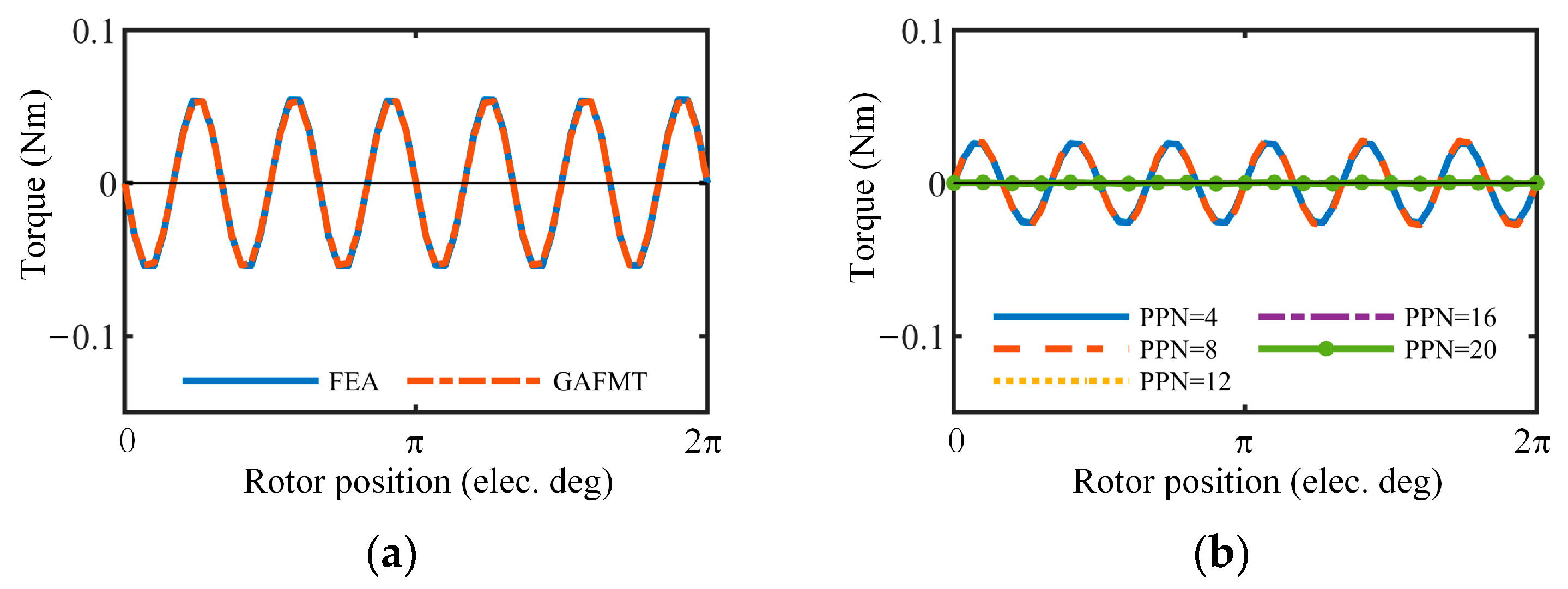
5.3. Modulation Torque Ripple

As analyzed above, the modulation torque ripple is produced by the difference in the rotation speed of the PM-excited field and armature field. For the prototype, the magnetic field distribution and rotation speed are analyzed by GAFMT and given in Table 3.
Substituting the machine parameters into Equations (10) and (11), the rotation speed of PM-excited harmonics with pole pairs of 20 and 28 is 20 ω and 28 ω , respectively, while that of the armature-excited harmonics with the same pole pairs is ±4 ω , respectively. Then, substitute these results into Equation (24). The frequency of modulation torque ripple is 24 ω , which is the same as the PM-excited cogging torque and the armature-excited cogging torque.
The values of C z m and C z a in Equation (24) are also shown in Table 3. The modulation torque ripple curve is shown in Figure 12. Since the higher temporal harmonics are ignored to simplify the calculation, the high-frequency torque ripple of the GAFMT-based result is missing, but overall, the low-frequency value is relatively close, proving the validity of the proposed torque ripple model.

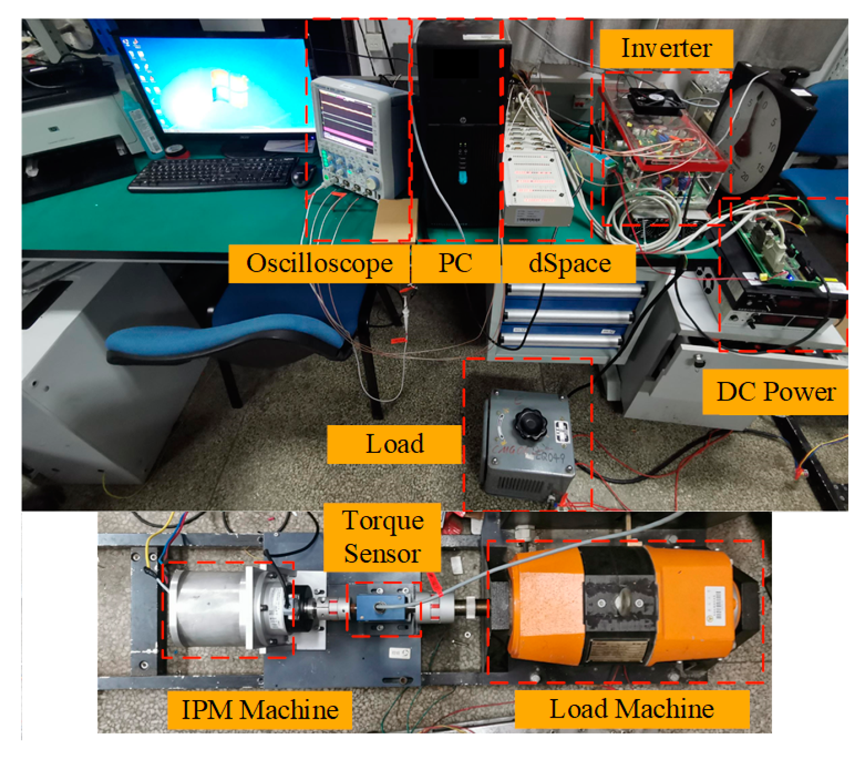
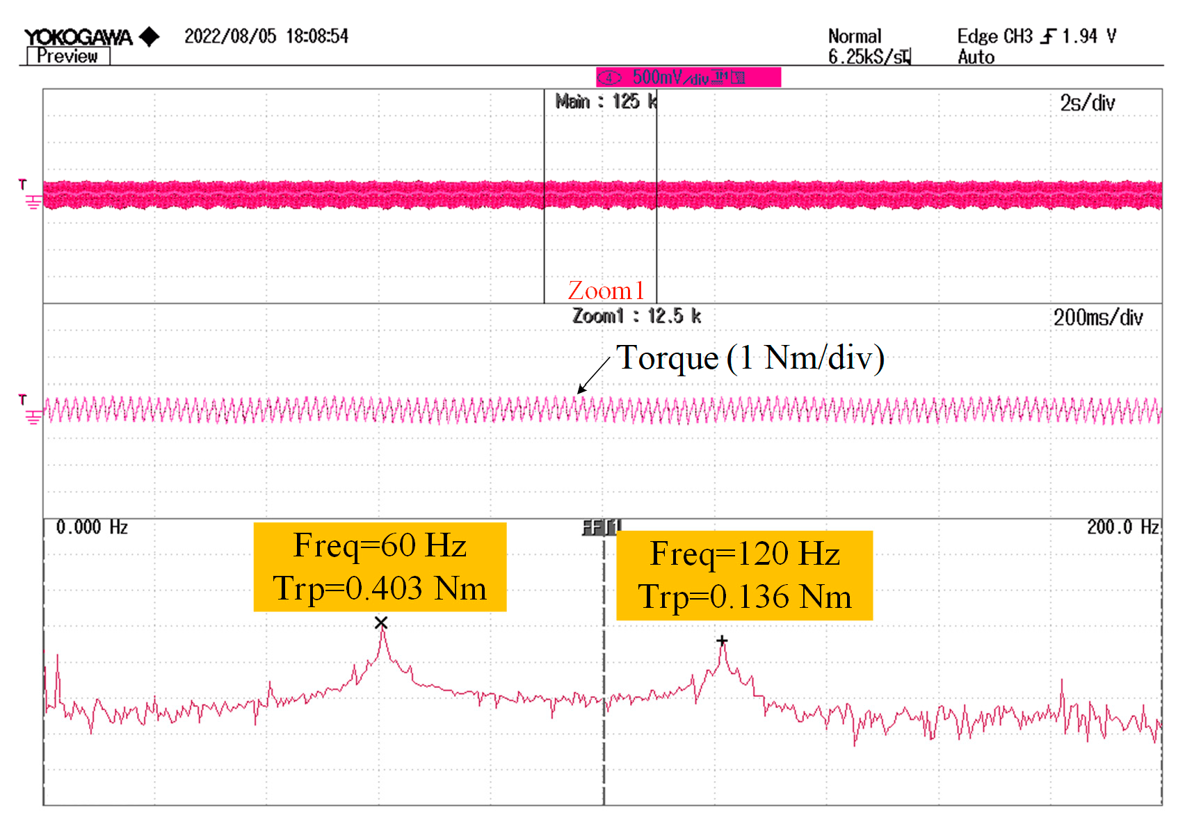
6. Experimental Results

In order to verify the proposed torque ripple model, experiments are carried out. The experimental platform is shown in Figure 13, where the load machine is a brush dc machine, the exciting voltage of which is set as 80 V, and the armature winding is connected to a sliding resistor, as shown in the picture. A high-precision torque sensor is used to measure the torque waveforms, and the dSPACE 1103 platform is used to control the prototype.
Figure 14 is the PM-excited cogging torque measured by the sensor when the IPM machine is rotating at 150 rpm, and the amplitude of the fundamental torque ripple harmonic is 0.403 Nm. This result is in good agreement with the FEA simulation result, which is 0.38 Nm, as shown in Figure 9, and corresponds to the torque ripple model based on the GAFMT.
Figure 15a–c show the torque performance under different rotation speeds while the armature current is set as 1 p.u. (1 p.u. = 3.125 A). According to the proposed model, the torque ripple does not change along with the speed, but as shown in the figures, the torque ripple increases when the speed is 450 rpm. This phenomenon is caused by the low bandwidth of the controller and can be improved by parameter optimization. In order to reduce the influence of the controller parameters on the experimental results, the speed of the subsequent experiments will be set at a low speed.
As discussed in Section 4, the armature current related torque ripple component includes the armature-excited cogging torque and modulation torque ripple; when the amplitude of the armature current increases, these two torque ripples increase. However, all three torque ripple components have the same fundamental frequency; the total torque ripple is not only determined by their amplitude but also influenced by their phase. Figure 15a,d,e show the experimental results when the armature current amplitude is changed, while Figure 15f shows the comparison of the FEA results, the proposed model results, and the experimental results. When the armature current amplitude changes from 0.5 p.u. to 1.5 p.u., the torque ripple decreases from 0.414 Nm to 0.29 Nm in the FEA simulation results, 0.395 Nm to 0.337 Nm in the model results, and 0.428 Nm to 0.334 Nm in experimental results, respectively. It can be concluded that the proposed model can provide a numerically accurate result for the variation of torque ripple with the armature magnetic field, and it confirms the correctness of the three torque ripple components proposed by the GAFMT-based model.

7. Conclusions

In this paper, the spatial characteristics of both PM-excited and armature magnetic field harmonics were first analyzed by using the GAFMT. The influence of the magnetic bridge on the modulation effect was investigated, showing that both the rotor and the stator of the typical V-Shape IPM machine can be considered as the salient pole reluctance.
Then, a novel torque ripple model, which contains three components, is proposed. The total torque ripple is divided into PM-excited cogging torque, armature cogging torque, and modulation torque ripple. Thanks to the general nature of the GAFMT, the proposed model can be extended to any other machine. By subdividing the total torque ripple, it is possible to reveal the mechanisms of torque ripple in different operating conditions and provide guidance for structure or control method-based optimization under full operating conditions.
Furthermore, to achieve an accurate torque ripple model, the FEA-assisted dual FFT method was proposed to investigate the amplitude ripple of the magnetic field harmonics. As the results in the previous sections show, the magnetic field harmonics have, in reality, a significant space–time coupling characteristic and are traveling through waves whose amplitude varies periodically with the relative position between the stator and rotor.
Finally, FEA simulations and experiments were carried out to verify the correctness of the proposed torque ripple model.
On the basis of the proposed method in this paper, the future research is to further explore the potential of the GAFMT, improve the accuracy of the flux density calculation, and reduce the dependence of the model on the FEA results.

Author Contributions

Conceptualization, J.Z.; methodology, J.Z., M.C., W.Y. and W.H.; formal analysis, J.Z. and M.C.; investigation, M.C. and W.H.; writing—original draft preparation, J.Z. and M.C.; supervision, M.C. and W.H.; funding acquisition, M.C. All authors have read and agreed to the published version of the manuscript.

Funding

This research was funded by National Natural Science Foundation of China, grant number 51991381.

Data Availability Statement

Not applicable.

Conflicts of Interest

The authors declare no conflict of interest.

References

  1. Liu, Q.; Hameyer, K. High-performance adaptive torque control for an IPMSM with real-time MTPA operation. IEEE Trans. Energy Convers. 2017, 32, 571–581. [Google Scholar] [CrossRef]
  2. Liu, X.; Chen, H.; Zhao, J.; Belahcen, A. Research on the performances and parameters of interior PMSM used for electric vehicles. IEEE Trans. Ind. Electron. 2016, 63, 3533–3545. [Google Scholar] [CrossRef]
  3. Hao, Y.; Li, J.; Bianchi, F.; Ciuti, G.; Dario, P.; Huang, Q. Analytical magnetic model towards compact design of magnetically-driven capsule robots. IEEE Trans. Med. Rob. Bionics 2020, 2, 188–195. [Google Scholar] [CrossRef]
  4. Zhang, W.; Xu, Y.; Huang, Y.; Zou, J. Reduction of high-frequency vibration noise for dual-branch three-phase permanent magnet synchronous motors. Chin. J. Elect. Eng. 2020, 6, 42–51. [Google Scholar] [CrossRef]
  5. Yamazaki, K.; Utsunomiya, K.; Ohiwa, H. Mechanism of torque ripple generation by time and space harmonic magnetic fields in permanent magnet synchronous motors. IEEE Trans. Ind. Electron. 2022, 69, 9884–9894. [Google Scholar] [CrossRef]
  6. West, H.R. The cross-field theory of alternating-current machines. Trans. AIEE 1926, XLV, 466–474. [Google Scholar]
  7. Fiennes, J. New approach to general theory of electrical machines using magnetic equivalent circuits. Proc. IEE. 1973, 120, 94–104. [Google Scholar] [CrossRef]
  8. Hansen, K.L. The rotating magnetic field theory of AC machines. Trans. AIEE 1925, XLIV, 340–348. [Google Scholar]
  9. Cheng, M.; Han, P.; Hua, W. General airgap field modulation theory for electrical machines. IEEE Trans. Ind. Electron. 2017, 64, 6063–6074. [Google Scholar] [CrossRef]
  10. Cheng, M.; Han, P.; Du, Y.; Wen, H.; Li, X. A tutorial on general air-gap field modulation theory for electrical machines. IEEE J. Emerg. Sel. Topics Power Electron. 2022, 10, 1712–1732. [Google Scholar] [CrossRef]
  11. Cheng, M.; Hua, W.; Zhang, J.; Zhao, W. Overview of stator-permanent magnet brushless machines. IEEE Trans. Ind. Electron. 2011, 58, 5087–5101. [Google Scholar] [CrossRef]
  12. Toba, A.; Lipo, T.A. Novel dual-excitation permanent magnet vernier machine. In Proceedings of the IEEE IAS Annual Meeting, Pheonix, AZ, USA, 3–7 October 1999. [Google Scholar]
  13. Zhu, X.; Hua, W.; Wang, W.; Huang, W. Analysis of back-EMF in flux-reversal permanent magnet machines by air gap field modulation theory. IEEE Trans. Ind. Electron. 2019, 66, 3344–3355. [Google Scholar] [CrossRef]
  14. Wen, H.; Cheng, M. Unified analysis of induction machine and synchronous machine based on the general airgap field modulation theory. IEEE Trans. Ind. Electron. 2019, 66, 9205–9216. [Google Scholar] [CrossRef]
  15. Zhou, J.; Cheng, M.; Wen, H.; Yan, X.; Tong, M.; Wang, W. Modeling and suppression of torque ripple in PMSM based on the general airgap field modulation theory. IEEE Trans. Power Electron. 2022, 37, 12502–12512. [Google Scholar] [CrossRef]
  16. Cheng, M.; Wen, H.; Han, P.; Zhu, X. Analysis of airgap field modulation principle of simple salient poles. IEEE Trans. Ind. Electron. 2019, 66, 2628–2638. [Google Scholar] [CrossRef]
  17. Shin, K.H.; Choi, J.Y.; Cho, H.W. Characteristic analysis of interior permanent magnet synchronous machine with fractional slot concentrated winding considering nonlinear magnetic saturation. IEEE Trans. Appl. Supercond. 2016, 26, 5200404. [Google Scholar] [CrossRef]
  18. Wang, P.; Hua, W.; Zhang, G.; Wang, B.; Cheng, M. Principle of flux-switching permanent magnet machine by magnetic field modulation theory part I: Back-electromotive-force generation. IEEE Trans. Ind. Electron. 2022, 69, 2370–2379. [Google Scholar] [CrossRef]
Figure 1. Rotor modulator structure for PM-excited field.
Energies 16 04586 g001
Figure 2. Distribution of PM-excited field.
Energies 16 04586 g002
Figure 3. Stator modulator for PM-excited field: (a) Structure; (b) Operator function.
Energies 16 04586 g003
Figure 4. Distribution of winding function.
Energies 16 04586 g004
Figure 5. Rotor modulator for Armature field: (a) Structure; (b) Operator function.
Energies 16 04586 g005
Figure 6. Flow chart of the proposed method.
Energies 16 04586 g006
Figure 7. Prototype topology of a 12/8 IPM machine.
Energies 16 04586 g007
Figure 8. Modulated PM-excited field harmonics. (a) Distribution. (b) Spatial spectrum. (c) Harmonic amplitudes in one electrical period. (d) Harmonic phases in one electrical period.
Energies 16 04586 g008
Figure 9. PM-excited cogging torque. (a). Results comparison from GAFMT and FEA. (b). Contributions of different PM-excited field harmonics.
Energies 16 04586 g009
Figure 10. Modulated armature field harmonics. (a) Distribution. (b) Spatial spectrum. (c) Harmonic field amplitude in one electrical period. (d) Harmonic field phase in one electrical period.
Energies 16 04586 g010aEnergies 16 04586 g010b
Figure 11. Armature-excited cogging torque. (a) Comparison of GAFMT result and FEA simulation result. (b) Armature-excited cogging torque produced by different field harmonics.
Energies 16 04586 g011
Figure 12. Modulation torque ripple.
Energies 16 04586 g012
Figure 13. Experimental setup.
Energies 16 04586 g013
Figure 14. PM-excited cogging torque (150 rpm).
Energies 16 04586 g014
Figure 15. Experimental torque performance. (a). 150 rpm, i q = 1 p.u., i d = 0 A. (b). 300 rpm, i q = 1 p.u., i d = 0 A. (c). 450 rpm, i q = 1 p.u., i d = 0 A. (d). 150 rpm, i q = 0.5 p.u., i d = 0 A. (e). 150 rpm, i q = 1.5 p.u., i d = 0 A. (f). Comparison of torque ripple amplitudes under different armature current amplitudes (150 rpm).
Energies 16 04586 g015aEnergies 16 04586 g015b
Table 1. Characteristics of the PM-excited field and the armature field.
ItemPM-Excited FieldArmature Field
Pole PairsRotation SpeedPole PairsRotation Speed
Primitive modulation v p v p ω v p ± δ p ω
Summation modulation v p + l N s t v p ω v p + 2 l p ± δ 2 l p ω
Differential modulation v p l N s t v p ω v p 2 l p ± δ + 2 l p ω
Table 2. The key parameters of the prototype machine.
ParametersValueUnitsParametersValueUnits
Outer diameter of the stator100mmThickness of the PM3.6mm
Inner diameter of the stator59.6mmStack length75mm
Radian of the stator tooth8.1mmNominal torque10Nm
Radian of the stator slot7mmAngle of the V-Shape PMs95deg
Thickness of the magnetic bridge0.7mmOuter diameter of the rotor58.1mm
Table 3. Parameters of PM-excited and armature field.
PM-Excited FieldArmature Field
Pole pairsRotation speedPole pairsRotation speed
20 20 ω 20 4 ω
28 20 ω 28 4 ω
Pole pairs C z m Pole pairs C z a
200.1223200.0093
280.1075280.0266
Disclaimer/Publisher’s Note: The statements, opinions and data contained in all publications are solely those of the individual author(s) and contributor(s) and not of MDPI and/or the editor(s). MDPI and/or the editor(s) disclaim responsibility for any injury to people or property resulting from any ideas, methods, instructions or products referred to in the content.

