Abstract
In this paper, an improved finite control set model predictive current control (FCS-MPCC) is proposed for a two-phase hybrid stepper motor fed by a three-phase voltage source inverter (VSI). The conventional FCS-MPCC selects an optimal voltage vector (VV) from six active and one null VVs by evaluating a simple cost function and then applies the optimal VV directly to the VSI. Though the implementation is simple, it features a large current ripple and total harmonic distortion (THD). The proposed improved FCS-MPCC builds an extended control set consisting of 37 VVs to replace the original control set with only seven VVs. The increase in the amount of VVs helps to regulate the current more accurately. In each control period, the improved FCS-MPCC takes advantage of deadbeat control to calculate a reference VV, and only the three VVs adjacent to the reference VV are predicted and evaluated, which decrease the computational workload significantly. Build waveform patterns for all VVs in the unbalanced circuit structure to modulate the optimal VV using discrete space vector modulation, which improves the current quality in reducing current ripple and THD. The comparative simulations and experimental results validate the effectiveness of the proposed method.
1. Introduction
Hybrid stepper motors (HSM) are widely used in industrial and consumer applications such as textile machines, robotic arms, scanners, printers, etc., due to their low manufacturing cost, high reliability, and open-loop control capabilities [1]. HSMs can operate either in open-loop or closed-loop, and both have similar drive topologies, i.e., each stator winding is driven by an independent H-bridge, H-bridge switches are regulated by a current controller according to the reference current, which is, in turn, generated by a position or speed controller.
Generally, HSMs are operated in the open-loop and have been heavily investigated. The expensive position or speed sensor is no longer needed, which is appealing for industrial and domestic applications [2]. Because the position or speed controller cannot acquire the real position and speed information in real-time, the waveform of reference current needs to be pre-determined. Generally, the maximum current amplitude allowed is chosen to generate maximum torque to avoid step-out. This no-optimal drive method causes low energy efficiency, large torque ripple, and resonance problems [3]. Microstepping has been used to improve the motion stability and positioning resolution, which enables the HSM used in the more demanding applications [4]. However, it is rare to use microstepping in position or speed tracking applications, as microstepping is carried out at a fixed stepping rate. A frequency modulation-based microstepping algorithm is proposed in [5], enabling the microstepping to be used in real-time precise position tracking. However, problems remain, such as step-out due to load torque variation, low energy efficiency, etc.
With the demanding positioning accuracy and the progress of control theory, the position and speed closed loop is broadly used nowadays. Numerous control strategies, such as the conventional proportional integral (PI) [6] and proportional integral derivative (PID) [7], and advanced control strategies, such as fuzzy logic control (FLC) [8], neural network (NN) [9], neuro-fuzzy control (NFC) [10], sliding mode control (SMC) [11], and model predictive control (MPC) [12], are widely used. Generally, a cascade structure is employed, i.e., the outer loop generates reference electromagnetic torque firstly; then, it uses maximum torque per ampere, direct torque control, and field-oriented control (FOC), etc., to modulate a reference current in real-time according to rotor position and speed; finally, the inner current controller regulates stator winding current according to the reference current. In addition, with the continuous improvement of the computing power of microcontrollers, state observer-based sensorless control is a promising method in space or cost restrict occasions, which estimates position and speed information instead of measuring them. A sliding mode observer (SMO)-based sensorless controller is proposed for the speed control of the HSM in [13], where the chattering is solved by embedding FLC into SMO to adjust the observer gain adaptively.
In high-performance applications, no matter what means the position and speed controller adopts, the inner current controller usually uses closed-loop strategies, such as PI [14] and hysteresis control [11]. PI gains widely successful in the application of linear time-invariant systems, but it is difficult to obtain satisfactory results for nonlinear time-varying systems such as stepper motors. Hysteresis control is robust in parameter variations and load torque disturbance, but it results in variable switching frequency, further increasing the switching loss and electromagnetic interference emission [15]. MPC is not a new technology, and it has been in use for decades due to its intuitive concept, simple implementation, straightforward handling of nonlinearities and constraints, and good dynamic performance [16]. In earlier industrial applications, limited by the computing power of the hardware at the time, the implementation of MPC has been restricted to slowly varying process industries. Nowadays, along with the revolutionary development of microprocessor technology, MPC has been implemented successfully in fast-varying systems, such as power converters and drives [17,18,19].
The MPC is classified into finite control set MPC (FCS-MPC) and continuous control set MPC (CCS-MPC) when applied to power converters [20]. CCS-MPC uses a predictive model to compute a continuous control signal and then utilizes a modulator to generate the desired signal to power converters. By taking advantage of the inherent discrete nature of the power converters, FCS-MPC evaluates only a limited number of switching states of the power converter to solve the optimization problem, and then exerts the optimal control action directly to converters [21].
MPC has been successfully applied in induction motors, brushless DC motors, and permanent magnet synchronous motors. Ref. [12] employs two discrete MPCs with the same structure to adjust the direct-axis current and quadrature-axis current under the synchronous d-q frame, respectively. Though CCS-MPC has advantages in long-horizon prediction, its algorithm is complex, and the case of the optimal root exceeding the maximum voltage has not been solved in [12]. Ref. [22] presents a synchronous frame current control strategy for a two-phase linear stepper motor fed by a three-phase VSI. Though they improve the space-vector pulse width modulation (SVPWM) to match the unbalanced circuit structure, the maximum winding voltage is about 70% of the power supply, which is low energy efficiency. In this study, an improved finite control set model predictive current control (FCS-MPCC) is proposed for a two-phase HSM fed by a three-phase VSI.
The main contributions of this paper are as follows:
- (1)
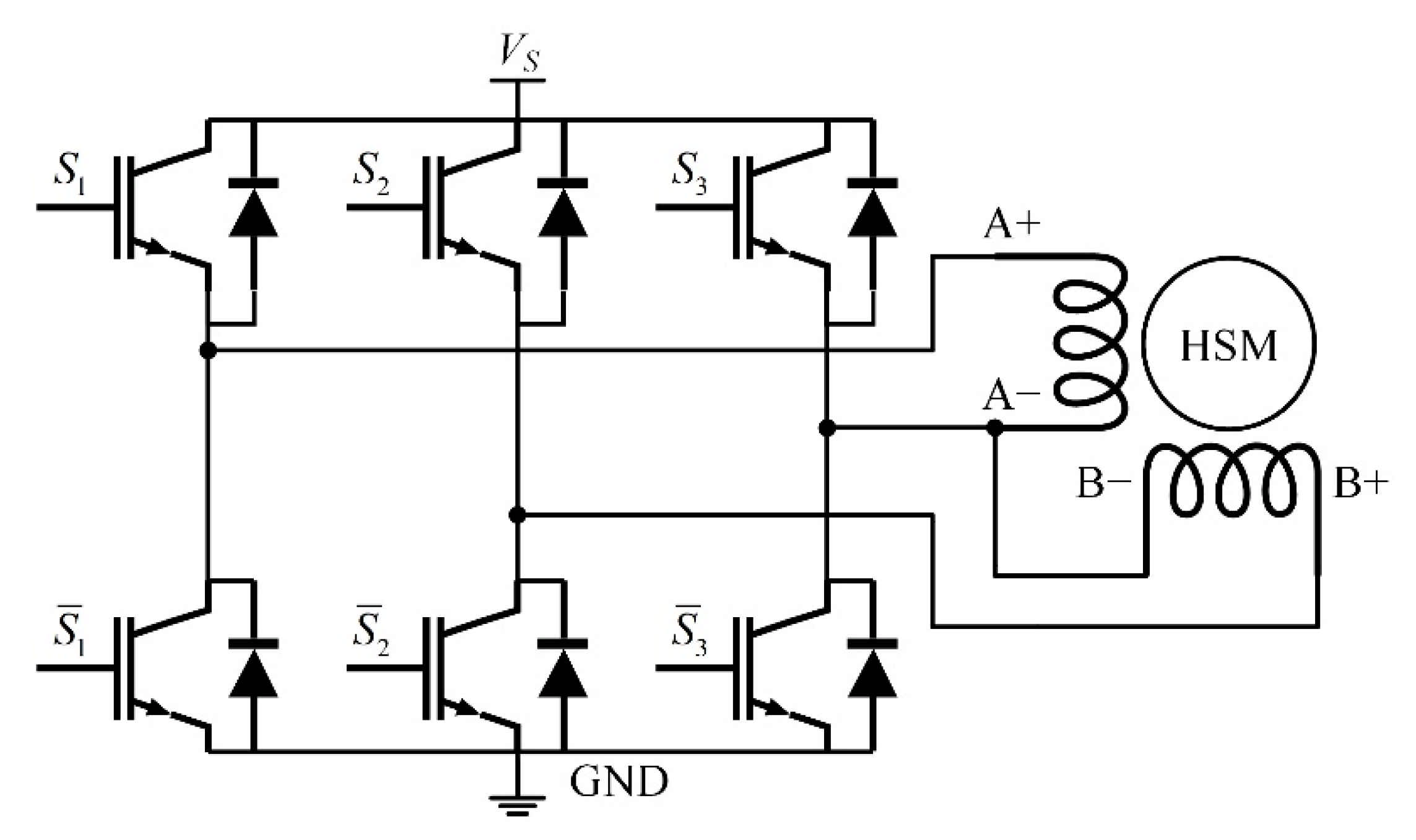
- The two-phase HSM is fed by a low-cost, high-compatibility three-phase two-level VSI, and two-phase currents are regulated simultaneously by an improved FCS-MPCC.
- (2)
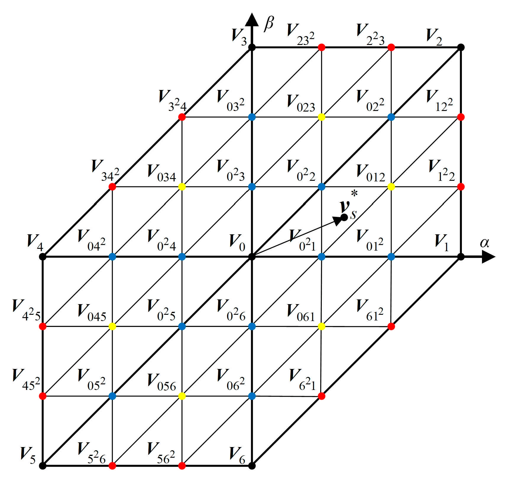
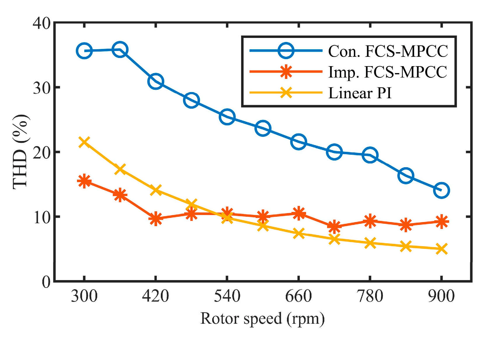
- An extended control set having 37 VVs is built to replace the conventional control set with only six active VVs and one null VVs. The increased VVs improve current quality in rejecting of current ripple and decreasing total harmonic distortion (THD).
- (3)
- Compared with the conventional FCS-MPCC, although the number of admissible VVs in the control set is greatly increased, the workload of determining an optimal VV is significantly reduced. This is because only three VVs adjacent to the reference VV are evaluated in each control period; where the reference VV is obtained using deadbeat control, correspondingly, seven VVs need to be processed in the conventional method.
- (4)
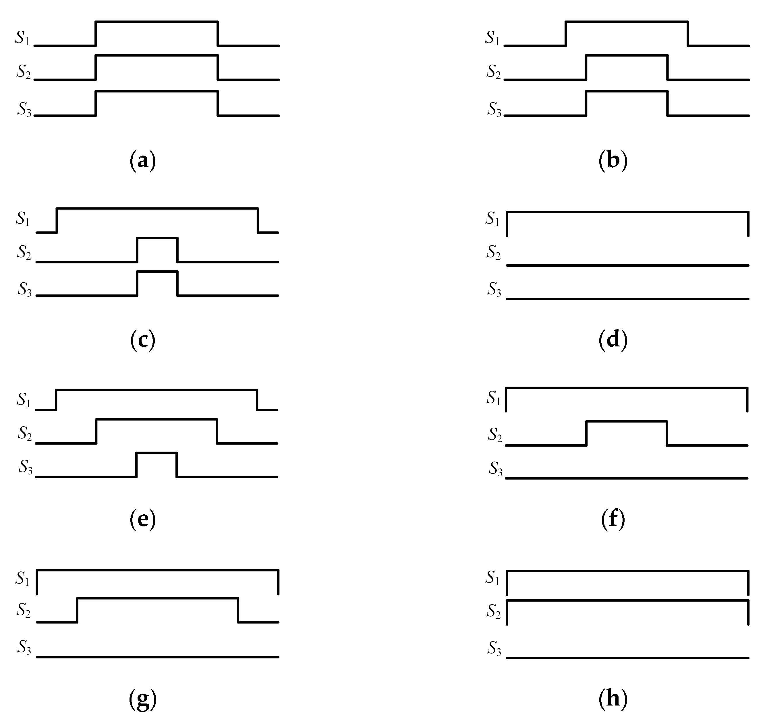
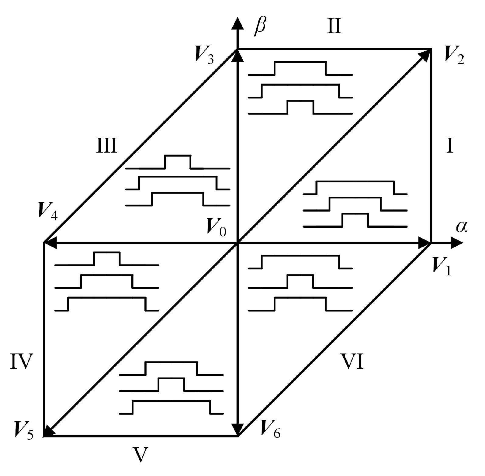
- Build general waveform patterns for each sector, and then instantiate each generalized waveform using corresponding action time to obtain 37 specific waveforms for all VVs. Discrete space vector modulation (DSVM) modulates an optimal VV using the specific waveform related to the VV.
2. Dynamic Model of Two-Phase HSM
The dynamics of the two-phase HSM can be represented in the state-space form [23],
where , and , are the voltages and currents in stator windings A and B, respectively, is the induction of the winding, is the resistance of the winding, is the rotor mechanical (angular) speed, is the rotor mechanical (angular) position, is the inertia of the rotor, is viscous friction coefficient, is the load torque, is the motor torque constant, and is the number of rotor teeth.
The config of the power circuit is shown in Figure 1, a common end formed by connecting the two stator windings A− and B− in series, and the other two open ends of the stator windings A+ and B+ connect to the three legs of VSI, respectively. The upper switches of the three-phase VSI are controlled by , , and , correspondingly, , , and regulate lower switches, and are complementary signals, and x = 1, 2, 3.
Figure 1.
Three-phase VSI fed two-phase HSM.
When , the controlled switch is closed; otherwise, the controlled switch is opened. The three-phase two-level VSI has eight switching state combinations, and each combination generates a VV, i.e.,
where represents a VV, , denotes a switching state, and is the supply voltage. The eight VVs consisting of six active VVs and the other two null VVs. The projection of VVs in the stationary α-β frame forms an asymmetrical hexagon divided equally into six sectors. The active , , …, and are located sequentially at sectors Ⅰ, Ⅱ, …, and Ⅵ, respectively, and the two null and are located at the origin of the hexagon, as shown in Figure 2.
Figure 2.
Six sectors and eight VVs in the stationary α-β frame.
3. The Conventional FCS-MPCC
The FCS-MPCC takes advantage of the feature that VSI has a finite number of switching states to simplify the MPC optimization problem. It consists of predicting currents by enumerating all VVs in the voltage control set, evaluating the prediction currents by a cost function, and directly applying the optimal switching state with the minimum function value to the VSI. Figure 3 illustrates a block diagram of the conventional FCS-MPCC.
Figure 3.
Block diagram of the conventional FCS-MPCC.
3.1. Predictive Model of Current
According to Equation (1), electrical equations of the HSM in α-β frame can be written in the form of complex vectors,
where and are the winding current and voltage vectors, respectively. The values of and are equal to the projection of on the α and β axis. Because predictive currents of the two null VVs are the same, the control set includes the six active VVs and one null . For small sampling times, Equation (3) can be discretized with first-order Euler’s method,
where is the sampling period, and represents the th sampling.
3.2. Cost Function
The cost function is used to evaluate the predicted current, and its form is very flexible. In current control applications, minimizing the current tracking error is the primary goal. Therefore, the cost function includes a current tracking error term, and it has the largest weighting coefficient. Usually, a current limit item that restricts the maximum current flowing through the stator windings is used to improve the safety and stability of the motor. In some applications, it is also critical to limit the switching times of the electronic switch, which is achieved by adding a switching limit item. The general form of a cost function is,
where and are the reference currents of two-phase windings, respectively, and are weighting coefficients of the two limiting items, respectively, is used to limit the maximum current passing through windings, and is used to limit the number of switching times.
FOC is used to modulate reference current; therefore, and are obtained by applying inverse Park transformation to and ,
where is provided by the speed loop, and for simplicity.
The maximum current limit item is defined as
where is the maximum current allowed by the stator winding. The current used in this application is small, and the switching state is optimized in the selection of the optimal VV, ignoring the switching limit term, which is .
In each control cycle, the control algorithm needs to perform current prediction and evaluation operations to all VVs in the control set and select an optimal based on the minimum value principle,
3.3. Compensation for Computation Delay
When implementing a control algorithm on the digital signal processor (DSP)-based platform, the computational time delay problem should not be ignored. It has an adverse influence and will deteriorate the performance of the FCS-MPCC, especially in the case of long predictive horizon control [24]. The time delay problem can be overcome by using a two-step-ahead prediction method [21], i.e., (1) put and into Equation (4) to estimate current at (k + 1)th; (2) predict current of all VVs at (k + 2)th by replacing , which would be measured at (k + 1)th with the estimated current calculated at (k)th. The new prediction equation is obtained by using Equation (4) shifted one step forward in time, i.e.,
The cost function needs to be redefined, i.e., the optimal VV forces to trace at the th instant [25].
At last, the optimal switching state is applied to three-phase VSI directly, avoiding using a modulator. Though a simple structure, the electronic switching frequency is not constant, which leads to spread harmonic spectra of the output signal [26]. Furthermore, current ripple and THD is high due to only one VV is applied to the VSI in a control period.
4. The Improved FCS-MPCC
To improve the current quality of the conventional FCS-MPCC, an extended control set having 37 VVs is constructed to replace the original control set having only six active and one null VVs. The new VV, also called virtual or synthesized VV, is implemented using DSVM.
4.1. Virtual VV Syntheses by DSVM
According to the working principle of DSVM, firstly, a whole control period is divided into several parts. Then, a virtual VV is synthesized by applying original VVs to the VSI sequentially in a whole control period. Assuming is subdivided into parts equally, the virtual VV can be expressed as follows:
where
The total number , including real and virtual VVs, is
In this design, N = 3, and therefore, Nc = 37. All VVs are shown in Figure 4 and are distinguished by a colored dot: black dots represent the original seven VVs; red, yellow, and blue dots indicate virtual VVs, which are synthesized by two active VVs, two active VVs and , and one active VV and , respectively. The superscript and subscript of the VV detail the synthesis information. For example, is synthesized by and , and action times are and , respectively; correspondingly, is synthesized by , , and , and action times are all .
Figure 4.
Real and virtual VVs in α-β frame.
The increased VVs contribute to improving the current quality. However, it is difficult to evaluate all VVs in one control period under the current computation power of the DSP. A natural idea is to exclude some unnecessary VVs to decrease the computation time. Usually, a direct or indirect reference VV is pre-computed, and then these VVs located near the reference VV are selected into a new control set. The optimization algorithm evaluates VVs in the new control set only [27]. Deadbeat predictive control is one of the most effective methods to compute the direct reference VV and is detailed in the following section.
4.2. Computational Cost Reduction by Deadbeat Control
Deadbeat control is a branch of predictive control, and it is employed broadly in motor drives. It is classified into deadbeat predictive torque and flux control and deadbeat predictive current control (DPCC). The principle of DPCC is to calculate a manipulated input to force the current to reach its reference value after one sampling period [28]. Assuming , according to the discretized Equation (4), the manipulated input is,
The computational time delay also exists in the implementation of DPCC. Usually, a one-step-ahead prediction method is used, i.e., a manipulated VV , obtained at the kth instant, is modulated at the (k + 1)th instant. The manipulated VV is obtained using Equation (13) shifted one step forward in time,
Only the three VVs adjacent to are manipulated by the control algorithm. As shown in Figure 4, assuming is a reference VV obtained by DPCC, , , and , adjacent to , need to be manipulated. In a word, the amount of VVs of the conventional and improved FCS-MPCC are 7 and 37, respectively. However, the number of VVs that need to be predicted and evaluated for the two methods are seven and three, respectively. Therefore, the computation time for the optimization algorithm of the improved FCS-MPCC does not increase with the increased VVs.
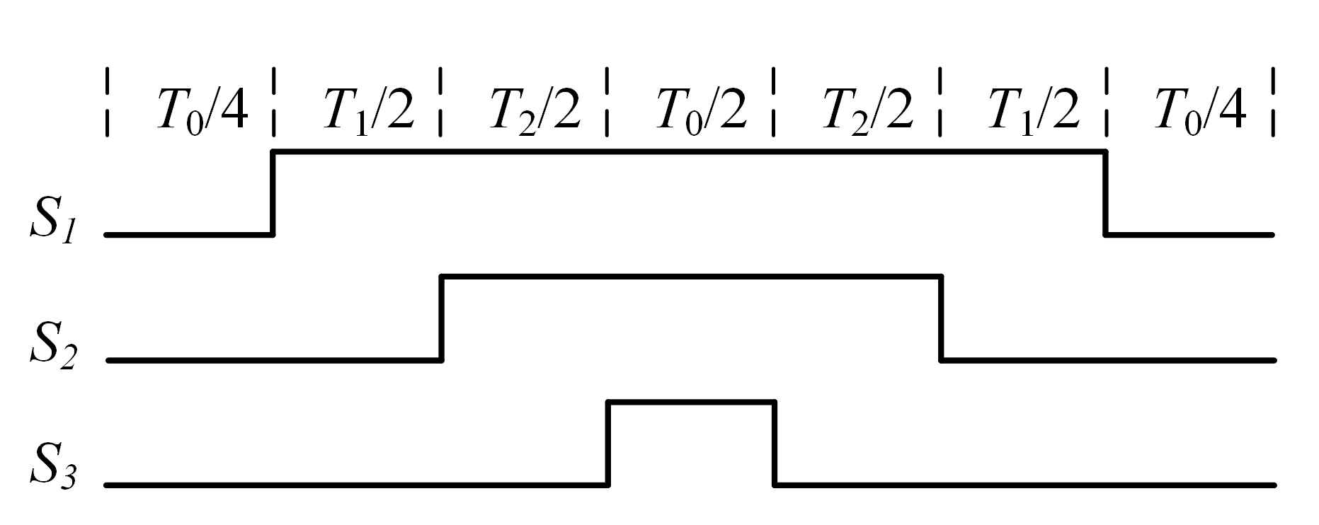
4.3. Switching State Generation
The improved FCS-MPCC utilizes DSVM to modulate optimal VV, which is a distinct difference from conventional FCS-MPCC. As the general SVPWM cannot be applied directly in an unbalanced circuit structure, we build new waveforms for each VV. As waveform patterns of the six sectors have strong similarities, we detail the waveforms of all the VVs in sector Ⅰ. These virtual VVs, , , , , and , are synthesized by , , and , and discrete Equation (10) is further simplified,
where the action times , , and are taken from , , , and . Table 1 details the action time for each virtual VV and original VVs , , and .
Table 1.
Detailed action times for all VVs in sector Ⅰ.
Proper action orders also play an important role, as different action orders result in different waveform patterns. In this design, the action orders can approximately output constant switching frequency, which improves the harmonic spectra of the current waveforms. Figure 5 illustrates a generalized waveform pattern in a PWM period of sector Ⅰ, including action order, duty cycle, and switching scheme. It has the following properties:
Figure 5.
Generalized waveform pattern for VVs in sector Ⅰ.
- (1)
- The noninverted control signals for , , and are symmetrical to the middle of the PWM period. This is because the symmetrical waveforms are easy to be realized in DSP; furthermore, additional harmonics exist around the switching frequency when the asymmetry waveforms are used.
- (2)
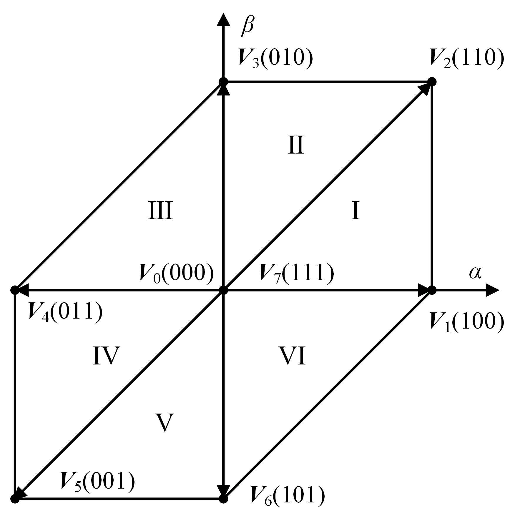
- The switching orders are S000-S100-S110-S111-S110-S100-S000, where numeral subscripts represent the switching states of the noninverted control signal S1, S2, and S3. Correspondingly, VSI generates V0-V1-V2-V7-V2-V1-V0 sequentially, which is identical to the general SVPWM.
- (3)
- Each control period starts and ends with S000, and S111 is inserted into the control period. Therefore, each noninverted control signal switches twice per PWM period except when the duty cycle is 0% or 100%, which can assure the control signal switching at constant frequency except for the cases in which the duty cycle is 0% or 100%.
The specific waveform of each VV in the sector Ⅰ is obtained by instantiating the generalized waveform pattern using corresponding action time. Virtual and are synthesized by and , where the only difference between them lies in the action time for and . Therefore, they share the most similar waveform patterns, as shown in Figure 6b,c, respectively. , , and using the same action time, , synthesize , as shown in Figure 6e. Virtual and are synthesized by and only, so is zero, and their waveforms are shown in Figure 6f,g, respectively. The real , , and are also generated by DSVM, and waveforms are illustrated in Figure 6a,d,h, respectively.
Figure 6.
Instantiated waveform patterns for each VV in sector Ⅰ. (a) ; (b) ; (c) ; (d) ; (e) ; (f) ; (g) ; (h) .
Generalized waveform patterns for other sectors are obtained employing similar method used in sector Ⅰ. The six generalized waveforms located at the corresponding sectors of the asymmetrical hexagon are illustrated in Figure 7. As can be seen, they share some features, e.g., fixed switching orders among control signals for each sector, etc.
Figure 7.
Generalized waveform patterns in all six sectors.
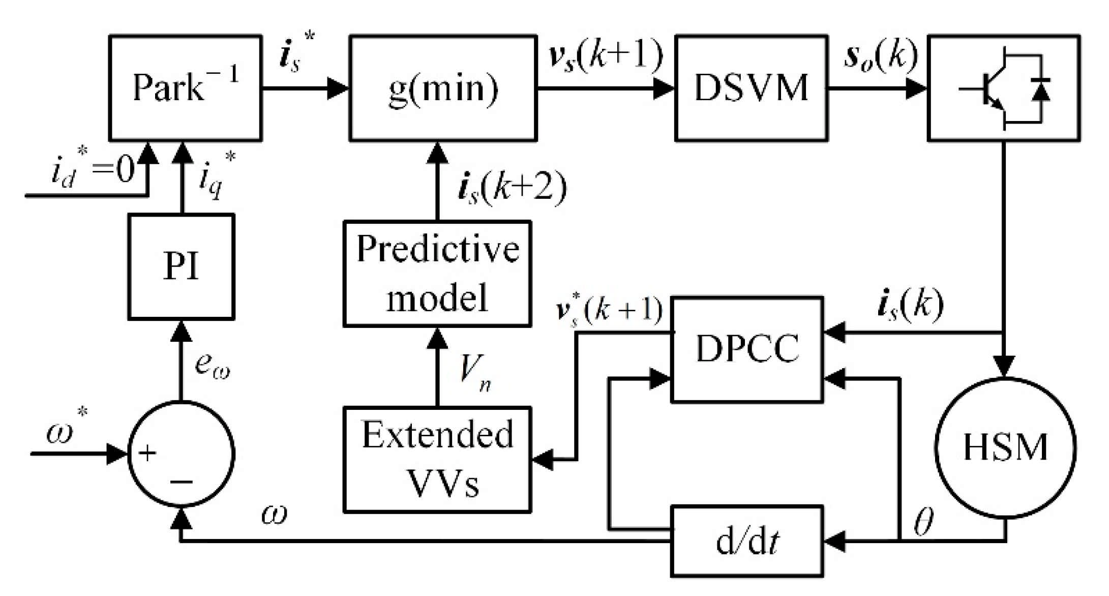
4.4. Overall Improved FCS-MPCC Scheme
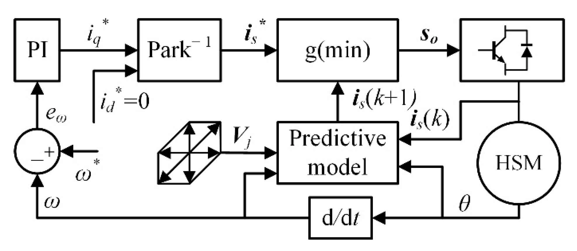
The block diagram of the proposed improved FCS-MPCC is shown in Figure 8, and the whole control procedures are summarized as follows:
Figure 8.
Block diagram of the improved FCS-MPCC.
- (1)
- Measure current , rotor mechanical position , and speed at the th instant.
- (2)
- Modulate the optimal VV using DSVM, where was obtained at the (k − 1)th sampling period.
- (3)
- Estimate current , taking advantage of , , and , etc.
- (4)
- Predict a reference VV using DPCC, and then build a new control set , consisting of only three VVs adjacent to .
- (5)
- Predict current for each VV in , and then evaluate them using a cost function; finally, determine the optimal VV based on the minimum value principle.
5. Simulation and Experimental Verification
In this design, a speed regulator is built using MATLAB/Simulink to evaluate the performance of HSM using different current regulation strategies. It adopts cascade control, where the outer speed loop uses PI, and the inner current loop utilizes (1) conventional FCS-MPCC, (2) improved FCS-MPCC, and (3) traditional dual H-bridges PI, respectively. The conventional FCS-MPCC has been implemented as a benchmark method. Key parameters of the two-phase HSM are listed in Table 2, the sampling frequency is 40 kHz, gains of speed PI controllers are and , and gains of current PI controller are and . These PI gains are obtained using the Ziegler–Nichols tuning method and validated using MathWorks script command.
Table 2.
Key specifications of the two-phase HSM.
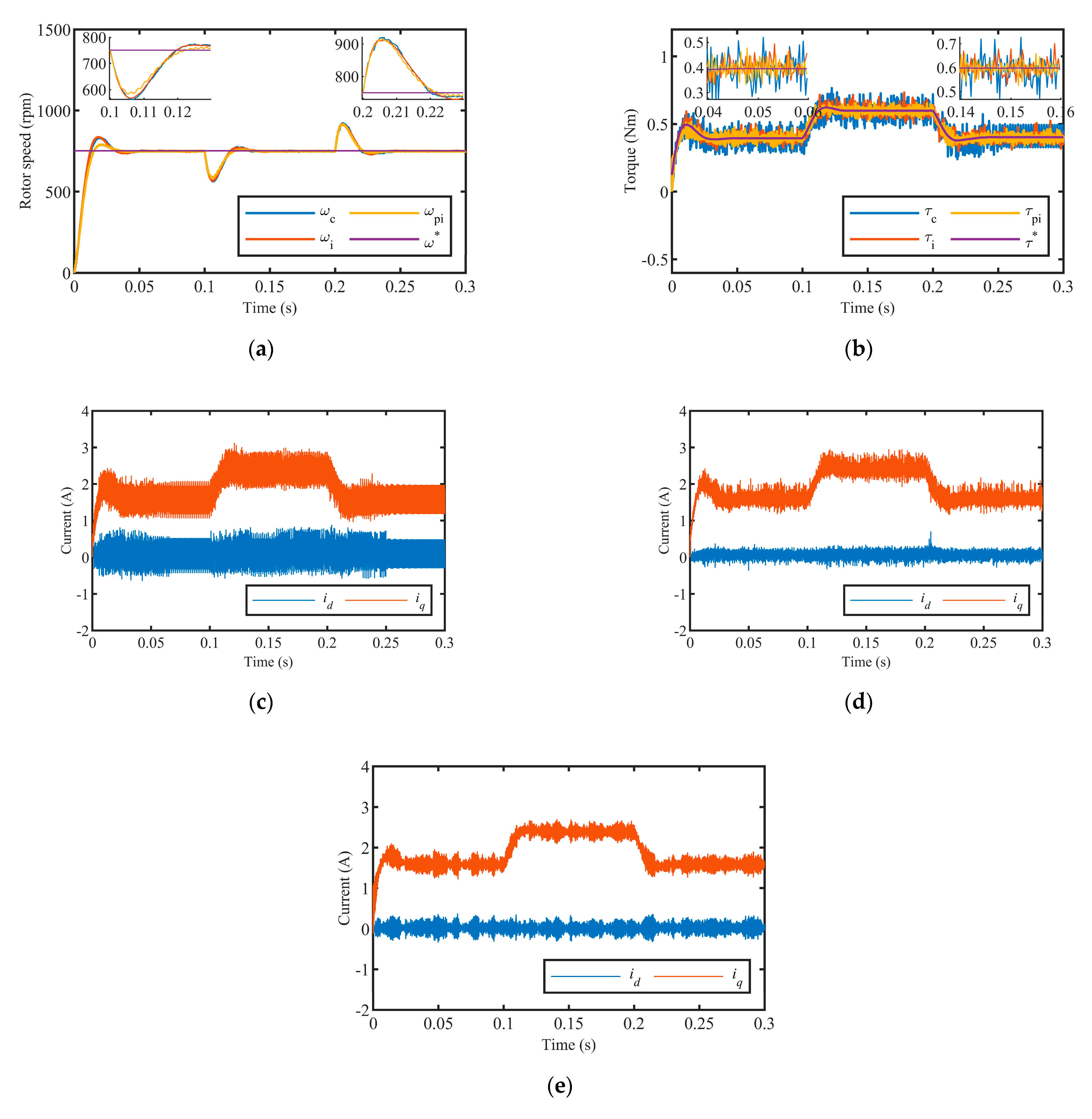
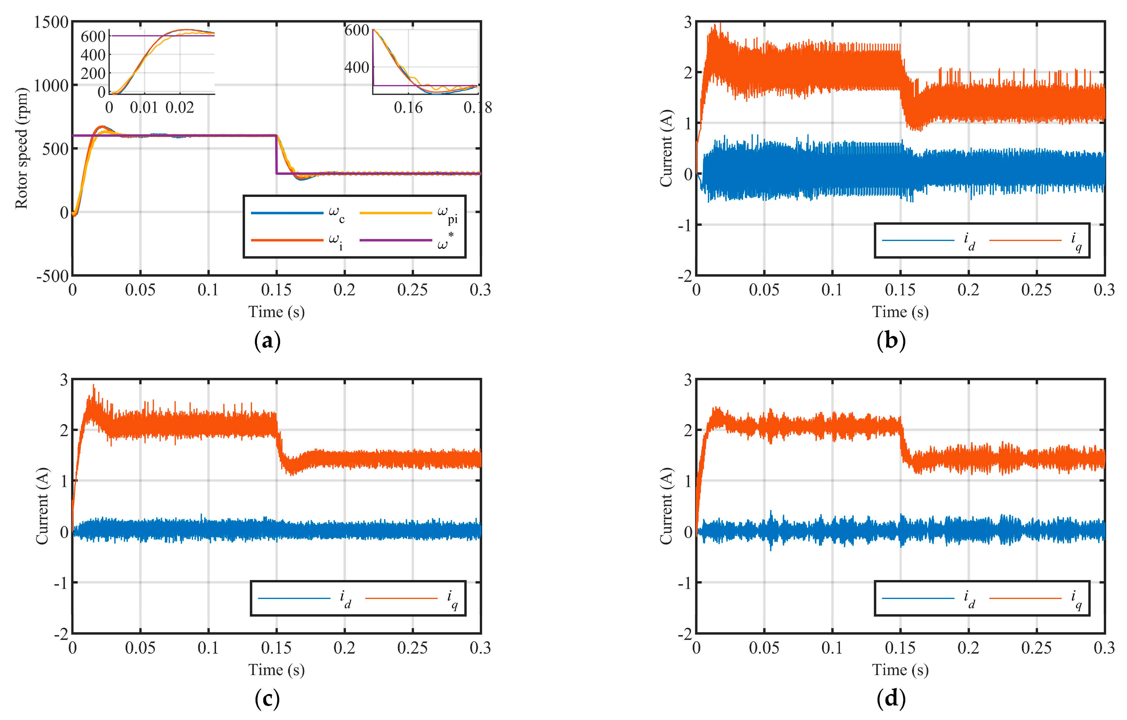
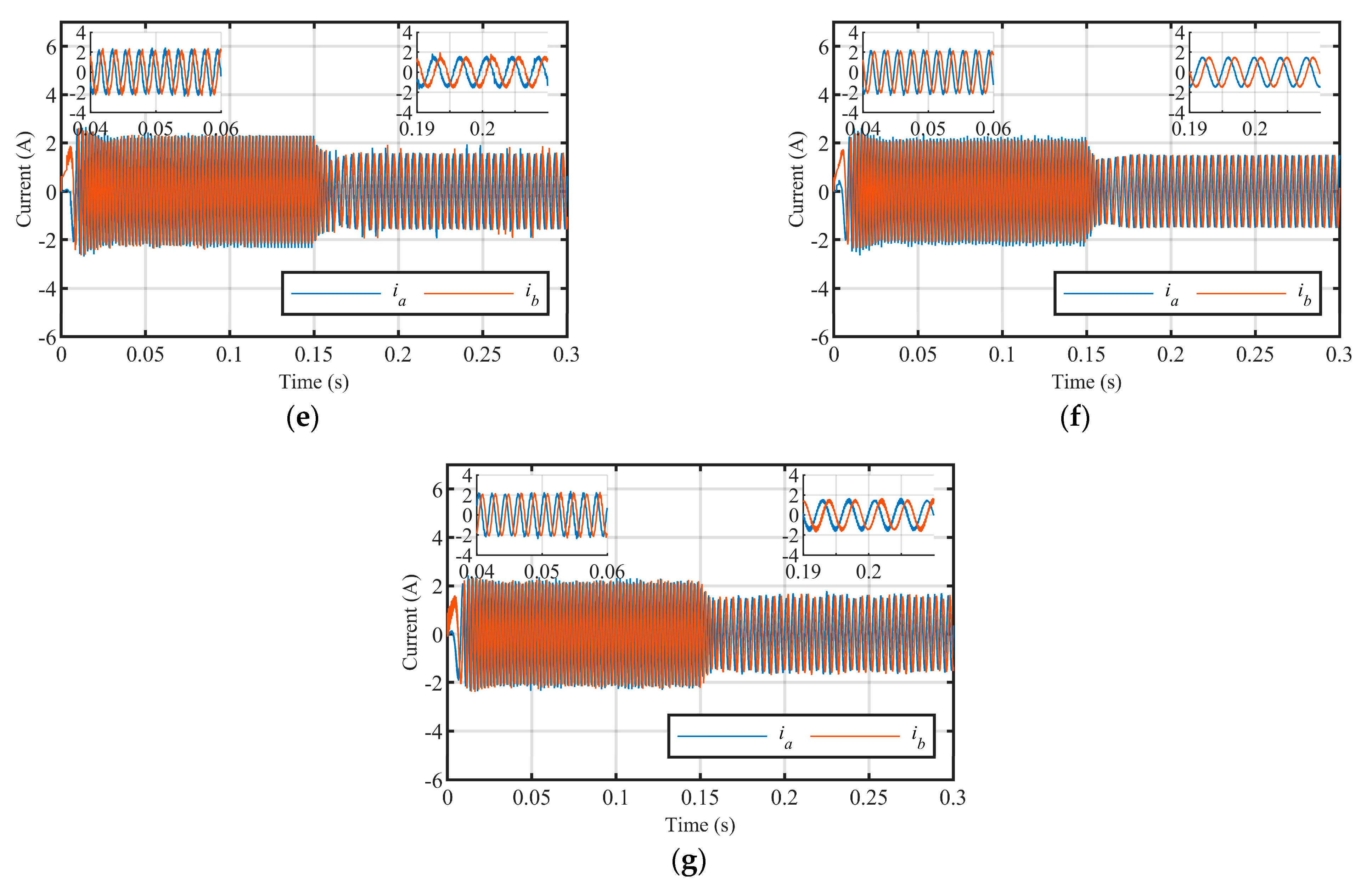
5.1. Simulation Verification
In the following simulations and experiments, the rotor speed obtained using the conventional FCS-MPCC, the improved FCS-MPCC, and the linear PI are represented by , , and , respectively. Correspondingly, , , and represent the torque obtained by these methods, respectively. The first simulation evaluates the transient and steady-state performance of the system without load torque disturbance. The reference speed steps to 240, 720, and 240 rpm at 0.0, 0.1, and 0.2 s, respectively, from standstill. For all methods, real speed tracks well, setting time is about 0.03 s, and there is no steady-state error, as shown in Figure 9a. The torque response is shown in Figure 9b, where the reference torque is modulated by the speed PI controller, and the significant torque ripple is observed in the conventional FCS-MPCC.
Figure 9.
Speed, torque, and current responses of the HSM without load torque disturbance. (a) Speed response; (b) torque response; (c) current response of conventional FCS-MPCC in α-β frame; (d) current response of improved FCS-MPCC in α-β frame; (e) current response of dual H-bridges PI in α-β frame.
Current responses are illustrated in Figure 9c–e. For all methods, waveforms vary in a sinusoidal fashion, where the amplitude is proportional to rotor mechanical speed, and the frequency equals the product of the rotor angular frequency and the number of teeth on the rotor. However, there are distinct differences in the aspect of current quality, such as the current ripple.
The current ripple of conventional FCS-MPCC is the largest, as shown in Figure 9c. The reason for this is that the amount of effective VVs is not enough to accurately control current, and a larger current ripple inevitably occurs. As for the improved FCS-MPCC, the number of effective VVs is significantly increased, the current control is more accurate, and it has better current quality, as shown in Figure 9d.
A larger current ripple also exists in the traditional PI, as shown in Figure 9e. The PI controller regulates the current by controlling the duty cycle of the two-level PWM. The H-bridge will not work in freewheeling mode, and the current ripple is , while it is only when the three-level PWM is used. A mixed-mode PWM for high performance HSM applications is proposed in [29], which makes a hybrid of the two-level and three-level PWM strategies to reduce current ripple, but it is difficult to implement the algorithm.
The second simulation evaluates the transient and steady-state performance of the system under load torque disturbance when HSM runs at high speed. The reference speed steps to 750 rpm at instant 0 s without load torque disturbance, and then a 0.2 Nm disturbance is applied to the system at 0.1–0.2 s.
All methods present excellent speed tracking abilities, as shown in Figure 10a. Firstly, the rotor accelerates to 750 rpm and runs steadily until a disturbance is being exerted to the system. Then, the speed descends instantly to about 563.2, 568.8, and 591.1 rpm, respectively, is restored to 750 rpm in about 0.03 s, and then runs steadily until the disturbance is being released. When the disturbance is removed, the speed ascends instantly to about 919, 912.1, and 910.5 rpm, respectively, is restored to 750 rpm in about 0.03 s, and then runs steadily.
Figure 10.
Speed, torque, and current response of the HSM with load torque disturbance. (a) Speed response; (b) torque response; (c) current response of conventional FCS-MPCC in d-q frame; (d) current response of improved FCS-MPCC in d-q frame; (e) current response of dual H-ridges PI in d-q frame.
The torque response is shown in Figure 10b. As can be seen, increases to 0.59 Nm from 0.39 Nm when the load torque is being applied, and torque ripple exists for all three methods, where the conventional FCS-MPCC has the largest torque ripple. As is known, the instantaneous torque is composed of electromagnetic torque and reluctance torque [29]. The instantaneous torque is further simplified to by keeping and ignoring detent torque . As a result, the torque and speed responses are determined by the quality of the current, i.e., the improved current quality contributes to reducing torque and speed ripple.
The current responses in d-q frame are illustrated in Figure 10c–e. For all three methods, pulsates at 0 A, where the conventional FCS-MPCC has the largest pulsation amplitude, about 0.5 A, and the other two have approximately identical pulsation amplitude, i.e., 0.3 A. The quadrature current component varies according to , and its average value increases to 2.32 A from 1.59 A when the load torque is being applied. Ripple also exists in , where conventional FCS-MPCC has the largest pulsation amplitude, and the other two have approximately identical pulsation amplitudes.
The superiority of the proposed method is not only reflected in its high current tracking capability and low current ripple, but also in smaller THD. To further compare the performance, the current THD of all methods obtained at various speeds without load torque disturbance is shown in Figure 11. By investigating simulation data, three important conclusions have been obtained: (1) the THD of the improved FCS-MPCC is smaller than the THD of the conventional FCS-MPCC in the whole speed ranges, and huge differences exist at low-speed ranges; (2) compared with the traditional dual H-bridges PI method, the THD of the improved FCS-MPCC is slightly higher, which is mainly caused by the unbalanced circuit structure; (3) the THD of the improved FCS-MPCC fluctuates at 10.0 when the rotor speed is higher than 420 rpm, so its THD is approximately independent of the speed.
Figure 11.
THD comparison at various speeds for all methods.
5.2. Experimental Verification
Experiments were carried out on a front-leg mechanism of a stairs-climbing wheelchair robot. The experimental setup is composed of HSM, motor drive, main controller, a front-leg of wheelchair robot with a multi-stage gear reducer, etc., as shown in Figure 12. The main controller plans the movement of the front-leg mechanism, and HSM is the actuator to lift the front leg. The parameters of HSM and motor drive are identical to the MATLAB simulation, and TMS320F28035 is used in both motor drive and main controller.
Figure 12.
Experimental setup.
The experiment verifies the performance of using a multi-step speed strategy to drive the front-leg to complete lifting motion. The reference speed steps to 600 and 300 rpm at 0 and 0.15 s, and conventional FCS-MPCC, improved FCS-MPCC, and dual H-bridges PI are used to regulate current, respectively. The speed response is shown in Figure 13a, where the setting time is about 0.03 s, and there is no steady-state error, which is consistent with simulations.

Figure 13.
Speed and current responses of HSM under load. (a) Speed response; (b) current response of conventional FCS-MPCC in d-q frame; (c) current response of improved FCS-MPCC in d-q frame; (d) current response of the dual H-bridges PI in d-q frame; (e) current response of conventional FCS-MPCC in α-β frame; (f) Current response of improved FCS-MPCC in α-β frame; (g) current response of the dual H-bridges PI in α-β frame.
As mentioned above, the quadrature component illustrates the torque response effectively. In the d-q frame, current responses obtained by the three control strategies above are shown in Figure 13b–d, respectively. The direct axis component pulsates at 0 A for all the methods, where conventional FCS-MPCC has the largest ripple, about 0.6 A; correspondingly, the ripple of the other two methods is almost the same, about 0.2 A. The quadrature component varies according to , and its value descends to 1.4 A from 2.0 A when steps to 300 rpm from 600 rpm. The ripple also exists in , and conventional FCS-MPCC has the largest ripple, about 0.6 A; correspondingly, the ripple of the other two methods is about 0.2 A. Although the maximum ripple of the two strategies is almost the same, the curve of the improved FCS-MPCC is much smoother; therefore, it is more robust to load disturbance.
In the α-β frame, current responses obtained by the three control strategies above are shown in Figure 13e–g, respectively. For all methods, the current varies in sinusoidal fashion, where the amplitude and frequency are 2.1 A and 1.5 A and 500 Hz and 250 Hz, respectively, when are 600 and 300 rpm. Furthermore, the minimum ripple can be observed in the improved FCS-MPCC, which contributes to improving current quality and decreasing THD.
6. Conclusions
In this paper, an improved FCS-MPCC is proposed for a two-phase HSM fed by a three-phase VSI. It is a hybrid control strategy that integrates the advantages of both FCS-MPCC and CCS-MPCC. On the one hand, the optimal VV is selected based on FCS-MPCC, inheriting the advantages of intuitive concept and simple implementation. On the other hand, the optimal VV is modulated using DSVM, being similar to CCS-MPCC, which has advantages of high current quality and low THD. The proposed method mainly consists of (1) building an extended control set that includes 37 VVs to replace the original control set with only seven VVs; (2) decreasing computational time for the optimization algorithm, using DPCC to obtain a reference current, where only the three VVs adjacent to the reference VV are evaluated in each control period; and (3) modulating the optimal VV using DSVM. In summary, the amount of VVs in the control set of the improved FCS-MPCC is 5.29 times of the conventional FCS-MPCC, but the amount of VVs required for current prediction and evaluation per control cycle is 0.43 times the conventional method; the only cost is that the microprocessor must provide a modulator module. Its superiorities have been confirmed through comparative simulations and experimental tests, the results of which show that: (1) compared with the conventional FCS-MPCC, it not only significantly improves the current quality but also reduce the computational workload, which enables it to be running in an economical processor; and (2) compared with the traditional dual H-bridges PI strategy, it has approximately identical performance indices, but it benefits in simple hardware structure, low cost, fast dynamic response, and strong robustness to load disturbances, etc.
Author Contributions
Conceptualization, C.W.; methodology, C.W.; formal analysis, X.Q. and D.C.; writing—original draft preparation, C.W.; writing—review and editing, C.W. and D.C.; project administration, C.F.; funding acquisition, D.C. All authors have read and agreed to the published version of the manuscript.
Funding
This research was funded by National Natural Science Foundation of China (No. 51875167) and Natural Science Foundation of Hebei Province in China (E2018202114).
Institutional Review Board Statement
Not applicable.
Informed Consent Statement
Not applicable.
Data Availability Statement
Not applicable.
Conflicts of Interest
The authors declare no conflict of interest.
References
- Zaky, M.S. A self-tuning PI controller for the speed control of electrical motor drives. Electr. Power Syst. Res. 2015, 119, 293–303. [Google Scholar] [CrossRef]
- Derammelaere, S.; Vervisch, B.; De Viaene, J.; Stockman, K. Sensorless load angle control for two-phase hybrid stepper motors. Mechatronics 2017, 43, 6–17. [Google Scholar] [CrossRef]
- Derammelaere, S.; Vervisch, B.; Belie, F.D.; Vanwalleghem, B.; Cottyn, J.; Cox, P.; Abeele, G.V.d.; Stockman, K.; Vandevelde, L. The Efficiency of Hybrid Stepping Motors: Analyzing the Impact of Control Algorithms. IEEE Ind. Appl. Mag. 2014, 20, 50–60. [Google Scholar] [CrossRef]
- Kim, W.; Shin, D.; Lee, Y.; Chung, C.C. Simplified torque modulated microstepping for position control of permanent magnet stepper motors. Mechatronics 2016, 35, 162–172. [Google Scholar] [CrossRef]
- Gaan, D.R.; Kumar, M.; Sudhakar, S. Real-Time Precise Position Tracking with Stepper Motor Using Frequency Modulation Based Microstepping. IEEE Trans. Ind. Appl. 2018, 54, 693–701. [Google Scholar] [CrossRef]
- Le, K.M.; Hoang, H.V.; Jeon, J.W. An Advanced Closed-Loop Control to Improve the Performance of Hybrid Stepper Motors. IEEE Trans. Power Electron. 2017, 32, 7244–7255. [Google Scholar] [CrossRef]
- Tran, H.N.; Le, K.M.; Jeon, J.W. Adaptive Current Controller Based on Neural Network and Double Phase Compensator for a Stepper Motor. IEEE Trans. Power Electron. 2019, 34, 8092–8103. [Google Scholar] [CrossRef]
- Betin, F.; Pinchon, D.; Capolino, G.A. Fuzzy logic applied to speed control of a stepping motor drive. IEEE Trans. Ind. Electron. 2000, 47, 610–622. [Google Scholar] [CrossRef]
- Rubaai, A.; Castro-Sitiriche, M.J.; Garuba, M.; Burge, L. Implementation of Artificial Neural Network-Based Tracking Controller for High-Performance Stepper Motor Drives. IEEE Trans. Ind. Electron. 2007, 54, 218–227. [Google Scholar] [CrossRef]
- Ghanooni, P.; Yazdani, A.M.; Mahmoudi, A.; MahmoudZadeh, S.; AhmadiMovahed, M.; Fathi, M. Robust precise trajectory tracking of hybrid stepper motor using adaptive critic-based neuro-fuzzy controller. Comput. Electr. Eng. 2020, 81, 106535. [Google Scholar] [CrossRef]
- Zaky, M.S. Robust chatter-free continuous VSC for the speed control of electrical motor drives using adaptive feedback gain. Electr. Power Syst. Res. 2016, 140, 786–796. [Google Scholar] [CrossRef]
- Daouda, M.; Lin, C.-L.; Lee, C.-S.; Yang, C.-C.; Chen, C.-A. Model predictive control of sensorless hybrid stepper motors in auxiliary adjuster for stereotactic frame fixation. Mechatronics 2017, 47, 160–167. [Google Scholar] [CrossRef]
- Wang, C.; Cao, D. New Sensorless Speed Control of a Hybrid Stepper Motor Based on Fuzzy Sliding Mode Observer. Energies 2020, 13, 4939. [Google Scholar] [CrossRef]
- Harnefors, L.; Saarakkala, S.E.; Hinkkanen, M. Speed Control of Electrical Drives Using Classical Control Methods. IEEE Trans. Ind. Appl. 2013, 49, 889–898. [Google Scholar] [CrossRef]
- Tao, T.; Zhao, W.; Du, Y.; Cheng, Y.; Zhu, J. Simplified Fault-Tolerant Model Predictive Control for a Five-Phase Permanent-Magnet Motor with Reduced Computation Burden. IEEE Trans. Power Electron. 2020, 35, 3850–3858. [Google Scholar] [CrossRef]
- Zhang, X.; Zhang, L.; Zhang, Y. Model Predictive Current Control for PMSM Drives with Parameter Robustness Improvement. IEEE Trans. Power Electron. 2019, 34, 1645–1657. [Google Scholar] [CrossRef]
- Zhang, X.; He, Y. Direct Voltage-Selection Based Model Predictive Direct Speed Control for PMSM Drives Without Weighting Factor. IEEE Trans. Power Electron. 2019, 34, 7838–7851. [Google Scholar] [CrossRef]
- Vazquez, S.; Rodriguez, J.; Rivera, M.; Franquelo, L.G.; Norambuena, M. Model Predictive Control for Power Converters and Drives: Advances and Trends. IEEE Trans. Ind. Electron. 2017, 64, 935–947. [Google Scholar] [CrossRef] [Green Version]
- Bolognani, S.; Bolognani, S.; Peretti, L.; Zigliotto, M. Design and Implementation of Model Predictive Control for Electrical Motor Drives. IEEE Trans. Ind. Electron. 2009, 56, 1925–1936. [Google Scholar] [CrossRef]
- Rodriguez, J.; Kazmierkowski, M.P.; Espinoza, J.R.; Zanchetta, P.; Abu-Rub, H.; Young, H.A.; Rojas, C.A. State of the Art of Finite Control Set Model Predictive Control in Power Electronics. IEEE Trans. Ind. Inform. 2013, 9, 1003–1016. [Google Scholar] [CrossRef]
- Kouro, S.; Cortes, P.; Vargas, R.; Ammann, U.; Rodriguez, J. Model Predictive Control—A Simple and Powerful Method to Control Power Converters. IEEE Trans. Ind. Electron. 2009, 56, 1826–1838. [Google Scholar] [CrossRef]
- Sheng-Ming, Y.; Feng-Chieh, L.; Ming-Tsung, C. Micro-stepping control of a two-phase linear stepping motor with three-phase VSI inverter for high-speed applications. IEEE Trans. Ind. Appl. 2004, 40, 1257–1264. [Google Scholar] [CrossRef]
- Bodson, M.; Chiasson, J.N.; Novotnak, R.T.; Rekowski, R.B. High-performance nonlinear feedback control of a permanent magnet stepper motor. IEEE Trans. Control Syst. Technol. 1993, 1, 5–14. [Google Scholar] [CrossRef]
- Wang, F.; Zuo, K.; Tao, P.; Rodríguez, J. High Performance Model Predictive Control for PMSM by Using Stator Current Mathematical Model Self-Regulation Technique. IEEE Trans. Power Electron. 2020, 35, 13652–13662. [Google Scholar] [CrossRef]
- Hang, J.; Wu, H.; Zhang, J.; Ding, S.; Huang, Y.; Hua, W. Cost Function-Based Open-Phase Fault Diagnosis for PMSM Drive System with Model Predictive Current Control. IEEE Trans. Power Electron. 2021, 36, 2574–2583. [Google Scholar] [CrossRef]
- Vazquez, S.; Leon, J.I.; Franquelo, L.G.; Rodriguez, J.; Young, H.A.; Marquez, A.; Zanchetta, P. Model Predictive Control: A Review of Its Applications in Power Electronics. IEEE Ind. Electron. Mag. 2014, 8, 16–31. [Google Scholar] [CrossRef]
- Niu, S.; Luo, Y.; Fu, W.; Zhang, X. An Indirect Reference Vector-Based Model Predictive Control for a Three-Phase PMSM Motor. IEEE Access 2020, 8, 29435–29445. [Google Scholar] [CrossRef]
- Yang, H.; Zhang, Y.; Liang, J.; Xia, B.; Walker, P.D.; Zhang, N. Deadbeat control based on a multipurpose disturbance observer for permanent magnet synchronous motors. IET Electr. Power Appl. 2018, 12, 708–716. [Google Scholar] [CrossRef] [Green Version]
- Bellini, A.; Concari, C.; Franceschini, G.; Toscani, A. Mixed-Mode PWM for High-Performance Stepping Motors. IEEE Trans. Ind. Electron. 2007, 54, 3167–3177. [Google Scholar] [CrossRef]
Publisher’s Note: MDPI stays neutral with regard to jurisdictional claims in published maps and institutional affiliations. |
© 2022 by the authors. Licensee MDPI, Basel, Switzerland. This article is an open access article distributed under the terms and conditions of the Creative Commons Attribution (CC BY) license (https://creativecommons.org/licenses/by/4.0/).