Abstract
Studies of storage and production of hydrogen, which is an alternative to fossil fuels, have been intensified. Hydrogen production from metal borohydrides via catalyst is very attractive because of its advantages, such as controlled production, high hydrogen content, nontoxicity, etc. In this study, the catalytic performances of nanoporous nickel–chromium alloy and nickel–vanadium alloy catalysts prepared with magnetron sputtering in hydrolysis of potassium borohydride, which is a hydrogen storage material, were investigated. Parameters that affected the hydrolysis reaction rate, such as the temperature, the amount of catalyst, and the volume of 0.5 M HCl solution were investigated using response surface methodology. In addition, the prepared catalysts were characterized with XRD and FE-SEM analysis, and the remaining solutions after the reactions were characterized with FE-SEM/EDS analysis. Using response surface methodology, optimum conditions for the maximum hydrogen production rate were determined to be 1.65 g of catalyst, 6% KBH4, 3% NaOH, and 7 mL of 0.5 M HCl at 333 K. Under these conditions, the hydrogen production rates were calculated as 68.9 L·min−1·gcat−1 and 76.5 L·min−1·gcat−1 for NiCr and NiV, respectively.
1. Introduction
Energy demand is increasing day by day due to various factors, such as population growth, increasing quality of life, and rapid development of technology [1]. Most energy needs are met by petroleum, coal, or natural gas from fossil resources. However, since fossil resources are limited and cause various environmental problems during energy production, searches for alternative clean energy sources and renewable energy technology have increased [2,3]. The most suitable energy, which stands out as a sustainable, efficient, environmentally friendly, reliable, and high-quality energy source, is hydrogen [4,5]. It can be produced from many sources, such as fossil fuels, nuclear, biomass, solar, water, and wind. In addition, it is thought that dependence on fossil fuels will decrease as hydrogen production processes become more efficient, innovative, flexible, economical, and environmentally friendly [6,7]. Hydrogen can be stored in the solid, liquid, and gas phases. It can be preserved in chemical compounds or nanomaterials in the solid phase, in cryogenic tanks in the liquid phase, and in high-pressure tanks in the gas phase [8,9]. Though there are a lot of hydrogen storage technologies, when they are evaluated in terms of safety and economy, the storage of hydrogen in chemical compounds such as LiBH4, KBH4, NaBH4, NH3BH3, etc., comes to the fore [10,11,12,13,14,15,16,17]. KBH4 is a reliable and suitable source of hydrogen storage (containing 7.5 wt% hydrogen) because of its nontoxicity, safety, and controllable hydrolysis reaction [18]. Its structure resembles that of NaBH4. In addition, KBH4 has good hygroscopic properties and dissipates less heat during its hydrolysis. This situation is important for reactor design and catalyst durability [10].
The rate of hydrogen production from KBH4 hydrolysis increases as the pH decreases and decreases as the pH increases. Therefore, catalysts play an important role in reducing the activation energy in hydrolysis reactions in alkaline medium. The hydrolysis reaction of KBH4 is given in Equation (1). Considering the chemical formula of KBH4, it is feasible to form 2 mol of hydrogen from 1 mol of KBH4. According to Equation (1), the significant advantage of the hydrolysis process is that it can generate 4 mol of hydrogen per mol of KBH4: 2 from the KBH4 itself and 2 from H2O.
In addition, in order to extend the shelf life of metal borohydride solutions and to prevent hydrogen from being released when kept waiting, basic solutions such as sodium hydroxide (NaOH) or potassium hydroxide (KOH) can be added to the solution and stored in an alkaline medium [19,20].
Alloys are formed through addition of suitable elements to increase strength and improve physical and/or chemical properties [21]. Lately, intense efforts have been carried out on various non-noble metals and alloys [22,23,24,25,26]. Nickel–chromium (NiCr) and nickel–vanadium (NiV) alloy catalysts are useful options for hydrolysis of KBH4 solutions due to their high activity and relatively low cost. In the literature, the studies in which nickel and its alloys are used as catalysts in hydrolysis of KBH4 are limited. In the first study, ISOBAM-104-preserved Rh/Ni bimetallic nanoparticle (BNP) alloys were synthesized through a coreduction method with a KBH4 solution. The catalytic activities of the prepared catalyst for hydrogen production from the hydrolysis of a basic KBH4 solution were evaluated. Rh10Ni90 BNPs showed the highest catalytic activity, with a value of 11,580 molH2·h−1·molcat−1) [15]. Xu et al. investigated the catalytic performance of activated-carbon-supported Ni–B, Co–B, and Co–Ni–B catalysts in KBH4 hydrolysis. Co–B/the activated carbon catalyst exhibited the best catalytic activity. Changes in the reaction rate of parameters such as KBH4 concentration, NaOH concentration, and the temperature were also examined in that study [27]. In another study, the hydrogen-production performance of TiO2 that supported a Ni-Mo-Ru-B catalyst from the hydrolysis of a KBH4 solution was investigated. In those hydrolysis experiments, the effects of parameters such as KOH concentration, the catalyst amount, the metal/TiO2 ratio, and the temperature on hydrogen production rate were also investigated. As a result of that study, the optimum metal/TiO2 ratio was chosen to be 10% and the hydrogen generation rate of the was calculated to be 2410.28 mL·min−1·gcat−1 at 30 °C [10].
Catalysts can be prepared through application of different techniques according to the structure of the material to be coated on a support material, the characteristics of the substrate material, and the process applied. Coating can be carried out using physical vapor deposition (PVD) techniques, which are an alternative to the chemical synthesis method. PVD is a coating process in which thin films under a vacuum are deposited onto a layer through evaporation of a desired film material [28]. The advantages of PVD techniques are that they are environmentally friendly and require no hazardous liquids or toxic precursors. In addition, no side products or dangerous waste is produced during the process. The coating process is reproducible and scalable to industrial production. It is also realized in a desired thickness in one step [29,30]. It includes different techniques such as cathode arc deposition, electron beam–physical vapor deposition, evaporative deposition, ion plating, and magnetron sputtering [31]. The magnetron sputtering technique is carried out via coating a desired surface in the form of a homogeneous thin film with low loading amounts. The coating mechanism of this technique is firstly ionized with the help of the electric field created by the potential applied between the target material and the substrate material; high-purity noble gas is sent to the system under a high vacuum. Then, coating is carried out via directing ions that have become plasma to the substrate with inert gas. Thus, the coating is carried out via moving atoms, one by one, from the target to the substrate. The thickness of the coating varies according to the applied pressure and application time [32,33,34].
There are many factors that affect the hydrogen production rate in the hydrolysis reaction of KBH4, such as the temperature, the amount of catalyst, and so on. It is firstly necessary to determine the effectiveness of these factors on the hydrogen production rate and then to define the optimum conditions. In multivariate systems, the values of the parameters and their relations with each other directly affect test results. Using one of the design of experiment (DoE) methods ensures that an experiment is set up correctly in a short time and at a low cost, with different perspectives [35]. Using DoE statistical methods such as full factorial design (FFD) and response surface methodology (RSM), it is possible to procure sweeping data that are valid for the whole designed experimental system [36]. RSM not only determines the optimum conditions for a designed experimental system but also gives the necessary information to design a process [37]. According to the characteristics of the experimental system or process, an RSM such as Taguchi, central composite, or Box–Behnken can be selected.
To the best of our knowledge, no study that has used slide-supported nickel–vanadium or nickel–chromium alloy catalysts and the magnetron-sputtering method for KBH4 hydrolysis has been reported so far. In this study, the catalytic hydrolysis performances of thin-film NiCr and NiV catalysts prepared with the magnetron-sputtering method in an alkaline KBH4 solution were investigated. In addition, the effects of the temperature, the catalyst amount, and the volume of the HCl parameters on the hydrogen generation rate (HGR) were investigated using RSM in order to maximize hydrogen production. Experimental studies were carried out using the central composite experimental design model. The individual effects of the independent parameters and their dyadic interactions with each other were examined with analysis of variance (ANOVA). Afterward, optimum conditions were determined for the maximum HGR value of this designed system.
2. Experimental Section
2.1. Catalyst Preparation
A microscope slide, which is easy to cut and coat in desired sizes, was chosen as the catalyst support material. In order to achieve a successful homogeneous thin-film coating, the surface to be coated must be clean. As a typical cleaning procedure, the slides were held in an ultrasonic bath at 323 K for 10 min in acetone (Isolab, Eschau, Germany; 99.5% purity), isopropyl alcohol (Isolab; 99.5% purity), and ethanol (Sigma-Aldrich, St. Louis, MO, USA; 99.5% purity), respectively. Then, the slides were washed with deionized water and dried in an oven at 353 K. Lastly, the cleaned slides were cut in 1 cm x 2 cm dimensions. The cut slides were ready for coating.
The brand of the targets used is Nanografi (Ankara, Turkey); each target’s diameter was 5.08 cm, with a thickness of 0.3175 cm. The purities of nickel–chromium and nickel–vanadium were 99.99% and 99.95%, respectively. The alloy ratio of nickel–chromium was 80:20 by weight, while that of nickel–vanadium was 93:7 by weight. Working conditions of coatings with the RF magnetron-sputtering method: sputtering power was chosen to be 150 W; coating time was chosen to be 30 min. The ambient pressure was 0.07 mbar under a pure argon atmosphere.
2.2. Catalyst Characterization
The structure of the prepared catalyst was investigated with a Rigaku Miniflex 600 Tabletop Powder X-ray diffractometer (Tokyo, Japan; Cu Kα radiation at λ = 0.1546 nm, in the range of 40–100°). The morphologies and structures of the catalysts were evaluated using scanning electron microscopy (Hitachi, Tokyo, Japan; high-vacuum FE-SEM SU5000). SEM/EDS analysis of the reaction products was carried out to elucidate the reaction in an acidic medium. In order to make the surfaces of the catalysts more visible in SEM, the materials were gold-plated with the Leica Ace 200 coating device (Wetzlar, Germany).
2.3. Hydrogen Generation Tests
The amount of prepared catalyst (1.65–0.8 g) was placed in a four-necked 200 mL glass reactor in the experimental plan. Two mL each of 6% (by weight) KBH4 (Sigma-Aldrich; 99% purity) and 3% NaOH (Isolab; 99% purity) solution were fed from one neck of the reactor, while 0.5 M of HCl (Merck, Rahway, NJ, USA; 37% purity) solution (1–7 mL) was fed from the second neck. A gas burette was connected to measure the hydrogen produced from the third neck. A thermometer was inserted into the last neck port to monitor the temperature of the solution. In addition, the reaction was carried out in a water bath so that the temperature was homogeneous in the reactor. The hydrolysis experiment schematic display is shown in Figure 1.
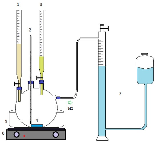
Figure 1.
Schematic representation of the experimental setup: (1) alkaline KBH4 solution feeding, (2) thermometer, (3) HCl solution feeding, (4) catalyst, (5) water bath, (6) hot plate, (7) gas burette system.
According to the experimental plan, the hydrolysis experiments were carried out from 293 K to 333 K. These experiments were repeated twice. The hydrogen generation rate (HGR) was calculated from the ratio of the slope of the graph of the volume of hydrogen produced against time at a linear regime rate to the amount of catalyst coated [20,38,39].
The DoE is a process-analysis methodology in which, after analysis of experimental results, some of the independent parameters that influence an experiment are selected and modified in a controlled manner to detect their effect on a targeted response [40]. Using this methodology, desired optimal conditions are achieved faster, more economically, and with more reliable results than with the traditional method [37]. RSM is a collection of mathematical and statistical techniques based on the properties of a polynomial math equation of experimental data. The aim is to optimize levels of independent variables to reach the best system performance at the same time [41]. In this study, an experimental plan was made using the central composite model from the RSM. The temperature, the amount of catalyst, and the volume of 0.5 M HCl were chosen as independent variables. The HGR values selected in response were calculated for each experimental condition. Then, the individual and two-way interaction contributions of each independent variable that affected the HGR value were examined simultaneously. Their effects on the response were evaluated using analysis of variance (ANOVA).
3. Results and Discussion
3.1. Characterization
Depending on the working conditions of the coating process, the material to be used as a target can be coated on any surface via the magnetron-sputtering process. Coatings made via the magnetron-sputtering technique are columnar and porous [34,42]. Section and surface images of the prepared thin-film catalysts under FE-SEM are shown in Figure 2. The coating thicknesses were seen to be 600 nm for NiCr and 500 nm for NiV. According to the SEM figures, the NiCr and NiV catalysts were thin-film, homogenous, and columnar. In addition, the porous structures can be seen clearly in the surface images. In solid solutions, chromium and vanadium atoms intrude between nickel atoms, reducing the column diameters of catalyst surfaces [43,44]. Thus, catalysts with porosity are obtained [45]. Moreover, no difference was observed in the FE-SEM images of the NiCr and NiV coatings except for in the film thickness.
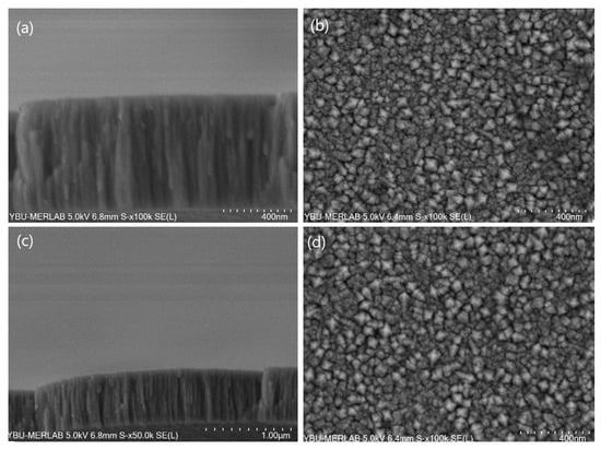
Figure 2.
The scanning electron microscopy images of the prepared thin-film catalysts. For the NiCr coating catalyst: (a) cross-section SEM images and (b) close-up planar SEM images. For the NiV coating catalyst: (c) cross-section SEM images and (d) close-up planar SEM images.
The characteristic peaks of the catalysts according to X-ray diffraction (XRD) measurement are shown in Figure 3. The XRD curves have been smoothed. It was seen that the metal alloys were coated in a nanocrystalline structure. The NiCr peaks were 44.3°, 51.96°, 76.1°, and 92.44°, and the NiV peaks were 44.1°, 48.26°, 51.94°, 76.4°, and 93°. The crystal sequences of these peaks were taken in the XRD library.
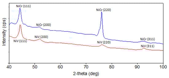
Figure 3.
XRD patterns of thin-film catalysts. The blue line is the XRD curve of the NiCr catalyst, and the red line is the XRD curve of the NiV catalyst.
When the SEM images and XRD measurements were evaluated together, porous and nanocrystalline catalysts were seen to be prepared. The Scherrer formula, which is widely used in the literature, gives crystal-size information from XRD data. This formula is given in Equation (2). In this equation, Dhkl is the crystallinity size, K is the particle-shape factor, λ is the X-ray wavelength, βhkl is half of the width of the peak reflection, and θ is the Bragg angle [46]. Using the Scherrer formula, the crystal dimensions of NiCr and NiV were found to be about 9 nm and 7 nm, respectively.
In addition, SEM/EDS analysis was carried out on the remaining solutions after the reaction. EDS data and SEM images are given in Figure 4. The oxygen percentage was found to be higher than calculated based on Equation (1). It was thought that the KBH4 given in Equation (3) reacted with hydrochloric acid, in a side reaction, to form boric acid [47].
KBH4 + 3H2O + HCl → 4H2 + H3BO3 + KCl
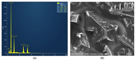
Figure 4.
SEM/EDS analysis of KBH4 hydrolysis products in an acidic medium: (a) EDS data and (b) SEM images of the remaining solutions after the reaction.
In addition, as shown in Figure 4, SEM/EDS analyses of the remaining solution detected no nickel, chromium, or vanadium. In this case, the prepared catalysts were understood to be stable under the reaction conditions and adhered well to the slide.
3.2. Experiment Design and HGR Value of Each Experiment
The experiment plan was designed according to the central composite design; the HGR value of each experiment is given in Table 1. Using the central composite experimental design model in optimization, the regression models for the response surface method within the determined operating conditions were obtained. Mathematical Equation (4) was given for the NiCr experimental system and Equation (5) was given for the NiV experimental system.
HGRNiCr = –329,502 + (2370 × Temperature) − (177,524 × Amt of cat) + (17,355 × Volume of HCI) − (4.19 × Temperature × Temperature) + (16,337 × Amt of cat × Amt of cat) + (54 × Volume of HCI × Volume of HCI) + (567 × Temperature × Amt of cat) − (18.5 × Temperature × Volume of HCI) − (6078 × Amt of cat × Volume of HCI)
HGRNiV = –547,478 − (4574 × Temperature) − (329,845 × Amt of cat) + (5774 × Volume of HCI) − (9.14 × Temperature × Temperature + (16,052 × Amt of cat × Amt of cat) + (170 × Volume of HCI × Volume of HCI) + (1092 × Temperature × Amt of cat) + (23.9 × Temperature × Volume of HCI) − (7363 × Amt of cat × Volume of HCI)

Table 1.
Experimental plan and HGR values.
3.3. Statistical Results and Optimum Conditions
A mathematical expression was derived using RSM to determine the HGR under optimum operating conditions. Minitab 21 statistical software was used to analyze the data. The correlation coefficient (R2) and adjusted correlation coefficient (Adj-R2) of the selected response were indicators of mathematical-model acceptance. While the R2 value of the experimental system that used the nickel–chromium catalyst was 99.09 and the respective Adj-R2 value was 98.08, the R2 value of the experimental system that used the nickel–vanadium catalyst was 99.34, and the respective Adj-R2 value was 98.59.
Analysis-of-variance tables for the NiCr and NiV experiment systems are given in Table 2 and Table 3, respectively. In this ANOVA, the F values of the regression model developed for the NiCr and NiV experimental systems were found to be 97.3 and 132.8, respectively. These results show that regression models are important for responses. For both catalyst systems, the independent variable that most affected the HGR value, according to the F value, was the volume of 0.5 M HCl. In addition, another indicator that showed the effectiveness of the independent parameters on the response was the P value, which showed that the effect of the parameters that were less than 0.05 on the response was significant; if it were higher than 0.05, the effect would not be much. When the p values in Table 2 and Table 3 are examined, it can be seen that the individual, square, and two-way interaction expressions of the independent parameters in the mathematical model are important. However, the two-way interactions of the temperature with the volume of 0.5 M HCl, the square of the temperature, and the square of the volume of 0.5 M HCl were less effective for the response of NiCr catalyst-system. The two-way interaction of temperature with the volume of 0.5 M HCl and the square of volume of 0.5 M HCl for the NiV catalyst system components were less effective in the mathematical model.
Table 2.
Analysis of variance for NiCr experiment system.
Table 3.
Analysis of variance for NiV experiment system.
The surface plot models given in Figure 5 show the changes of the selected variables with those of the HGR in three dimensions according to the experimental design prepared using RSM. Figure 6 shows contour plots of the HGR values of the NiCr system and the NiV system. When Figure 5 and Figure 6 are examined, it can be seen that the HGR value was positively affected by the volume of 0.5 M HCI, the temperature, and the amount of catalyst.
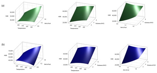
Figure 5.
Surface plots of HGR ((a) NiCr system, (b) NiV system; 1.225 g NiCr catalyst, 4 mL 0.5 M HCI at 313 K).
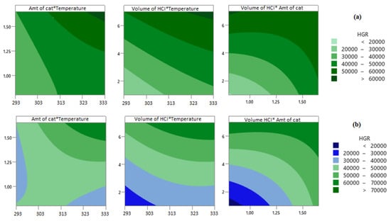
Figure 6.
Contour plots of HGR for (a) NiCr system and (b) NiV system.
When the amount of a catalyst is increased, the reaction time decreases. Therefore, the HGR value increases. During a reaction, the catalyst is coated with potassium metaborate, which is a by-product, on active sites. Moreover, this causes slow mass transfer of KBH4, which causes a decrease in catalytic activity. Hence, the amount of catalyst is important [19]. It is possible to obtain faster hydrogen production in a shorter time via increasing the temperature in hydrolysis reactions because temperature is directly related to reaction kinetics. Similar results have been seen in the literature [12,48]. Hydroxide-ion concentration greatly slows down the hydrolysis reaction of KBH4 because KBH4 is stable in alkaline media [48]. HCl reduces the pH of environments by reacting with NaOH. Therefore, it accelerates the hydrolysis reaction by reducing OH activity. It also cleans the catalyst surface [49]. The ambient pH value has been seen to be quite effective on the HGR. It is possible to realize faster hydrogen production in a shorter time by increasing the ambient temperature because the temperature is one of the parameters that directly affects reaction kinetics. Information on acceleration of the hydrogen production process via increasing the ambient temperature in the hydrolysis reaction of potassium borohydride is also included in the literature [19,20].
3.4. Optimization Process and Reusability of Catalysts
In order to verify the results obtained from the regression model obtained as a result of RSM, experiments were carried out under predicted conditions. In order to verify the optimized results, the case where the hydrogen production rate was maximum was chosen. The recommended optimum conditions were 1.65 g of catalyst, 6% KBH4, 3% NaOH, and 7 mL of 0.5 M HCl solution added at 333 K. The confidence interval of the regression model was chosen to be 95%. A comparison of the estimated and experimental HGR values is given in Table 4. When the experiments were carried out under optimum conditions, the HGR values for NiCr and NiV were calculated as 68.9 L·min−1·gcat−1 and 76.5 L·min−1·gcat−1, respectively. These results were found to be compatible with the relevant regression model and were within the confidence interval. Figure 7 shows the generated hydrogen volume versus the time of the validation experiment.
Table 4.
Comparison of estimated and experimental HGR values.
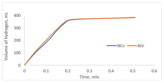
Figure 7.
Graph of generated hydrogen volume versus time (1.65 g of catalyst, 6% KBH4, 3% NaOH, and 7 mL of 0.5 M HCl at 333 K).
Some of the KBH4 hydrolysis conditions and their HGR values from the literature are displayed in Table 5. As can be seen in the table, the experimental conditions in the literature were different. Consequently, the HGR value for each system also changed. The HGR values in this study are quite notable. In this study, the preparation of nanoporous thin films of each catalyst and the addition of HCl solution to each reaction medium were seen to have a positive effect on the reaction rate. In addition, in the catalysts prepared in this study, only the effect of the coating was seen. HGR values were expected to increase if a material with a catalytic effect were used instead of a slide as a catalyst support material.
Table 5.
Some catalysts for KBH4 hydrolysis.
Although high HGR values were achieved in the hydrolysis experiments conducted under optimum conditions, the reusability tests of the catalysts used were not carried out under these conditions. The KBH4 hydrolysis reaction is an exothermic reaction [53]. In addition, an increase in temperature and low-pH environment would have negatively affected the thin-film catalysts. Therefore, in order to understand the reusability of catalysts in KBH4, hydrolysis experiments were carried out with 1.5 g of catalyst, 6% KBH4, 3% NaOH, and 3.1 mL of 0.5 M HCl at 323 K.
In the reusability tests of the catalyst experiments, after each hydrolysis experiment was completed, the catalyst was washed with deionized water, dried, and then used as a catalyst in the experiment again. In the first round of hydrolysis experiments carried out under these conditions, the HGR value for NiCr was calculated to be 52,347 mL·min−1·g−1, and the HGR value for NiV was calculated to be 55,630 mL·min−1·g−1. A graph of the reusability of the thin-film catalysts for KBH4 hydrolysis is given in Figure 8. As can be seen from the graph, the catalysts’ very stable and catalytic activities, especially in the first three cycles, make them suitable for reuse. Since the prepared catalysts had a heteroatomic structure, their stability and catalytic activities were good [54]. The catalytic performances of the NiCr and NiV catalysts in KBH4 hydrolysis were seen to be quite similar. The hydrolysis characteristic could be said to be generally nickel-based. However, NiCr produced hydrogen more slowly than NiV produced hydrogen. The reason for this is that vanadium exhibited a very good catalytic performance despite its small amount because it is a good reducing agent [55]. However, when these catalysts were examined in terms of reuse, NiCr was seen to be more durable.
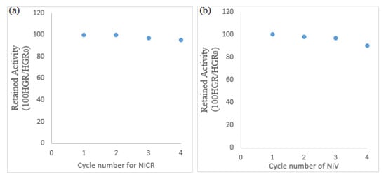
Figure 8.
The reusability of thin-film catalysts for KBH4 hydrolysis for four cycles: (a) NiCr catalyst reusability and (b) NiV catalyst reusability.
In addition, potassium metaborate, which is a KBH4 hydrolysis byproduct, first dispersed on the catalyst surface in a simple way, then agglomerated and formed a complex microstructure. Metaborate oligomers with weak intermolecular reactions, especially seen in hydrolysis of concentrations greater than 5% KBH4, are thought to directly affect the catalyst cycle [18].
3.5. The Proposed Mechanism of Catalyzed Potassium-Borohydride Hydrolysis
The added acid solution first undergoes a neutralization reaction with the base in the feed solution. As a result of the neutralization reaction, the reaction medium becomes acidic, basic, or neutral. The reaction mechanism of the catalyzed hydrolysis of potassium borohydride is suggested to occur in a neutral or basic medium similar to References [18,26,56,57], following these reaction mechanism steps: Firstly, BH4− ions and water molecule are chemisorbed on the catalyst. Afterward, H− is transferred from the BH4− to an unoccupied adjoining catalyst. Then, the hydrogen atom receives an electron from the catalyst and leaves the catalyst site in hydridic form (H−). The hydridic hydrogen reacts with a water molecule to produce H2 and OH−. Finally, this hydroxide anion reacts with boron in BH3 to generate BH3(OH)−. Consequently, the H− is transferred from each BH3(OH)− ion to the unoccupied adjoining catalyst. The cycle of hydrogen absorption on metal sites continues until BH3(OH)− forms B(OH)4− during each cycle. Since the reaction product in this last step is not supported by the catalyst, it reduces the rate of the hydrolysis reaction. The proposed KBH4 hydrolysis mechanisms are given in Figure 9. However, the surfaces of the catalysts used for the reaction mechanism recommended in this study were not analyzed. In KBH4 hydrolysis reaction in an acidic medium, unlike the reaction in the basic medium, the BH4− ion reacts with both water and HCI [53]. Since there is more H+ in the environment, H2 is thought to be produced more easily with the electrons from BH4− ions. This situation reflects the hydrogen production rate positively.
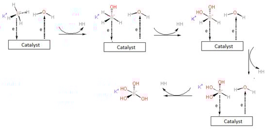
Figure 9.
The proposed KBH4 hydrolysis mechanisms.
4. Conclusions
Using response surface methodology, the experimental system could be easily modeled in a short time with a small number of experiments, and the individual and bidirectional interactions of the variables that affected the response of the system could be examined simultaneously. In this study, thin-film NiCr and NiV catalysts prepared with the magnetron sputtering method were used for hydrolysis of KBH4. Experimental studies were planned using the central composite design, and the efficiency of the parameters was determined with analysis of variance. The optimum parameters for the maximum hydrogen production rate in hydrolysis of KBH4 were 1.65 g of catalyst, 6% KBH4, 3% NaOH, and 7 mL of 0.5 M HCl at 333 K. The maximum HGR values for NiCr and NiV were calculated to be 68.9 L·min−1·gcat−1 and 76.5 L·min−1·gcat−1, respectively. This study shows that NiCr- and NiV-catalyzed KBH4 hydrolysis reaction systems for hydrogen generation can be alternating hydrogen production processes.
Funding
This research was funded by Ankara Yıldırım Beyazıt University Scientific Research Unit grant number 2148.
Conflicts of Interest
The authors declare no conflict of interest.
References
- Kong, X.; Yang, L.; Cheng, Z.; Zhang, S. Bi-modified SrTiO3-based ceramics for high-temperature energy storage applications. J. Am. Ceram. Soc. 2020, 103, 1722–1731. [Google Scholar] [CrossRef]
- Tripathi, L.; Mishra, A.; Dubey, A.K.; Tripathi, C.; Baredar, P. Renewable energy: An overview on its contribution in current energy scenario of India. Renew. Sustain. Energy Rev. 2016, 60, 226–233. [Google Scholar] [CrossRef]
- Shafiee, S.; Topal, E. When will fossil fuel reserves be diminished? Energy Policy 2009, 37, 181–189. [Google Scholar] [CrossRef]
- Olabi, A.; Abdelghafar, A.A.; Baroutaji, A.; Sayed, E.T.; Alami, A.H.; Rezk, H.; Abdelkareem, M.A. Large-vscale hydrogen production and storage technologies: Current status and future directions. Int. J. Hydrogen Energy 2021, 46, 23498–23528. [Google Scholar] [CrossRef]
- Sdanghi, G.; Maranzana, G.; Celzard, A.; Fierro, V. Review of the current technologies and performances of hydrogen compression for stationary and automotive applications. Renew. Sustain. Energy Rev. 2019, 102, 150–170. [Google Scholar] [CrossRef]
- Acar, C.; Dincer, I. Review and evaluation of hydrogen production options for better environment. J. Clean. Prod. 2019, 218, 835–849. [Google Scholar] [CrossRef]
- Nikolaidis, P.; Poullikkas, A. A comparative overview of hydrogen production processes. Renew. Sustain. Energy Rev. 2017, 67, 597–611. [Google Scholar] [CrossRef]
- Principi, G.; Agresti, F.; Maddalena, A.; Russo, S.L. The problem of solid state hydrogen storage. Energy 2009, 34, 2087–2091. [Google Scholar] [CrossRef]
- Zlotea, C.; Latroche, M. Role of nanoconfinement on hydrogen sorption properties of metal nanoparticles hybrids. Physicochem. Eng. Asp. 2013, 439, 117–130. [Google Scholar] [CrossRef]
- Salih Keskin, M.; Şahin, Ö.; Horoz, S. Efficiency of TiO2-supported Ni-Mo-Ru–B catalyst for hydrogen production from potassium borohydride hydrolysis. J. Aust. Ceram. Soc. 2022, 58, 973–979. [Google Scholar] [CrossRef]
- Özgür, D.Ö.; Şimşek, T.; Özkan, G.; Akkuş, M.S.; Özkan, G. The Hydroloysis of ammonia borane by using Amberlyst-15 supported catalysts for hydrogen generation. Int. J. Hydrogen Energy 2018, 43, 10765–10772. [Google Scholar] [CrossRef]
- Akkuş, M.S.; Murathan, H.B.; Özgür, D.Ö.; Özkan, G.; Özkan, G. New insights on the mechanism of vapour phase hydrolysis of sodium borohydride in a fed-batch reactor. Int. J. Hydrogen Energy 2018, 43, 10734–10740. [Google Scholar] [CrossRef]
- Li, Z.; Gao, M.; Wang, S.; Zhang, X.; Gao, P.; Yang, Y.; Sun, W.; Liu, Y.; Pan, H. In-situ introduction of highly active TiO for enhancing hydrogen storage performance of LiBH4. Chem. Eng. J. 2022, 433, 134485. [Google Scholar] [CrossRef]
- Moussa, G.; Moury, R.; Demirci, U.B.; Şener, T.; Miele, P. Boron-based hydrides for chemical hydrogen storage. Int. J. Energy Res. 2013, 37, 825–842. [Google Scholar] [CrossRef]
- Wang, L.; Huang, L.; Jiao, C.; Huang, Z.; Liang, F.; Liu, S.; Wang, Y.; Zhang, H. Preparation of Rh/Ni bimetallic nanoparticles and their catalytic activities for hydrogen generation from hydrolysis of KBH4. Catalysts 2017, 7, 125. [Google Scholar] [CrossRef]
- Liu, J.; Ma, Y.; Yang, J.; Sun, L.; Guo, D.; Xiao, P. Recent advance of metal borohydrides for hydrogen storage. Front. Chem. 2022, 10, 945208. [Google Scholar] [CrossRef]
- Comanescu, C. Complex Metal Borohydrides: From Laboratory Oddities to Prime Candidates in Energy Storage Applications. Materials 2022, 15, 2286. [Google Scholar] [CrossRef]
- Pope, F.; Watson, N.I.; Deblais, A.; Rothenberg, G. Understanding the Behaviour of Real Metaborates in Solution. ChemPhysChem 2022, 23, e202200428. [Google Scholar] [CrossRef]
- Kilinc, D.; Sahin, O. High volume hydrogen evolution from KBH4 hydrolysis with palladium complex catalyst. Renew. Energy 2020, 161, 257–264. [Google Scholar] [CrossRef]
- Kılınç, D.; Şahin, Ö. Metal-Schiff Base complex catalyst in KBH4 hydrolysis reaction for hydrogen production. Int. J. Hydrogen Energy 2019, 44, 18848–18857. [Google Scholar] [CrossRef]
- Yeh, J.-W. Overview of High-Entropy Alloys. In High-Entropy Alloys; Gao, M.C., Yeh, J.-W., Liaw, P.K., Zhang, Y., Eds.; Springer: Berlin/Heidelberg, Germany, 2016; pp. 1–19. [Google Scholar]
- Yao, C.; Zhuang, L.; Cao, Y.; Ai, X.; Yang, H. Hydrogen release from hydrolysis of borazane on Pt-and Ni-based alloy catalysts. Int. J. Hydrogen Energy 2008, 33, 2462–2467. [Google Scholar] [CrossRef]
- Hou, K.; Hou, X.; Ye, X.; Li, D.; Suo, G.; Xie, L.; Shu, Q.; Cao, Q.; Bai, J. Carbon nanotubes and (Mg10Ni) 85Ce15 synergistically activate Mg-Al alloy waste for efficiently hydrolysis hydrogen generation. Fuel 2022, 324, 124829. [Google Scholar] [CrossRef]
- Guo, J.; Li, X.; Duan, H.; Zhang, H.; Jia, Q.; Zhang, S. Graphene supported Pt–Ni bimetallic nanoparticles for efficient hydrogen generation from KBH4/NH3BH3 hydrolysis. Int. J. Hydrogen Energy 2022, 47, 11601–11610. [Google Scholar] [CrossRef]
- Eom, K.; Cho, E.; Kwon, H. Feasibility of on-board hydrogen production from hydrolysis of Al–Fe alloy for PEMFCs. Int. J. Hydrogen Energy 2011, 36, 12338–12342. [Google Scholar] [CrossRef]
- Patel, N.; Fernandes, R.; Miotello, A. Promoting effect of transition metal-doped Co–B alloy catalysts for hydrogen production by hydrolysis of alkaline NaBH4 solution. J. Catal. 2010, 271, 315–324. [Google Scholar] [CrossRef]
- Xu, D.; Wang, H.; Guo, Q.; Ji, S. Catalytic behavior of carbon supported Ni–B, Co–B and Co–Ni–B in hydrogen generation by hydrolysis of KBH4. Fuel Process. Technol. 2011, 92, 1606–1610. [Google Scholar] [CrossRef]
- Shahidi, S.; Moazzenchi, B.; Ghoranneviss, M. A review-application of physical vapor deposition (PVD) and related methods in the textile industry. Eur. Phys. J. Appl. Phys. 2015, 71, 31302. [Google Scholar] [CrossRef]
- Yun, S.; Oyama, S.T. Correlations in palladium membranes for hydrogen separation: A review. J. Membr. Sci. 2011, 375, 28–45. [Google Scholar] [CrossRef]
- Arzac, G.; Fernández, A. Advances in the implementation of PVD-based techniques for the preparation of metal catalysts for the hydrolysis of sodium borohydride. Int. J. Hydrogen Energy 2020, 45, 33288–33309. [Google Scholar] [CrossRef]
- Qing, W.; Liu, F.; Yao, H.; Sun, S.; Chen, C.; Zhang, W. Functional catalytic membrane development: A review of catalyst coating techniques. Adv. Colloid Interface Sci. 2020, 282, 102207. [Google Scholar] [CrossRef]
- Veith, G.M.; Lupini, A.R.; Pennycook, S.J.; Dudney, N.J. The Use of Magnetron Sputtering for the Production of Heterogeneous Catalysts; Oak Ridge National Lab. (ORNL): Oak Ridge, TN, USA, 2006. [Google Scholar]
- Shaginyan, L.; Mišina, M.; Kadlec, S.; Jastrabık, L.; Mackova, A.; Peřina, V. Mechanism of the film composition formation during magnetron sputtering of WTi. J. Vac. Sci. Technol. A Vac. Surf. Film. 2001, 19, 2554–2566. [Google Scholar] [CrossRef]
- Kelly, P.J.; Arnell, R.D. Magnetron sputtering: A review of recent developments and applications. Vacuum 2000, 56, 159–172. [Google Scholar] [CrossRef]
- Sağır, K.; Elçiçek, H.; Özdemir, O.K. Optimization of catalyst preparation conditions for hydrogen generation in the presence of Co–B using Taguchi method. Int. J. Hydrogen Energy 2021, 46, 5689–5698. [Google Scholar] [CrossRef]
- Wahdame, B.; Candusso, D.; François, X.; Harel, F.; Pera, M.-C.; Hissel, D.; Kauffmann, J.M. Analysis of a fuel cell durability test based on design of experiment approach. IEEE Trans. Energy Convers. 2008, 23, 1093–1104. [Google Scholar] [CrossRef]
- Özkan, G.; Akkuş, M.S.; Özkan, G. The effects of operating conditions on hydrogen production from sodium borohydride using Box-Wilson optimization technique. Int. J. Hydrogen Energy 2019, 44, 9811–9816. [Google Scholar] [CrossRef]
- Karakaş, D.E. A novel cost-effective catalyst from orange peel waste protonated with phosphoric acid for hydrogen generation from methanolysis of NaBH4. Int. J. Hydrogen Energy 2022, 47, 12231–12239. [Google Scholar] [CrossRef]
- Kilinc, D.; Sahin, O. Ruthenium-Imine catalyzed KBH4 hydrolysis as an efficient hydrogen production system. Int. J. Hydrogen Energy 2021, 46, 20984–20994. [Google Scholar] [CrossRef]
- Akkuş, M.S.; Karabudak, S. Biyoproses Çalışmalarında Deneysel Tasarım Yönteminin Uygulanması. İleri Müh. Çalış. Tek. Der. 2020, 1, 188–197. [Google Scholar]
- Khuri, A.I.; Mukhopadhyay, S. Response surface methodology. Wiley Interdiscip. Rev. Comput. Stat. 2010, 2, 128–149. [Google Scholar] [CrossRef]
- Tian, C.; Cai, H.; Xue, Y. Effect of Working Pressure on Tribological Properties of Ce-Ti/MoS2 Coatings Using Magnetron Sputter. Coatings 2022, 12, 1576. [Google Scholar] [CrossRef]
- Chiu, Y.-J.; Shen, C.-Y.; Chang, H.-W.; Jian, S.-R. Characteristics of Iron-Palladium alloy thin films deposited by magnetron sputtering. Results Phys. 2018, 9, 17–22. [Google Scholar] [CrossRef]
- Sheftel, E.; Tedzhetov, V.; Kiryukhantsev-Korneev, P.V.; Harin, E.; Usmanova, G.S.; Zhigalina, O. Investigation of the Processes of the Formation of a Nonequilibrium Phase-Structural State in FeTiB Films Obtained by Magnetron Sputtering. Russ. J. Non-Ferr. Met. 2020, 61, 753–761. [Google Scholar] [CrossRef]
- Ahmadipour, M.; Ayub, S.N.; Ain, M.F.; Ahmad, Z.A. Structural, surface morphology and optical properties of sputter-coated CaCu3Ti4O12 thin film: Influence of RF magnetron sputtering power. Mater. Sci. Semicond. Process. 2017, 66, 157–161. [Google Scholar] [CrossRef]
- Bokuniaeva, A.; Vorokh, A. Estimation of particle size using the Debye equation and the Scherrer formula for polyphasic TiO2 powder. J. Phys. Conf. Series. 2019, 1410, 012057. [Google Scholar] [CrossRef]
- Kilday, M.V.; Johnson, W.H.; Prosen, E.J. Heats of Hydrolysis and Formation of Dimethoxychloroborane. J. Res. Natl. Bur. Standards. Sect. A Phys. Chem. 1961, 65, 435. [Google Scholar] [CrossRef]
- Onat, E.; Şahin, Ö.; Izgi, M.S.; Horoz, S. An efficient synergistic Co@ CQDs catalyst for hydrogen production from the hydrolysis of NH3BH3. J. Mater. Sci. Mater. Electron. 2021, 32, 27251–27259. [Google Scholar] [CrossRef]
- Paladini, M.; Arzac, G.; Godinho, V.; Hufschmidt, D.; de Haro, M.J.; Beltrán, A.M.; Fernández, A. The role of cobalt hydroxide in deactivation of thin film Co-based catalysts for sodium borohydride hydrolysis. Appl. Catal. B Environ. 2017, 210, 342–351. [Google Scholar] [CrossRef]
- Saka, C.; Balbay, A. Fast and effective hydrogen production from ethanolysis and hydrolysis reactions of potassium borohydride using phosphoric acid. Int. J. Hydrogen Energy 2018, 43, 19976–19983. [Google Scholar] [CrossRef]
- Erhan, O.; Aslan, M.; Izgi, M.S. Kobalt bazli bimetalik nanokatalizörün potasyum borhidrür hidroliz tepkimesi üzerindeki katalitik etkisinin incelenmesi. KONJES 2021, 9, 200–212. [Google Scholar]
- Keskin, M.; AĞIRTAŞ, M.; Şahin, Ö.; Horoz, S. An efficient TiO2-supported ruthenium (Ru/TiO2) catalyst for electrochemical hydrogen generation from aqueous potassium borohydride. Dig. J. Nanomater. 2020, 15, 281–287. [Google Scholar]
- Balbay, A.; Şahin, Ö.; Saka, C. Effect of acid addition on hydrogen production from potassium borohydride hydrolysis. Energy Sources Part A: Recovery Util. Environ. Eff. 2017, 39, 1383–1389. [Google Scholar] [CrossRef]
- Liu, W.; Stoddart, J.F. Emergent behavior in nanoconfined molecular containers. Chem 2021, 7, 919–947. [Google Scholar] [CrossRef]
- Kauppila, J.; Lund, L.; Laiho, T.; Salomäki, M.; Kankare, J.; Lukkari, J. Effective low temperature reduction of graphene oxide with vanadium (III). J. Mater. Chem. C 2014, 2, 3602–3609. [Google Scholar] [CrossRef]
- Fernandes, R.; Patel, N.; Miotello, A. Hydrogen generation by hydrolysis of alkaline NaBH4 solution with Cr-promoted Co–B amorphous catalyst. Appl. Catal. B Environ. 2009, 92, 68–74. [Google Scholar] [CrossRef]
- Demirci, U.B.; Miele, P. Reaction mechanisms of the hydrolysis of sodium borohydride: A discussion focusing on cobalt-based catalysts. Comptes Rendus Chim. 2014, 17, 707–716. [Google Scholar] [CrossRef]
Publisher’s Note: MDPI stays neutral with regard to jurisdictional claims in published maps and institutional affiliations. |
© 2022 by the author. Licensee MDPI, Basel, Switzerland. This article is an open access article distributed under the terms and conditions of the Creative Commons Attribution (CC BY) license (https://creativecommons.org/licenses/by/4.0/).