Abstract
Stand-alone DC microgrids have multiple distributed generation (DG) sources that meet the required demand (load) by using droop control to achieve load (current) sharing between the DGs. The use of droop control leads to a voltage drop at the DC bus. This paper presents a distributed secondary control scheme to simultaneously ensure current sharing between the DGs and regulate the DC bus voltage. The proposed control scheme eliminates the voltage deviation and ensures balanced current sharing by combining the voltage and current errors in the designed secondary control loop. A new flight-based artificial bee colony optimization algorithm is proposed. This selects the parameters of the distributed secondary control scheme to achieve the objectives of the proposed controller. A state–space model of the DC microgrid is developed by using eigenvalue observation to test the impacts of the proposed optimized distributed secondary controller on the stability of the DC microgrid system. A real-time test system is developed in MATLAB/Simulink and used in a Speedgoat real-time simulator to verify the performance of the proposed control scheme for real-world applications. The results show the robustness of the proposed distributed secondary control scheme in achieving balance current sharing and voltage regulation in the DC microgrid with minimal oscillations and fast response time.
1. Introduction
To address issues such as a lack of electricity, the limited availability of electricity, environmental concerns due to the use of fossil fuels, cost-effective generation, and advancements in renewable energy source (RES)-based power generation, researchers around the world have devised a combined framework of power generation by using traditional and non-conventional sources [1,2]. However, due to losses in undesirable power conversion processes, integrating RESs into the existing power grid could be complicated. As a result, the development of smaller grids, or microgrids, with their own generation sources, energy storage systems, loads, and control structures for remote regions is critical. Microgrids economically harness locally accessible RESs and distribute them to local loads for energy independence. Depending on the coupling bus, microgrids can be classified into AC, DC, and hybrid AC/DC [3]. They can be operated as stand-alone or grid-connected. Over the years, great strides have been achieved to improve the operation of AC microgrids [4]. However, DC microgrids are receiving appreciable attention in recent times because of their similar interface (DC) to most RESs and distributed generators (DGs), reduced control complexity (no frequency and reactive power controls), and better power quality, improved efficiency and stability [5]. Studies conducted in [6] showed that DC systems have a 15% improvement in voltage stability when compared with AC systems.
In a DC microgrid setup, the DGs are connected in parallel to a common DC bus. Thus, the control of the interfacing power electronics converter in each DG is a critical aspect of the stable operation of the microgrid. The control operations of a DC microgrid include load sharing, voltage regulation, power balancing, energy-storage management, and minimization of cost operation [7]. The hierarchical control framework can be categorized into primary, secondary, and tertiary controls. The primary control consists of the traditional inner proportional–integral (PI)-based current and voltage controllers in the power electronics converters of the DGs. When multiple DGs are connected in parallel, the droop control is added to the primary control loop to provide current/load sharing among the DGs. In [8], the conventional integral-type control is proposed to develop a droop controller to improve the transient performance of the converter and DC microgrid. In [9], the non-linear droop control is proposed to improve the performance of the conventional droop control which is usually deteriorated by the line impedance of the microgrid. A modified droop control scheme is proposed in [10] to mitigate the effects of the circulating current caused by voltage deviation in the DC microgrid.
In addition to the issue of current sharing among DGs in the DC microgrid, the problem of voltage regulation at the DC bus is imminent as a result of the voltage drop caused by the droop resistance used to implement the droop control. Therefore, current sharing and voltage regulation are the two main objectives of the control structure in the DC microgrid [11]. To achieve these objectives, an additional control layer (secondary control) is added to the control loop. The secondary control may be centralized, decentralized, or distributed [12]. In the centralized secondary control, the error signal is the input to a single controller, usually a PI control, and the output of the controller is sent to the primary control in all the DGs to eliminate the deviations caused by the droop control. The limitation of the centralized secondary is its vulnerability to single-point failure which could be catastrophic for the microgrid system [13]. The large communication bandwidth required in the centralized secondary control is another limitation. The decentralized secondary control solves these limitations because it requires little to no communication bandwidth. The control is achieved by setting the voltage and current references to be followed by each DG in the microgrid. Communication may be achieved by using the power cables or a low-bandwidth communication channel [14]. Although the decentralized secondary control is easy to implement, it has the limitation of deteriorating the overall performance of the DC microgrid. This is because of the absence of global communication; the output of the controller may be sufficient to compensate for the required deviation caused by the droop control [15].
In recent years, the distributed secondary control has been used to achieve the objectives of proportional current sharing and voltage regulation in DC microgrids because of its high reliability and stability [16]. In the distributed secondary control, each DG in the microgrid has its secondary controller that interacts with neighboring DGs via a communication topology to share information and achieve a consensus operation, forming a multiagent system. In [17], a distributed secondary control scheme is proposed for power allocation and voltage restoration in a DC microgrid. The proposed secondary control scheme employs the concept of pinning gain in the secondary voltage controller. The event-triggered communication topology is used in [18] to design a distributed voltage control scheme for an islanded DC microgrid. In [19], a leader–follower approach is adopted for a distributed finite-time secondary control scheme of a multiagent DC microgrid. In [20], a hybrid control method—continuous and discrete—is proposed to the problem of current sharing and eliminate voltage deviation at the DC bus of a microgrid. In [21], the game theory framework is used to design a distributed iterative algorithm for voltage regulation and proportional current sharing in a DC microgrid. The limitation of this approach is the high computational cost; it requires a huge amount of data to learn the operation of the DC microgrid for efficient performance.
From the literature survey, it is noted that the two control loops for current sharing and voltage regulation are required to design the secondary control loop. The addition of the secondary control output signal to the primary control loop usually causes a trade-off between current sharing and voltage regulation. Thus, the objective of this paper is to achieve a control that simultaneously ensures current sharing and voltage regulation with a trade-off. This paper proposes a distributed control scheme that is based on the linear combination of current sharing and voltage control loops in a secondary control layer of a stand-alone DC microgrid. Distributivity ensures resilience in the microgrid’s operation. To ensure distributivity, each DG in the microgrid has an individual secondary control; however, there is an exchange of information between the DGs to guarantee consensus operation. The control trade-off is eliminated by proposing a weighting parameter to balance the current sharing and voltage regulation objectives. The weighting parameter is selected by using a heuristic approach; a new flight-based artificial bee colony optimization algorithm is proposed. The proposed algorithm has the advantages of simple implementation, the ability to jump out of the local minimum and find the global optimum solution. The stability analysis of the proposed method is investigated by using the eigenvalue analysis method. Real-time simulation experiments are conducted for various operating conditions to test the robustness of the proposed distributed secondary control scheme to ensure current sharing and voltage regulation in the DC microgrid. The proposed method uses less bandwidth which reduces communication costs. Furthermore, the vulnerability of centralized secondary to single-point failure increases the operation cost of the microgrid.
The remainder of this paper is organized as follows. Section 2 presents the mathematical modeling of a DC microgrid and provides the state–space model of a typical DC microgrid system. Section 3 presents the proposed distributed secondary control scheme for the DC microgrid. Section 4 presents the proposed flight-based ABC optimization algorithm for the proposed controller. Section 5 presents the discussion of the results of the application of the proposed optimized distributed secondary control scheme in a DC microgrid by using different simulation scenarios. Section 6 presents the conclusion of the paper.
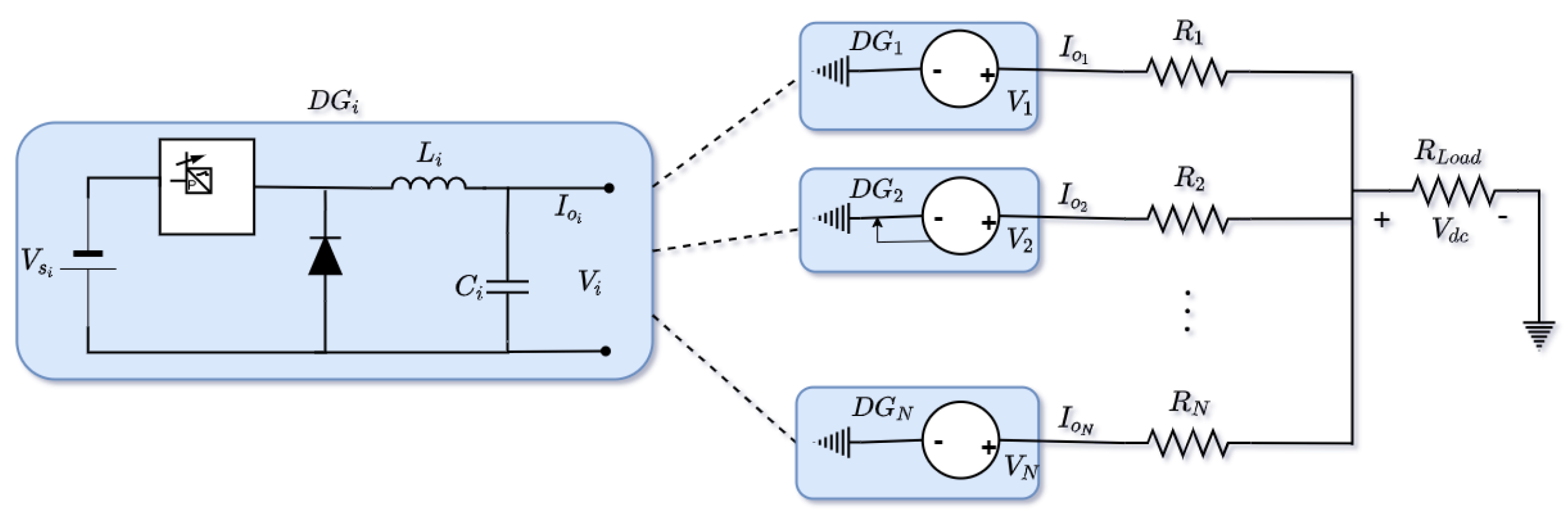
2. Mathematical Modeling of DC Microgrid
In this section, the mathematical model of the DC microgrid elements for small-signal analysis is derived. The configuration of the microgrid is such that all the microsources are connected in parallel to a common DC bus. Similarly, all loads within the microgrid are connected to the DC bus. The coordination and management of the microgrid are achieved by the hierarchical control scheme—primary, secondary, and tertiary controls [22]. However, the scope of this work is limited to the primary and secondary levels of control. The state-space model of the converter in a single DG and its controls is derived, and it can be extrapolated for multiple DGs within the DC microgrid setup.
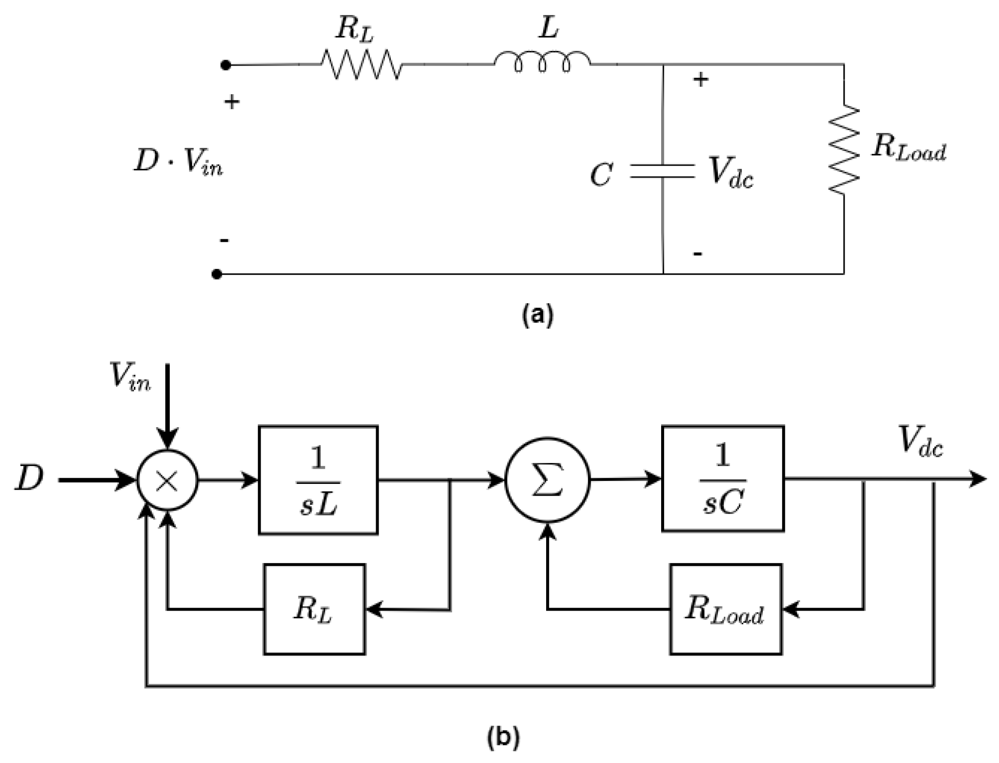
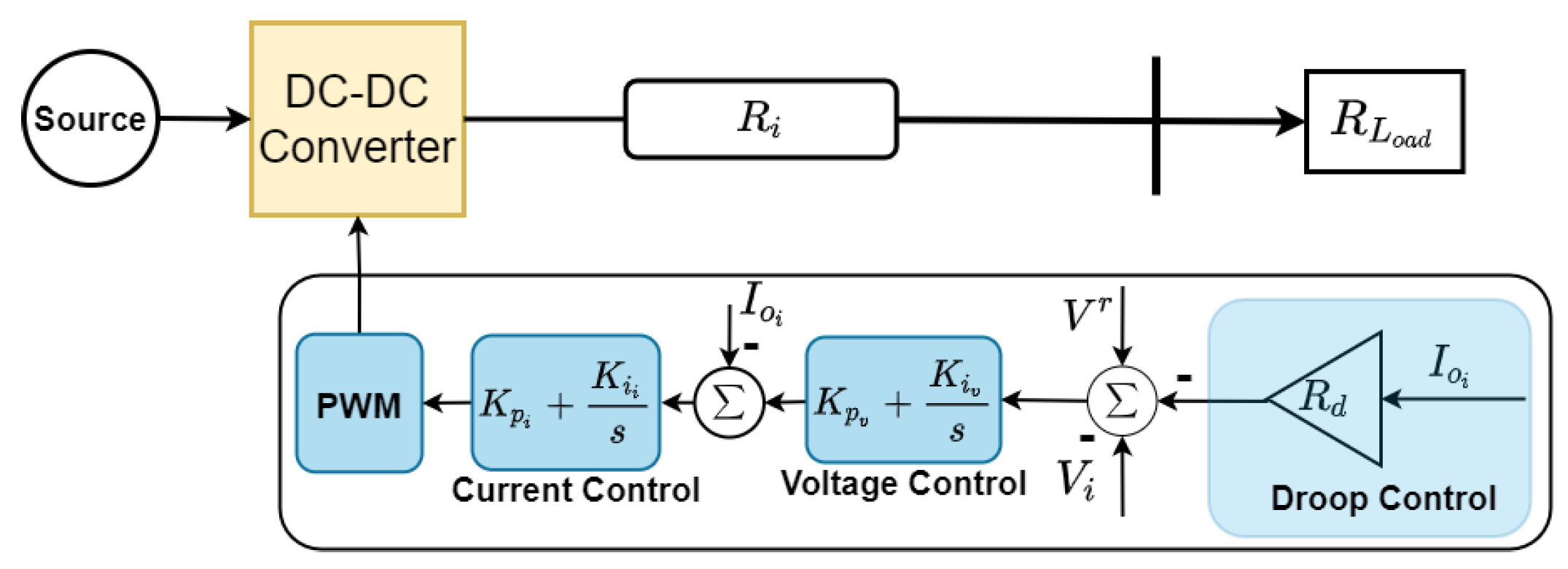
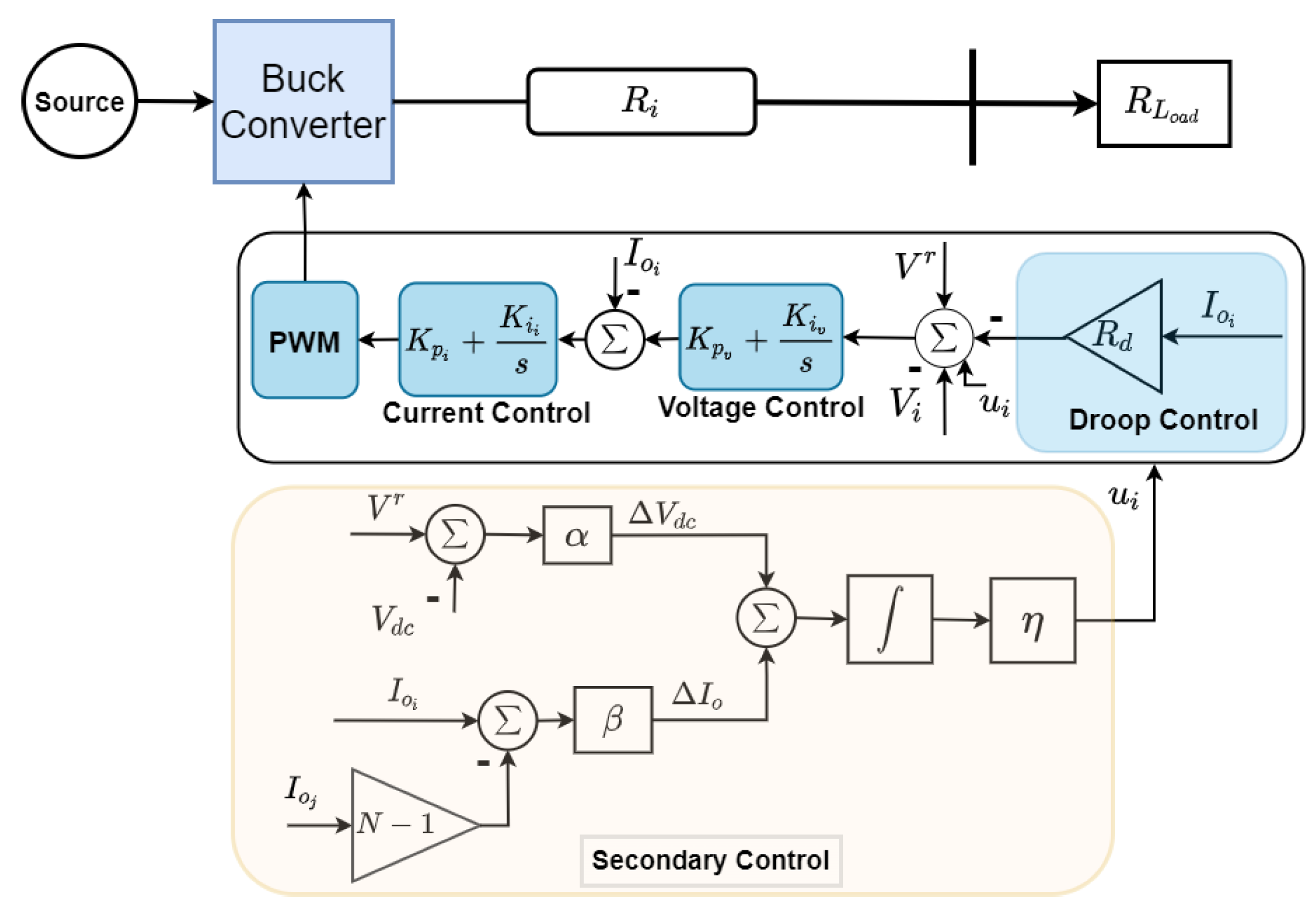
2.1. Buck Converter Modeling
To derive the state–space model of the dc/dc buck converter, the equivalent circuit shown in Figure 1a is sufficient to represent the average model of the converter by neglecting high-frequency dynamics of the converter. The buck converter steps down the input dc voltage () to a lower output dc voltage (). The dynamics of the converter can be mathematically modeled as
where are the converter’s capacitance, inductance, and resistance respectively, is the output current, D is the duty cycle of the converter, and is the total resistive load seen by the converter. To analyse the stability of the converter, (1) and (2) are transformed to the Laplace domain and rearranged into the transfer function as given in (3). The roots of the characteristic equation of (3) are
Figure 1.
(a) Equivalent circuit (b) block diagram of a buck converter.
The values of L and C can be calculated from
where is the peak ripple of the inductor’s current, is peak ripple of , and is the converter’s switching frequency. The block diagram of the buck converter is shown in Figure 1b.
2.2. Primary Control of a Buck Converter
The objective of the primary control loop is to ensure stability in the buck converter circuit during transients. The primary control basically consists of a current controller (PI type), a voltage controller (PI type), and a droop controller (P-type) as shown in Figure 2. The current controller generates the reference duty cycle for the pulse width modulation (PWM) of the converter to regulate its output current and the voltage controller produces the current reference for the current controller to regulate the output DC voltage. To avoid instability, the response of the current controller is designed to be faster than the response of the voltage controller.
Figure 2.
Primary control of buck converter of DC microgrid.
When more than one DC converter is connected in parallel to a common DC bus, the first level of control to achieve coordination among the converters is the droop control. The aim of the droop control is to ensure a specified current or load sharing ratio among the converters. Considering the DC microgrid setup in Figure 3, the DC bus voltage can be expressed as
where , , and are the reference voltage, line resistance and output current for the converter in the ith DG respectively. The reference voltage generated based on the droop control for current sharing is given as
where is the rated DC voltage and is the droop resistance of the ith converter. By inspecting (5) and (6) for converters in DG and DG that are connected to a common bus, the droop relationship can be deduced as
and
provided that the droop resistance is chosen to be larger than the line resistance.
Figure 3.
Electrical schematic of a stand-alone DC microgrid.
The stability of the primary control for the buck converter can be studied by developing the dynamic equations from the block diagram shown in Figure 2. The dynamic equation of the DC voltage reference error input to the voltage controller based on the action of the droop control for the converter in the ith DG is expressed as
The dynamic equation of the current reference error input from the PI voltage controller is
where and are the proportional and integral gains of the voltage controller. The output current and DC voltage equations to complete the state–space modelling of the buck converter for the DC microgrid can be expressed from (1) and (2) as
where and are the proportional and integral gains of the current controller. Using (9)–(12), the state-space model of the ith DG with primary control for DC microgrid application can be expressed in the general state-space format as
where is the state vector, is the state matrix given in (15), and are the input and output matrices given in (16), is the input vector and is the output vector
By inspecting (5), it can be deduced that if the current is greater than zero, the DC bus voltage will always deviate from the nominal value. From (6), it can also be inferred that when the droop resistance is large to achieve a more accurate current sharing, it leads to a deviation in the DC voltage. Thus, the primary control is unable to achieve balanced current sharing between multiple DGs without significant deviation in the DC bus voltage. To simultaneously achieve balanced current sharing and voltage regulation, secondary control is utilized.
3. Proposed Distributed Secondary Control Scheme
Based on the aforementioned drawback of the primary control, a new distributed secondary control scheme is developed for the simultaneous current sharing and voltage regulation of a stand-alone DC microgrid where multiple DGs are connected in parallel to a common DC bus. Each converter of the DG has its local (primary) controller that does not communicate with other local controllers in their respective DGs. The secondary control generates a new reference signal to offset the deviation caused by the droop control as shown in Figure 4. To overcome the limitation of single-point failure that is inherent with the traditional secondary control, the distributed secondary control scheme is implemented. In this scheme, each DG has its secondary control loop and can exchange information with other secondary controllers via a communication network. In this work, the objective of the proposed distributed secondary control scheme is to restore the DC bus voltage while ensuring balanced current sharing by the droop control. To begin the design of the distributed secondary scheme, we define the control objectives.
3.1. Control Objectives
The first control objective of the proposed distributed secondary controller is to regulate the DC bus voltage at its nominal value. The voltage deviation caused by the droop control can be deduced from (5) and (6) as
Figure 4.
Proposed secondary control for DC microgrid.
Hence, the voltage control objective can be defined as
The second control objective of the proposed distributed secondary controller is to ensure balanced current sharing, which leads to balanced power sharing among the parallel DGs. As mentioned earlier, the current sharing expression in (8) leads to voltage deviation. Therefore, the current sharing control objective for the ith DG can be defined as
where
where is the current sharing ratio of the ith DG and N is the number of DGs in the stand-alone DC microgrid.
3.2. Proposed Controller Design
To achieve the defined objective, we design the distributed secondary controller to offset the deviation caused by the droop control. The DC bus voltage as a result of the secondary control input can be expressed from (5) as
where is the input from the proposed secondary controller of the ith DG that is designed by using the simple feedback control law that is defined as
where is the total error or deviation that is expressed as
where , , and are the parameters of the proposed secondary control scheme. To investigate the impact of the proposed secondary controller on the stability of the DC microgrid, the dynamic equations for the controller are formulated. The voltage reference error input in (9), due to the presence of the secondary control, is modified as
The dynamic equation of the proposed distributed secondary controller can be expressed as
By using (10)–(12), (24), and (25), the state–space model of the secondary control-enabled ith DG can be expressed by using
where is the state vector, is the state matrix given in (28), and are the input and output matrices given in (29), is the input vector and is the output vector
The design of the parameters of the proposed distributed secondary control to achieve the current sharing and voltage regulation objectives is complex and time-consuming because they affect the response of the DG and impact the stability of the DC microgrid. From elementary investigation, setting a large value of results in faster convergence of the DC bus voltage objective whereas a large value of results in faster convergence of the current sharing objective. By convention, is chosen to be greater than because the current sharing objective is a consensus-based objective among all DGs whereas the voltage regulation objective is a global objective from the DC bus. To circumvent the tuning complexity, and increase the adaptability and flexibility of the distributed secondary controller, a new and improved tuning method is proposed to select appropriate because it is the weighting parameter between the current sharing and voltage regulation objectives.
4. Proposed Tuning Method for Distributed Secondary Control
In this section, a new tuning method for the parameters of the proposed distributed secondary control scheme is presented. The tuning method is the flight-based ABC optimization algorithm which uses the Levy flight algorithm to improve the performance of the traditional ABC optimization method.
4.1. Traditional ABC Algorithm
The ABC optimization algorithm is a heuristic computational method that imitates the pattern of a colony of bees in search of nectar locations (NLs). The bee colony is divided into three sets of bees [23]:
- (1)
- Collector bees—they explore for possible NLs and share these locations by dancing with other bees in the colony. The length of the dance indicates the quality of nectar in the location. The collector bee with a high-quality nectar location will dance longer than one with a low-quality nectar location.
- (2)
- Observer bees—they wait in the hive to receive NLs from the collector bees and search for these NLs by using the greedy selection process. The NLs with high quality are likely to attract more observer bees than NLs with low quality.
- (3)
- Scout bees—they are formerly collector bees whose NLs were abandoned as a result of low quality.
In the search process for NLs (possible solutions), the tasks of exploration and exploitation are simultaneous processes. The collector and observer bees perform the exploration task and the scout bees perform the exploitation process. For every NL, a collector bee is assigned. That is, the number of NLs in the search space corresponds to the number of collector bees. Moreover, the number of collector bees is equal to the number of observer bees. The scout bees start their exploitation when the collector bees have abandoned the NLs. The parameter that controls the abandonment of a particular NL is known as the “limit cycle.” The ABC algorithm initializes a random number of possible solutions for the the collector bees where is the number of collector bees. Each possible solution (NL) is a -dimensional vector where is the number of design variables to be optimized or tuned. The NLs indicate possible solutions whereas the quality of the NL represents the fitness value of the solution. After the initialization phase, the potential NLs undergo a series of repeated runs of the exploration process until the maximum number of runs () is reached. The collector bees may change their location depending on the quality of the new location using the expression
where , and . If the quality of the new location is better (higher) than the previous one, the collector bees store the new location and discard the former one. Otherwise, they retain the previous information. Once the exploration process is complete, the collector bees share the information with the observer bees that evaluate the information and select an NL with a probability function that is dependent on the nectar quality (fitness value). The probability of selecting a location i by an observer bee can be calculated from
where is the fitness value of the location(solution) i. Therefore, it can be deduced from (31) that a location with high Q will attract the observer bees more than a low Q location. If the NL quality does not improve after a number of cycles (), the collector bees become scout bees and explore another random by using
The best solutions are memorized and the cycle is repeated until the termination conditions are met.
4.2. Flight-Based ABC Algorithm
Although the ABC algorithm is simple to implement with good optimization performance compared to other optimization techniques, it has the drawback of poor exploitation because the solution is easily trapped in the local optimum [24]. To tackle this limitation and improve the performance of the ABC algorithm, the Levy flight algorithm is proposed to enable the solutions to fly out of the local optimum and improve the global optimum solution.
The Levy flight is a heuristic process that describes the flying characteristics of insects. The Levy flight is a random motion process based on the Levy distribution that is mathematically expressed as [25]
where is the scale factor, is the minimum step size, and s is the Levy flight step that is calculated from , l and m are random numbers that satisfy the standard Gaussian distribution.
The new location for the collector bee, using the Levy flight process to modify its previous location during the exploration process in (30), can be calculated from
where
where is the step adjustment factor and is the standard gamma function. The pseudo-code for the proposed flight-based ABC optimization algorithm is given in Algorithm 1 below.
| Algorithm 1: Algorithm to implement flight-based ABC optimization |
|
The control objectives for the proposed distributed secondary controller are achieved by ensuring that the current sharing error and voltage deviation asymptotically tends to zero. For optimal tuning of the controller, the fitness function chosen is defined as
5. Simulation Results and Discussion
In this section, the robustness of the proposed distributed secondary controller is presented by using different simulation scenarios. By using the mathematical model of the buck converter and control of a single DG described in Section 2 and Section 3, the state–space model of a DC microgrid with three DGs was developed in MATLAB/Simulink. The stability analysis of the developed microgrid model with primary and secondary control was examined by using the eigenvalue analysis. Next, the capability of the proposed distributed secondary controller to achieve the control objectives of current sharing and voltage regulation was investigated by using the developed state–space model of the DC microgrid. The parameters used to develop the state–space model of the DC microgrid are given in Table 1 [26].
Table 1.
Parameters of mathematical model of DC microgrid.
5.1. Stability Analysis
The stability of a system can be investigated by looking into the eigenvalues of the state matrix (A matrix). If all the eigenvalues of the A matrix have negative real parts, then the system is said to be asymptotically stable. That is, the system will return to the state of equilibrium after a small-signal disturbance. By using the DC microgrid studied in this work, the state matrix () of the microgrid with only primary control is developed by using (15) whereas the state matrix () with the proposed secondary control was developed by using (28). The eigenvalues of the DC microgrid with the primary and secondary controls are given in Table 2. It was observed that with the primary control, the DC microgrid was unstable because of the positive real parts ( and ) of the eigenvalues of the system. However, with the addition of a higher level of control (secondary), the stability of the system was improved with all eigenvalues having negative real parts. The complex part of the eigenvalues means that the system will undergo some oscillations during a small-signal disturbance before reaching the equilibrium position.
Table 2.
Eigenvalues comparison for primary and secondary controls of a DC microgrid.
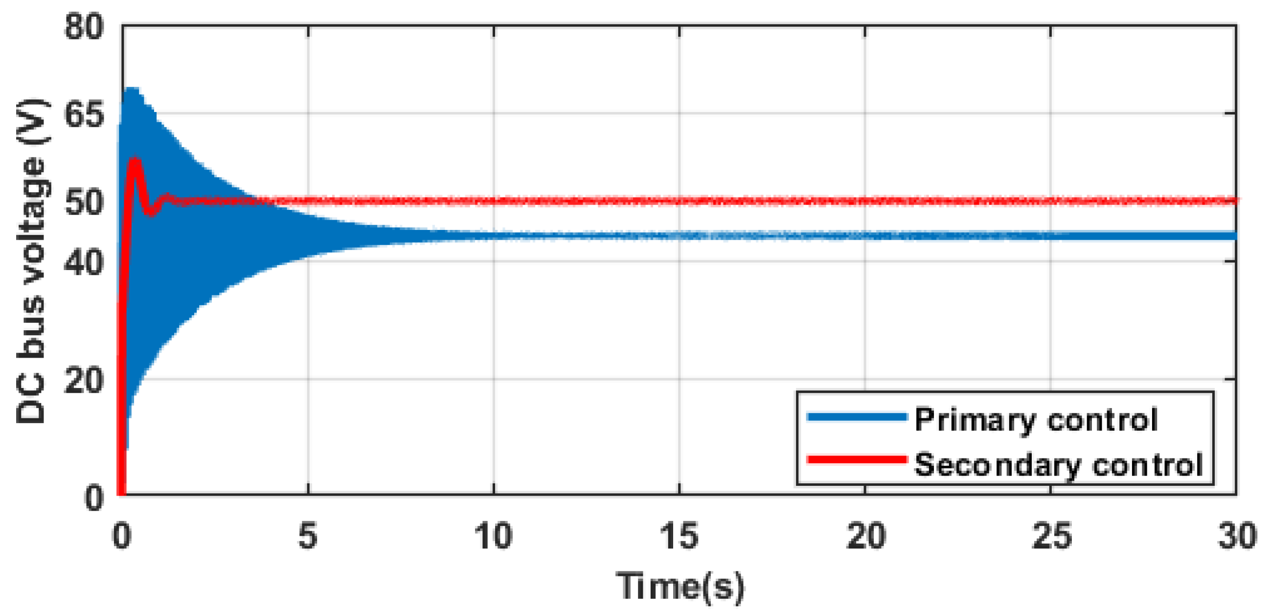
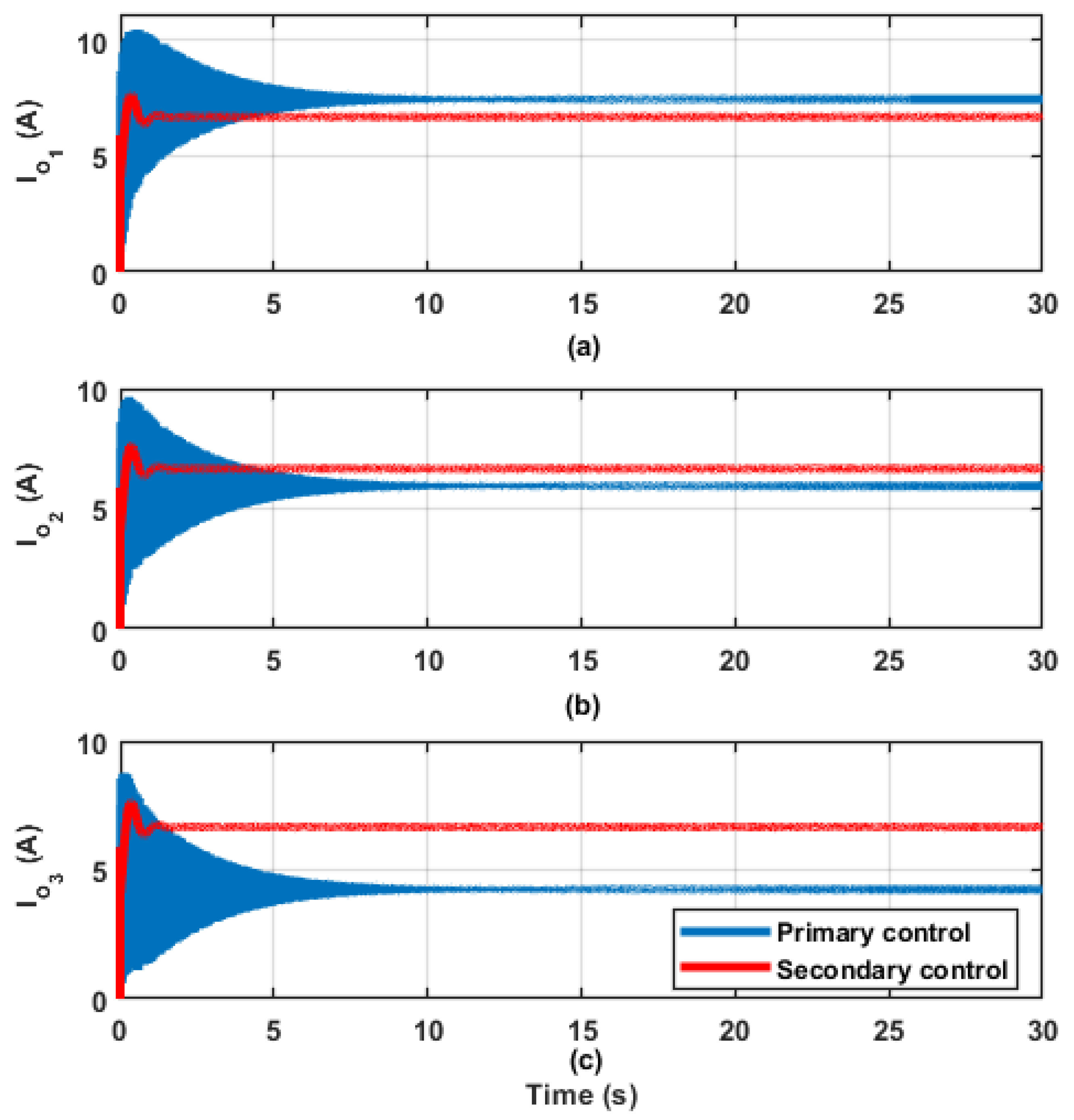
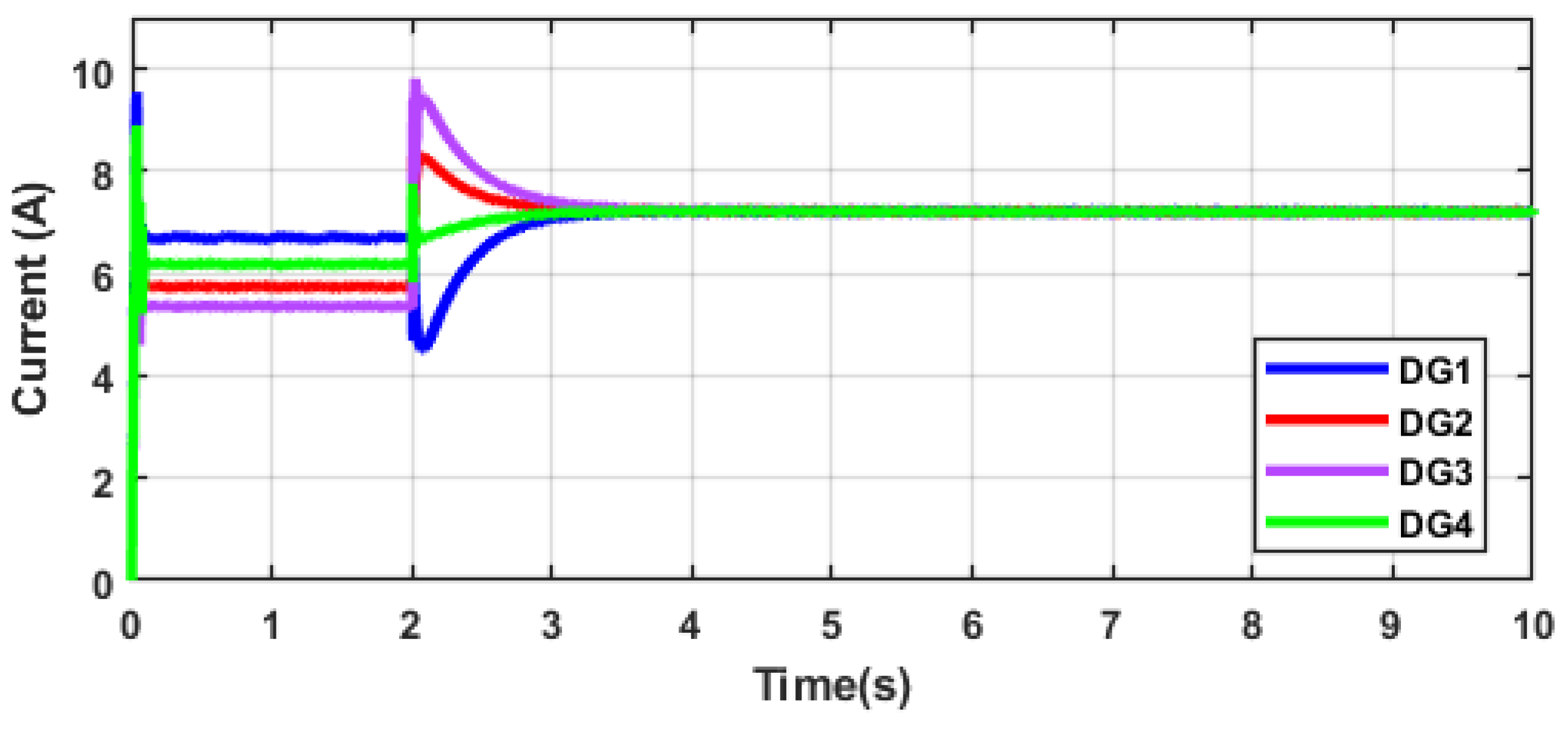
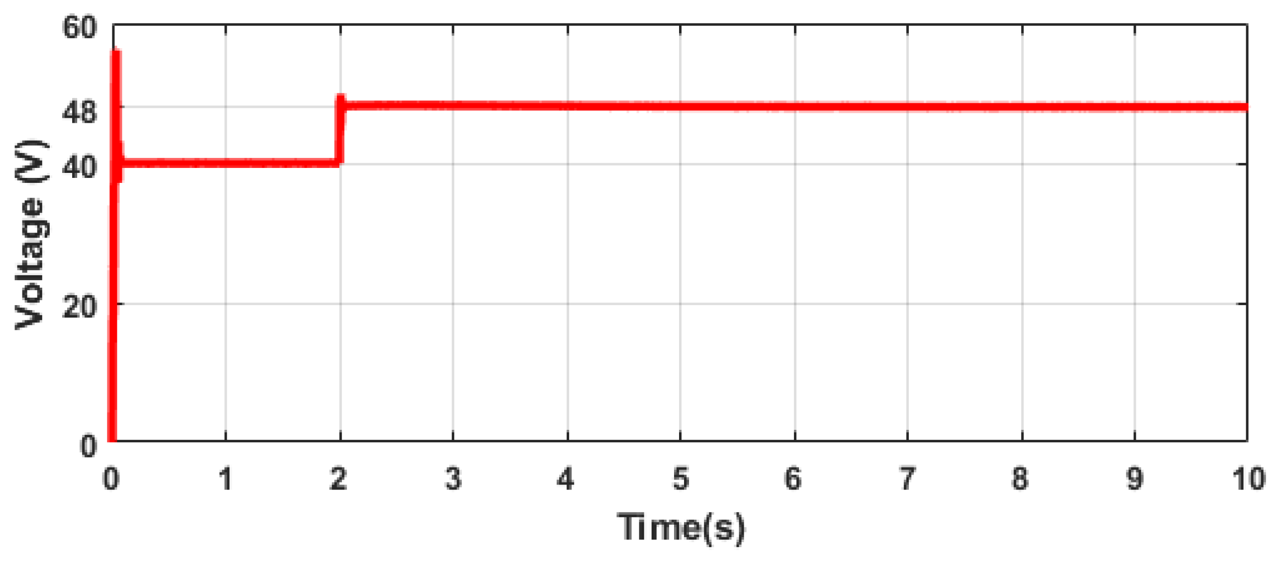
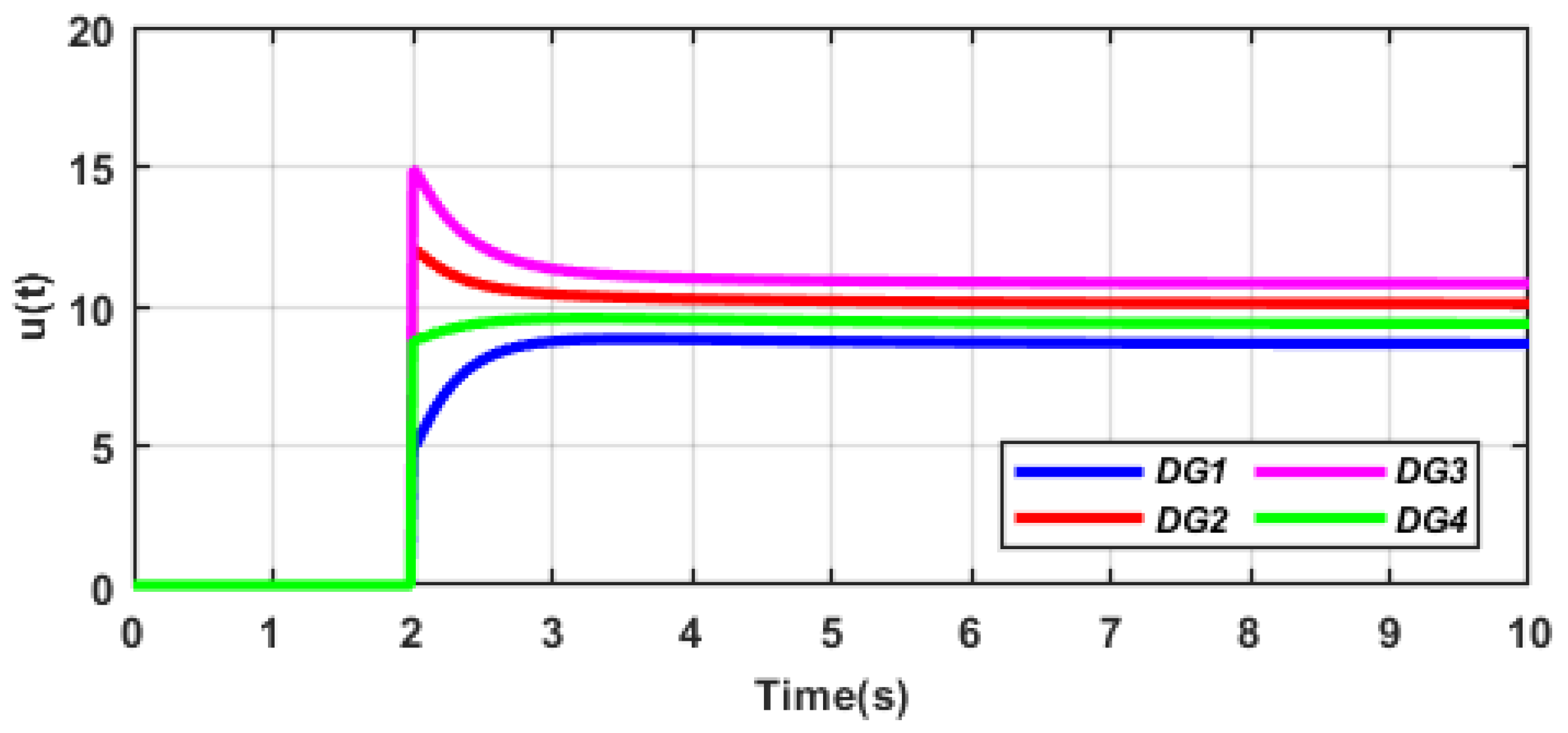
5.2. Actualization of Control Objectives by Using Proposed Optimized Distributed Secondary Control Scheme
In this scenario, the balanced current sharing and voltage regulation objectives of the proposed secondary controller by using the state–space derivation of the DC microgrid are examined. The DC microgrid operates at a reference voltage () equal to 50 V, and the DGs are modeled to share the load equally in this scenario. Figure 5 shows the plot of the bus voltage of the microgrid. It is observed that is a deviation of approximately 6 V, i.e., V when only the primary control (blue plot) of each DG is active. However, with the activation of the secondary controller, the bus voltage is regulated at the reference voltage ( V) with minimal oscillation compared to the primary controlled system. Likewise, Figure 6 shows the output current of the DGs in the microgrid. It is observed that when only the primary control loop (blue plots in Figure 6a–c) is active in each DG, it is difficult to achieve equal current sharing among the converters ( A, A, and A). With the activation of the distributed secondary controller in each DG as shown by the red plots in Figure 6a–c, the DGs achieve equal current sharing ( A) during the period of the simulation. It can be inferred that the proposed distributed secondary controller has the capability to achieve the control objectives given in (18) and (19) of the studied DC microgrid.
Figure 5.
Plot of bus voltage of DC microgrid.
Figure 6.
Plot of output current of (a) DG 1 (b) DG 2 and (c) DG 3 of the DC microgrid.
5.3. Validation by Using Real-Time Experimental Simulation
In this part, the robustness of the proposed optimized distributed secondary control is evaluated in real-time by using a detailed modeling of the microgrid. In the real-time setup, four DGs supplying two aggregated constant power loads are modeled. Individual DGs have a DC/DC buck converter with the local control embedded. The secondary control loop is designed for each DG to interact with neighboring DGs via communication links to achieve a distributed control scheme. The parameters of the detailed model are given in Table 3. In order to evaluate the performance of the proposed secondary controller; its ability to achieve the control objectives and its plug-and-play capability is investigated. The setup is developed by using MATLAB/Simulink software, and the analysis is verified by using the Speedgoat real-time digital simulator.
Table 3.
Parameters of detailed model for real-time simulation.
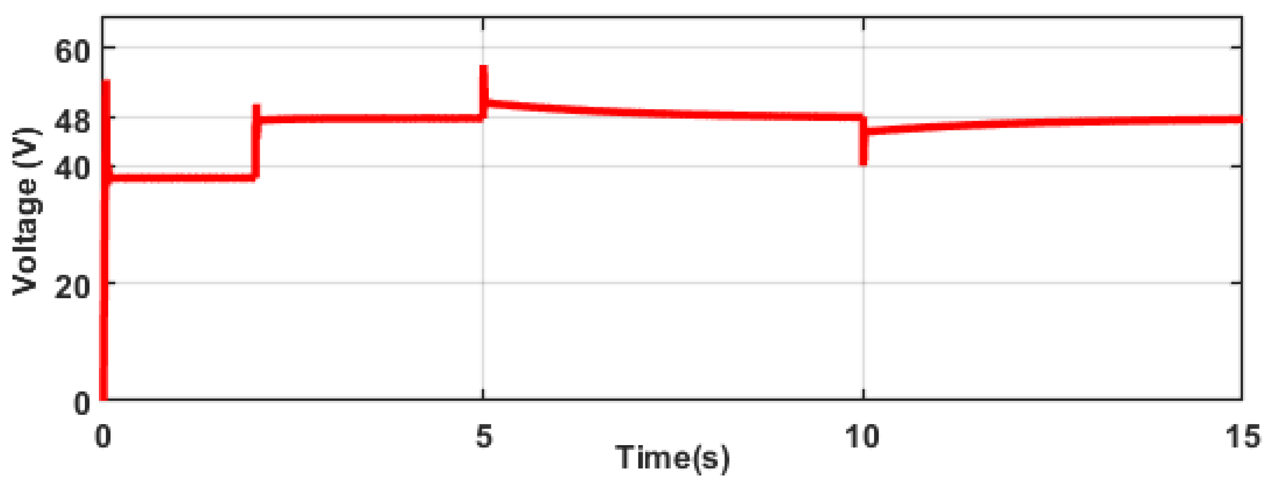
5.3.1. Current Sharing and Voltage Regulation Test
In this scenario, the voltage regulation and equal current sharing test are conducted. The voltage of the DC microgrid should be regulated at 48 V (global objective) and the distributed secondary controller allows for balanced current sharing (consensus objective) for all DGs in the microgrid. The simulation scenario is divided into two phases. In the first phase [t = 0–2 s ], only the local (primary and droop) controller in each DG is active. In the second phase [t = 2–10 s], the proposed distributed controllers in all DGs are activated. The results of this simulation are shown in Figure 7, Figure 8 and Figure 9. Figure 7 shows the voltage profile of the DC bus for the period of simulation. It is observed in the first phase that the voltage at the DC bus is 40 V; therefore, there is a deviation of 8 V from the reference voltage. However, when the proposed secondary controller is activated in the second phase, the deviation is eliminated and the DC bus voltage is regulated to its rated voltage (48 V). The output currents of the DGs are shown in Figure 8. For phase 1 (primary control), the output currents are different despite having the same current sharing ratio (1:1:1:1). In phase 2, the output currents converge to a common value 1 s after the activation of the proposed controller. It can be inferred that the control objectives are achieved when the proposed distributed secondary controller is activated at (t = 2 s) in each DG as shown in Figure 9 where the appropriate secondary control signal () is generated for each DG while interacting with neighboring DGs to achieve global voltage regulation and consensus current sharing accuracy.
Figure 7.
DC bus voltage.
Figure 8.
Output current of DGs in the microgrid.
Figure 9.
Output of proposed distributed secondary controller of each DG in the microgrid.
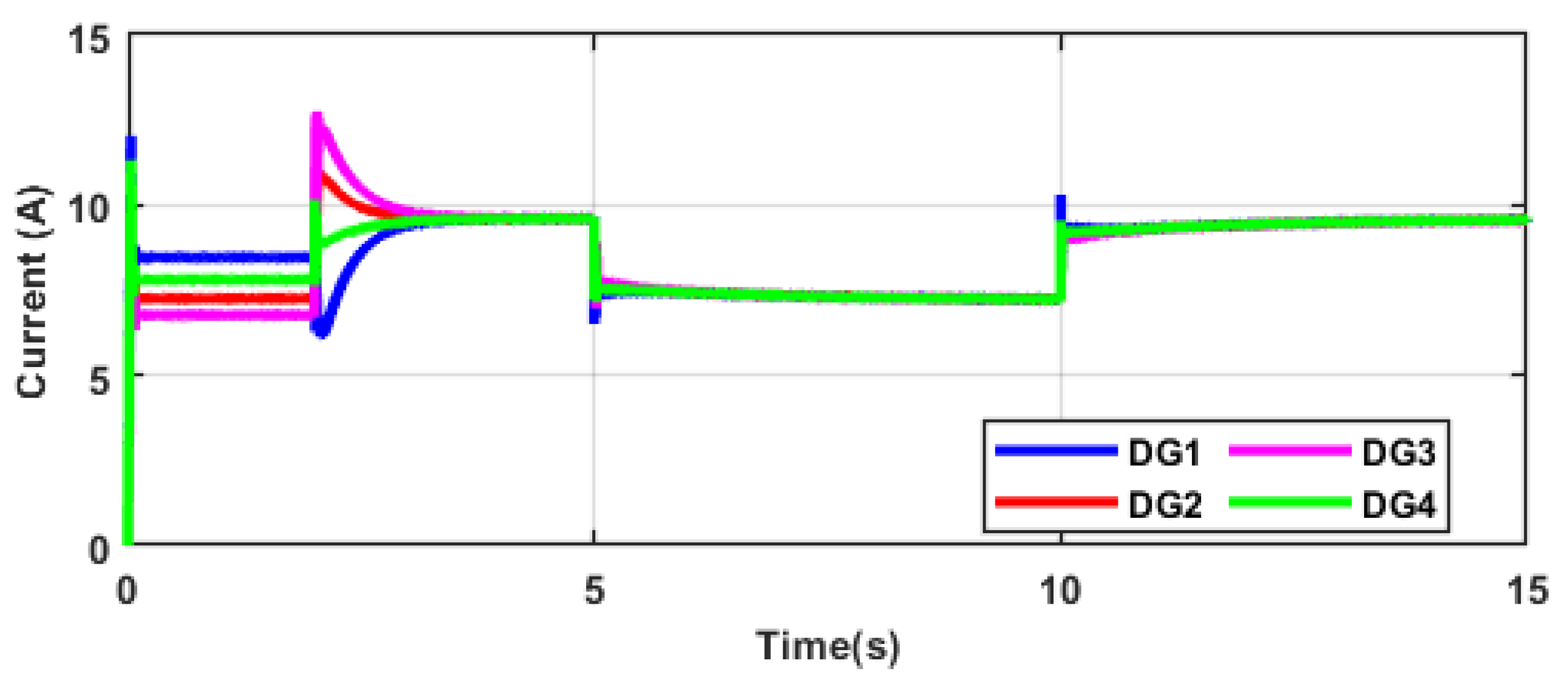
5.3.2. Distributed Property of Proposed Secondary Controller during Change in Load Scenario
In this test, another real-world scenario is examined in real-time. By using the same communication topology as in the previous test, a change in power flow is analyzed to investigate the distributed property of the proposed secondary controller. An additional load (R3) is connected and disconnected at the DC bus. The simulation period for this test is 15 s; for t = 1–2 s, only the primary control in each DG is active; for t = 2–5 s, the secondary controllers in all the DGs are activated; for t = 5–10 s, a load is connected at the DC bus; for t = 10–15 s, the load is disconnected from the DC bus. Figure 10 and Figure 11 show the voltage and current properties of the test scenario respectively. By inspecting the DC voltage in Figure 10, it is observed that there is a sudden rise in voltage when the load is connected to the DC bus. However, this transient is quickly regulated to the reference voltage (48 V) to keep the microgrid stable. Similarly, the disconnection of the load at t = 10 s causes a drop in the DC bus voltage that is restored to the reference value due to the action of the voltage control objective of the proposed secondary controller. In Figure 11, it can be observed that the balanced current sharing is achieved when the secondary controller is activated after 2 s. When the load is connected at 5 s, the output currents of the DGs drop but the DGs are able to achieve a consensus operation in real time without interfering with the communication protocol in the microgrid. Furthermore, the disconnection of the load does not alter the balanced current-sharing property of the DGs. It can be inferred that the proposed secondary controller has the capability to achieve distributed properties during changes in power flow characteristics in the microgrid without interfering with the communication topology of the microgrid setup.
Figure 10.
DC bus voltage.
Figure 11.
Output current of DGs in the microgrid.
5.4. Comparison with Other Distributed Control Schemes
Finally, the robustness of the proposed distributed secondary controller is examined by comparing its response time to achieve the control objectives with other distributed secondary controller that has been proposed in the literature. The selected control schemes have the same control objectives (current sharing and voltage regulation), but their control parameters are designed differently; the traditional secondary control (TSC)—trial and error tuning, supervisory secondary control (SSC) [27], and consensus secondary control (CSC) [28]. Table 4 presents the comparison results of the proposed control scheme and other schemes. It is observed that the SSC scheme takes 1.72 s to regulate the DC bus voltage to the reference voltage, the TSC and CSC schemes take more than 1.72 s to regulate the bus voltage. The proposed distributed control scheme has the fastest response time of less than 0.1 s when compared to the other control schemes. Likewise, the time taken to achieve a balanced current-sharing objective by the proposed controller is the least among other control schemes. It is important to mention that the voltage regulation objective is achieved in less time than the current-sharing objective because the latter requires a consensus between the DGs that involves communication among the DGs whereas the voltage regulation objective requires less communication burden.
Table 4.
Comparison of proposed control method with other control methods.
6. Conclusions
In this paper, a new distributed secondary control scheme is proposed to ensure current sharing among multiple DGs and voltage regulation in a DC microgrid. The proposed control is based on the integral control strategy and its design parameter is chosen by using the ABC optimization algorithm. The objective function of the ABC algorithm is to minimize the current-sharing error and voltage deviation in the microgrid. The proposed secondary controller is advantageous because of its simple design, implementation, and flexibility due to its tuning process. The state–space and physical models of the DC microgrid are used to test the performance of the designed controller. An eigenvalue analysis is used to ascertain the stability of the proposed secondary controller. By using the Speedgoat simulator, real-time experiments are used to verify the robustness of the proposed distributed secondary controller to achieve the control objectives of the DC microgrid. The results show that the proposed distributed controller can achieve accurate current sharing and voltage regulation in a stand-alone DC microgrid with a faster response time when compared to classical controllers. This research will be extended to nonlinear characteristics in a DC microgrid.
Author Contributions
Conceptualization, A.A. and A.S.; methodology, A.A.; software, A.S. and L.J.; validation, A.A. and A.S.; formal analysis, A.A.; writing—original draft preparation, A.A.; writing—review and editing, A.S. and D.D.; supervision, A.S., L.J. and D.D.; funding acquisition, A.S., L.J. and D.D. All authors have read and agreed to the published version of the manuscript.
Funding
This project is funded by the Center for Power and Energy Systems at the University of KwaZulu-Natal, South Africa.
Institutional Review Board Statement
Not applicable.
Informed Consent Statement
Not applicable.
Data Availability Statement
Not applicable.
Conflicts of Interest
The authors declare no conflict of interest.
References
- Dragičević, T.; Lu, X.; Vasquez, J.C.; Guerrero, J.M. DC microgrids—Part I: A review of control strategies and stabilization techniques. IEEE Trans. Power Electron. 2015, 31, 4876–4891. [Google Scholar]
- Aluko, A.; Musumpuka, R.; Dorrell, D. Cyberattack-Resilient Secondary Frequency Control Scheme for Stand-Alone Microgrids. IEEE Trans. Ind. Electron. 2022, 1. [Google Scholar] [CrossRef]
- Xia, Y.; Wei, W.; Peng, Y.; Yang, P.; Yu, M. Decentralized coordination control for parallel bidirectional power converters in a grid-connected DC microgrid. IEEE Trans. Smart Grid 2017, 9, 6850–6861. [Google Scholar] [CrossRef]
- Shan, Y.; Hu, J.; Chan, K.W.; Islam, S. A unified model predictive voltage and current control for microgrids with distributed fuzzy cooperative secondary control. IEEE Trans. Ind. Inform. 2021, 17, 8024–8034. [Google Scholar] [CrossRef]
- Hamad, A.A.; Azzouz, M.A.; El-Saadany, E.F. Multiagent supervisory control for power management in DC microgrids. IEEE Trans. Smart Grid 2016, 7, 1057–1068. [Google Scholar] [CrossRef]
- Anand, S.; Fernandes, B. Optimal voltage level for DC microgrids. In Proceedings of the IECON 2010-36th Annual Conference on IEEE Industrial Electronics Society, Glendale, AZ, USA, 7–10 November 2010; pp. 3034–3039. [Google Scholar]
- Al-Ismail, F.S. DC microgrid planning, operation, and control: A comprehensive review. IEEE Access 2021, 9, 36154–36172. [Google Scholar] [CrossRef]
- Gao, L.; Liu, Y.; Ren, H.; Guerrero, J.M. A DC microgrid coordinated control strategy based on integrator current-sharing. Energies 2017, 10, 1116. [Google Scholar] [CrossRef] [Green Version]
- Papadimitriou, C.; Zountouridou, E.; Hatziargyriou, N. Review of hierarchical control in DC microgrids. Electr. Power Syst. Res. 2015, 122, 159–167. [Google Scholar] [CrossRef]
- Thomas, V.; Kumaravel, S.; Ashok, S. Control of parallel DC-DC converters in a DC microgrid using virtual output impedance method. In Proceedings of the 2016 2nd International Conference on Advances in Electrical, Electronics, Information, Communication and Bio-Informatics (AEEICB), Chennai, India, 27–28 February 2016; pp. 587–591. [Google Scholar]
- Mokhtar, M.; Marei, M.I.; El-Sattar, A.A. An adaptive droop control scheme for DC microgrids integrating sliding mode voltage and current controlled boost converters. IEEE Trans. Smart Grid 2017, 10, 1685–1693. [Google Scholar] [CrossRef]
- Yang, Q.; Jiang, L.; Zhao, H.; Zeng, H. Autonomous voltage regulation and current sharing in islanded multi-inverter DC microgrid. IEEE Trans. Smart Grid 2018, 9, 6429–6437. [Google Scholar] [CrossRef]
- Peyghami, S.; Mokhtari, H.; Davari, P.; Loh, P.C.; Blaabjerg, F. On secondary control approaches for voltage regulation in DC microgrids. IEEE Trans. Ind. Appl. 2017, 53, 4855–4862. [Google Scholar] [CrossRef] [Green Version]
- Liu, G.; Caldognetto, T.; Mattavelli, P.; Magnone, P. Power-based droop control in dc microgrids enabling seamless disconnection from upstream grids. IEEE Trans. Power Electron. 2019, 34, 2039–2051. [Google Scholar] [CrossRef] [Green Version]
- Yang, J.; Jin, X.; Wu, X.; Acuna, P.; Aguilera, R.P.; Morstyn, T.; Agelidis, V.G. Decentralised control method for DC microgrids with improved current sharing accuracy. IET Gener. Transm. Distrib. 2017, 11, 696–706. [Google Scholar] [CrossRef]
- Nahata, P.; La Bella, A.; Scattolini, R.; Ferrari-Trecate, G. Hierarchical control in islanded DC microgrids with flexible structures. IEEE Trans. Control. Syst. Technol. 2020, 29, 2379–2392. [Google Scholar] [CrossRef]
- Guo, F.; Xu, Q.; Wen, C.; Wang, L.; Wang, P. Distributed secondary control for power allocation and voltage restoration in islanded DC microgrids. IEEE Trans. Sustain. Energy 2018, 9, 1857–1869. [Google Scholar] [CrossRef]
- Guo, F.; Wang, L.; Wen, C.; Zhang, D.; Xu, Q. Distributed voltage restoration and current sharing control in islanded DC microgrid systems without continuous communication. IEEE Trans. Ind. Electron. 2020, 67, 3043–3053. [Google Scholar] [CrossRef]
- Sahoo, S.; Mishra, S. A distributed finite-time secondary average voltage regulation and current sharing controller for DC microgrids. IEEE Trans. Smart Grid 2018, 10, 282–292. [Google Scholar] [CrossRef]
- Liu, X.K.; He, H.; Wang, Y.W.; Xu, Q.; Guo, F. Distributed hybrid secondary control for a DC microgrid via discrete-time interaction. IEEE Trans. Energy Convers. 2018, 33, 1865–1875. [Google Scholar] [CrossRef]
- Liu, X.K.; Jiang, H.; Wang, Y.W.; He, H. A distributed iterative learning framework for DC microgrids: Current sharing and voltage regulation. IEEE Trans. Emerg. Top. Comput. Intell. 2020, 4, 119–129. [Google Scholar] [CrossRef]
- Aluko, A.O.; Carpanen, R.P.; Dorrell, D.G.; Ojo, E.E. Impact Assessment and Mitigation of Cyber Attacks on Frequency Stability of Isolated Microgrid Using Virtual Inertia Control. In Proceedings of the 2020 IEEE PES/IAS PowerAfrica, Virtual Event, 25–28 August 2020; pp. 1–5. [Google Scholar]
- Aluko, A.O.; Dorrell, D.G.; Pillay Carpanen, R.; Ojo, E.E. Heuristic Optimization of Virtual Inertia Control in Grid-Connected Wind Energy Conversion Systems for Frequency Support in a Restructured Environment. Energies 2020, 13, 564. [Google Scholar] [CrossRef] [Green Version]
- Aluko, A.O.; Dorrell, D.G.; Carpanen, R.P.; Ojo, E.E. Heuristic Secondary Frequency Control of AC/DC Interconnected Power System in a Deregulated Environment. In Proceedings of the 2020 International SAUPEC/RobMech/PRASA Conference, Cape Town, South Africa, 29–31 January 2020; pp. 1–6. [Google Scholar] [CrossRef]
- Yang, X.S.; Deb, S. Multiobjective cuckoo search for design optimization. Comput. Oper. Res. 2013, 40, 1616–1624. [Google Scholar] [CrossRef]
- Ghanbari, N.; Bhattacharya, S.; Mobarrez, M. Modeling and stability analysis of a dc microgrid employing distributed control algorithm. In Proceedings of the 2018 9th IEEE International Symposium on Power Electronics for Distributed Generation Systems (PEDG), Charlotte, NC, USA, 25–28 June 2018; pp. 1–7. [Google Scholar]
- Liu, X.K.; Wang, Y.W.; Lin, P.; Wang, P. Distributed supervisory secondary control for a DC microgrid. IEEE Trans. Energy Convers. 2020, 35, 1736–1746. [Google Scholar] [CrossRef]
- Dong, M.; Li, L.; Nie, Y.; Song, D.; Yang, J. Stability analysis of a novel distributed secondary control considering communication delay in DC microgrids. IEEE Trans. Smart Grid 2019, 10, 6690–6700. [Google Scholar] [CrossRef]
Publisher’s Note: MDPI stays neutral with regard to jurisdictional claims in published maps and institutional affiliations. |
© 2022 by the authors. Licensee MDPI, Basel, Switzerland. This article is an open access article distributed under the terms and conditions of the Creative Commons Attribution (CC BY) license (https://creativecommons.org/licenses/by/4.0/).