
A Smart Microgrid System with Artificial Intelligence for Power-Sharing and Power Quality Improvement


Abstract
:1. Introduction
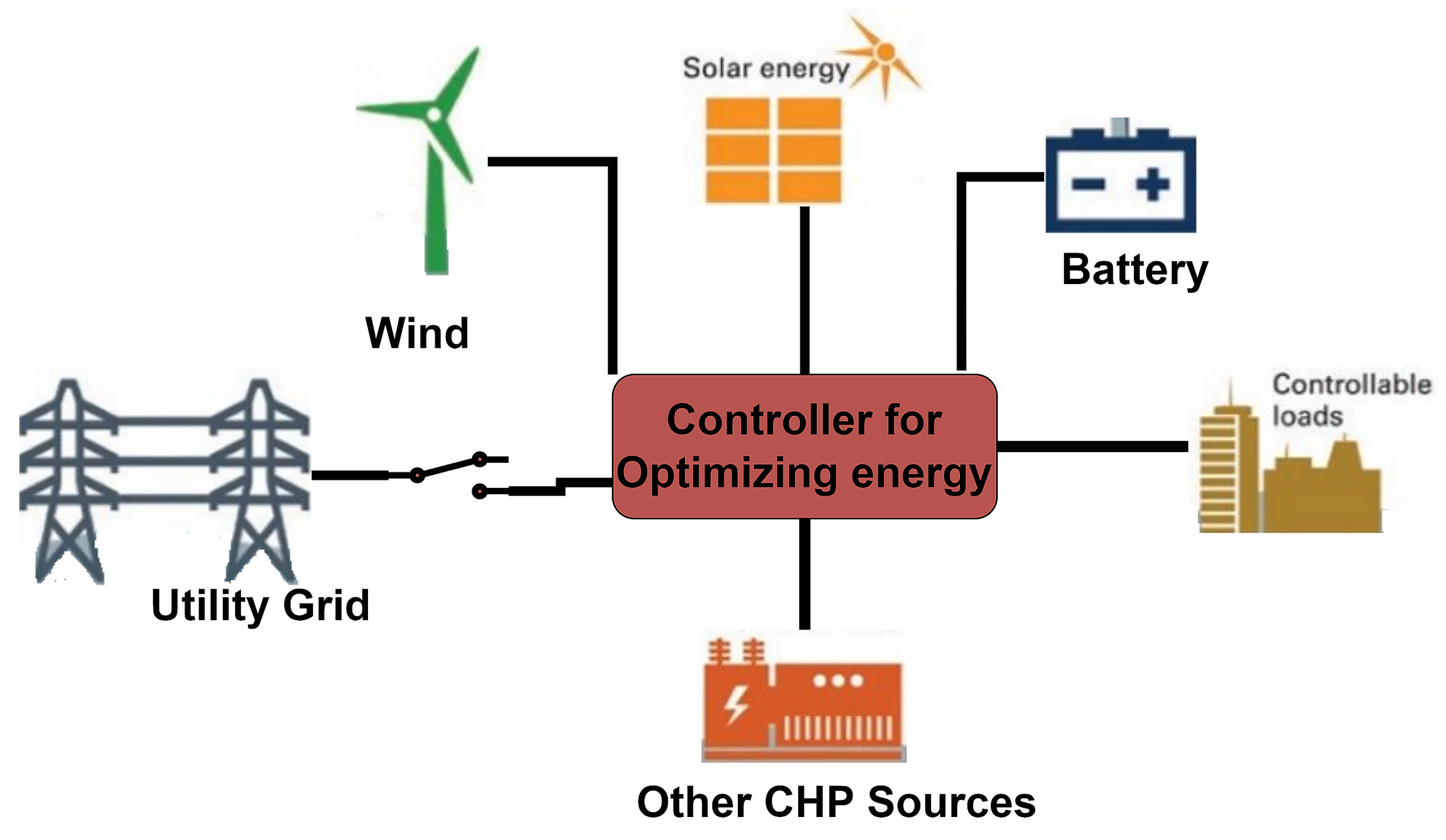
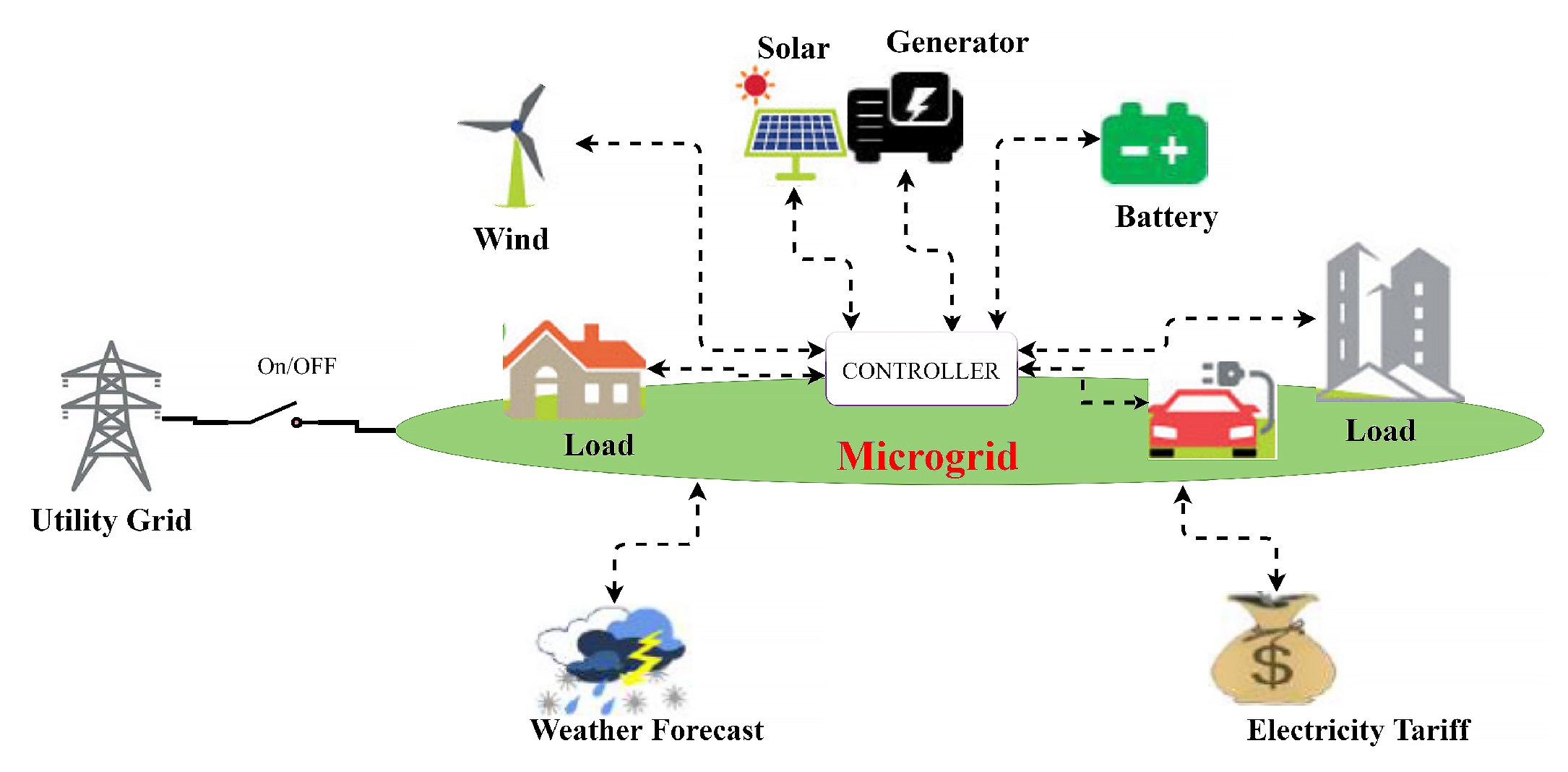
1.1. Smart Microgrid
1.2. Smart Microgrid Systems
2. Materials and Methods
2.1. Proposed Smart Grid System with Multiple Smart Microgrids Coupled with RES
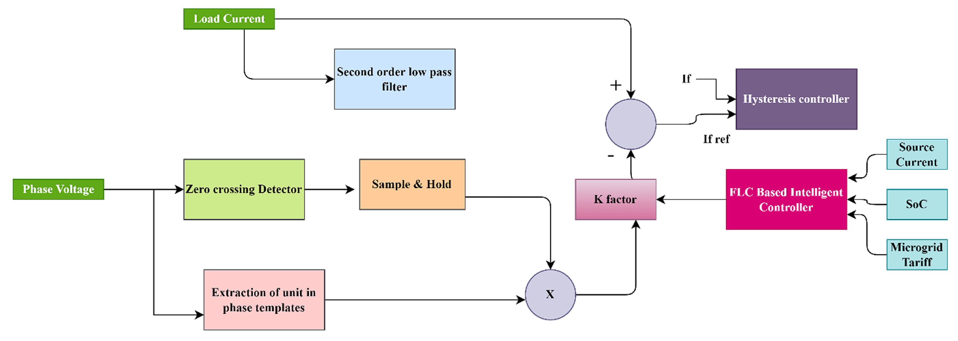
2.2. Proposed AI-Based Icos Control Algorithm for Power Sharing and Power Quality Improvement in Smart Microgrid System
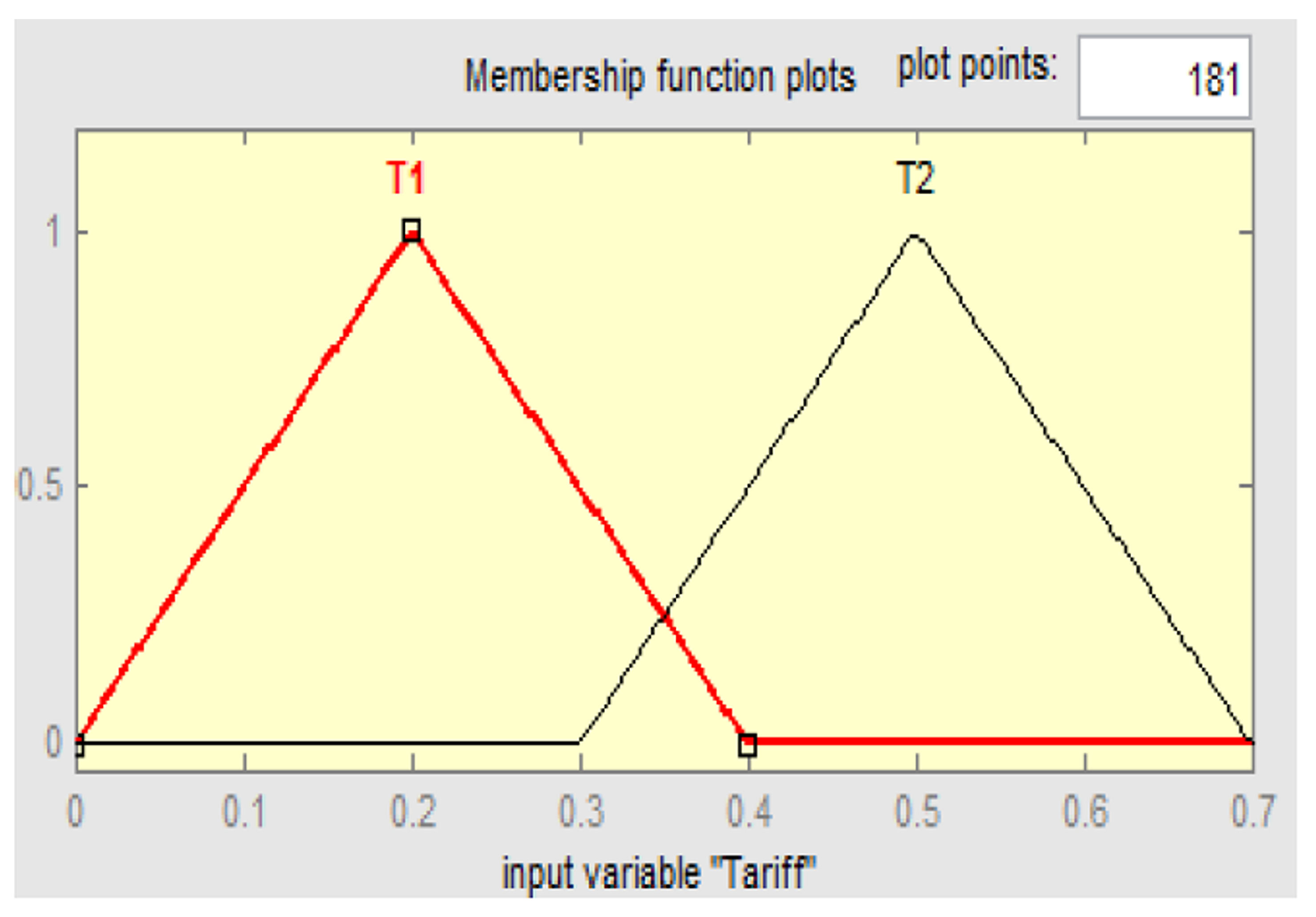
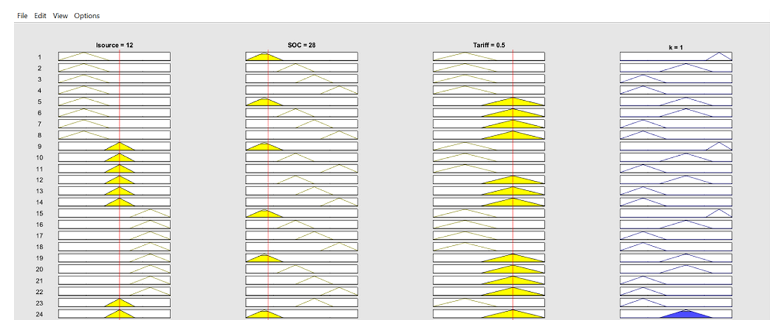
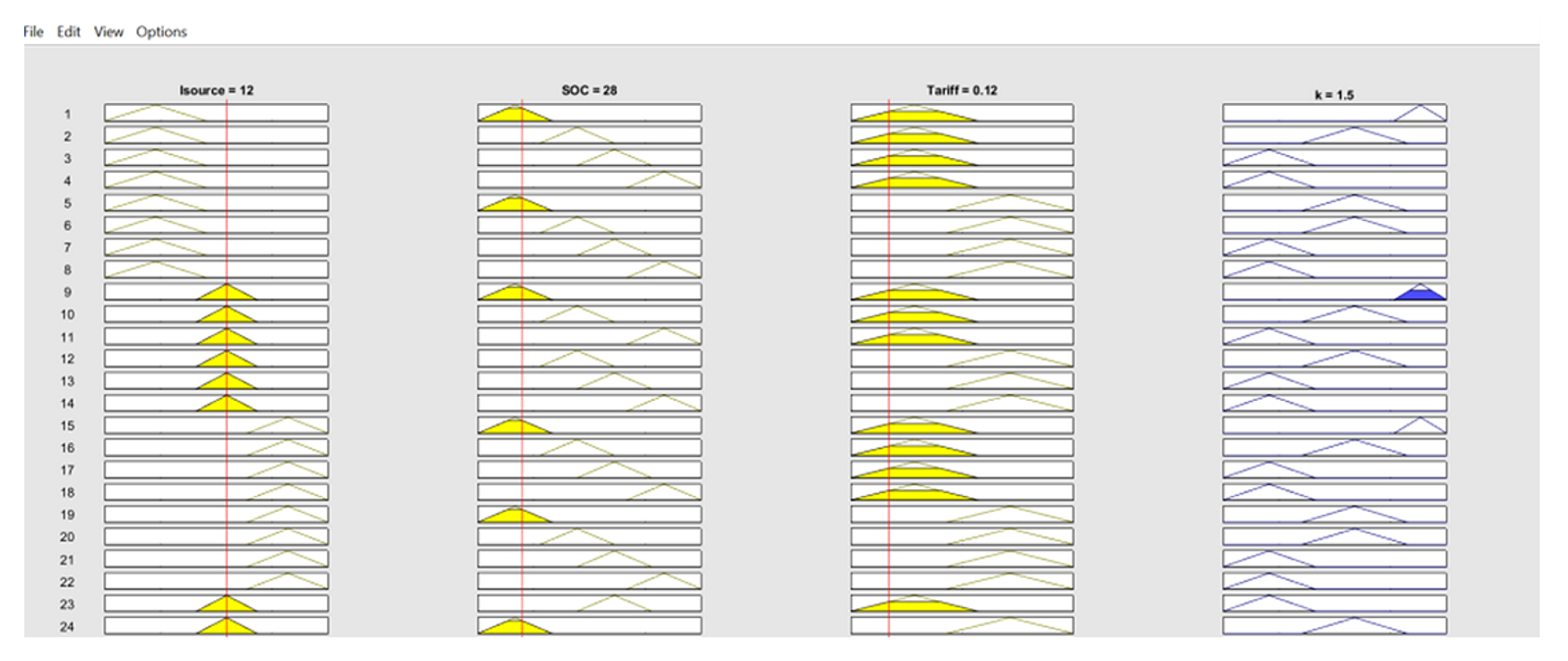
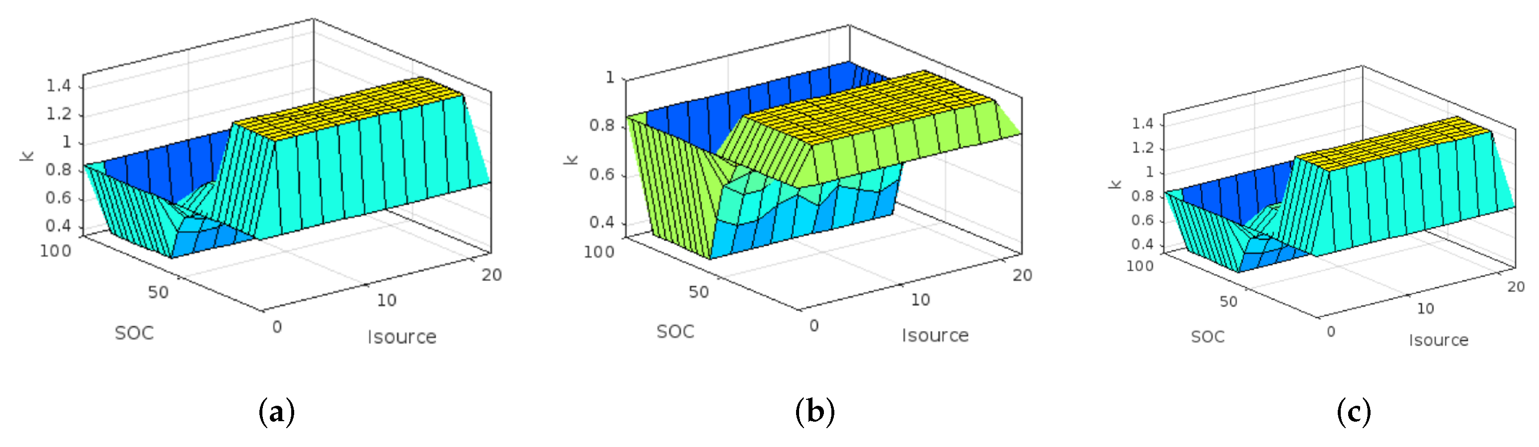
2.3. Intelligent Integrated Controller for Smart Microgrid Using FLC
3. Results
3.1. Design Verification of Proposed Smart Microgrid System Using Intelligent Integrated FLC
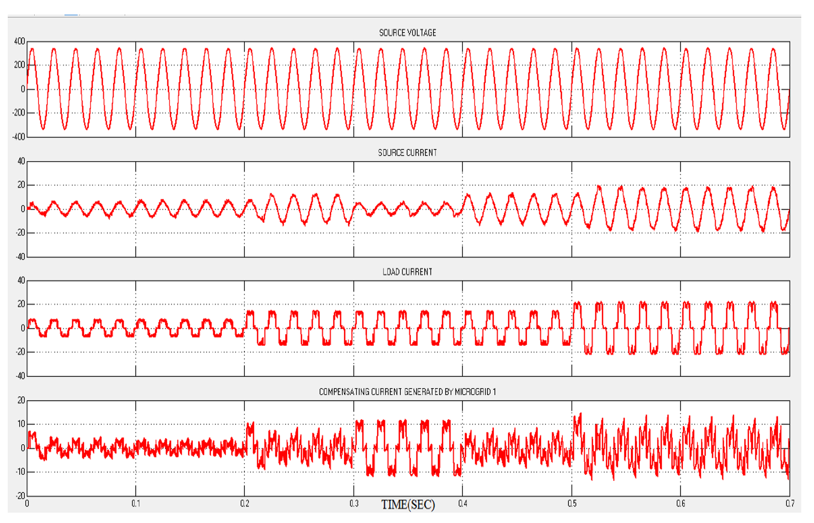
3.1.1. Simulation Model of the Proposed System with Unbalanced Non-Linear Load
3.2. Tariff Controller and Power Flow Management of the Smart Microgrid System
3.3. Hardware Implementation of the Proposed Intelligent Integrated FLC
4. Discussion
Economic Feasibility of the Proposed Smart Microgrid Model
5. Conclusions
Author Contributions
Funding
Institutional Review Board Statement
Informed Consent Statement
Data Availability Statement
Conflicts of Interest
Abbreviations
| DC | Direct Current |
| AC | Alternating Current |
| PV | Photovoltaic |
| SAF | Shunt Active Filters |
| IRPT | Instantaneous Reactive Power Theory |
| SRFT | Synchronous Reference Frame Theory |
| ILST | Improved Linear Sinusoidal Tracer |
| IRENA | International Renewable Energy Agency |
| RES | Renewable Energy source |
| MG | Microgrids |
| AI | Artificial Intelligence |
| FLC | Fuzzy Logic Controller |
| PI | Proportional Integral |
| IIC | Intelligent Integrated Controller |
| PCC | Point of Common Coupling |
| SoC | State of Charge |
| FFT | Fast Fourier Transform |
| THD | Total Harmonic Distortion |
| DG | Distributed Generation |
| CBA | Cost Benefit Analysis |
References
- Majid, M.A. Renewable energy for sustainable development in India: Current status, future prospects, challenges, employment, and investment opportunities. Energy Sustain. Soc. 2020, 10, 2. [Google Scholar]
- Campagna, N.; Caruso, M.; Castiglia, V.; Miceli, R.; Viola, F. Energy management concepts for the evolution of smart grids. In Proceedings of the 2020 8th IEEE International Conference on Smart Grid (icSmartGrid), Paris, France, 17–19 June 2020; pp. 208–213. [Google Scholar]
- Beres, R.N.; Wang, X.; Liserre, M.; Blaabjerg, F.; Bak, C.L. A Review of Passive Power Filters for Three-Phase Grid-Connected Voltage-Source Converters. IEEE J. Emerg. Sel. Top. Power Electron. 2016, 4, 54–69. [Google Scholar] [CrossRef] [Green Version]
- Novas, N.; Alcayde, A.; Robalo, I.; Manzano-Agugliaro, F.; Montoya, F.G. Energies and Its Worldwide Research. Energies 2020, 13, 6700. [Google Scholar] [CrossRef]
- Revuelta, P.S.; Litrán, S.P.; Thomas, J.P. Active Power Line Conditioners: Design, Simulation and Implementation for Improving Power Quality; Academic Press: Cambridge, MA, USA, 2015; pp. 107–190. [Google Scholar]
- Revuelta, P.S.; Litrán, S.P.; Thomas, J.P. Instantaneous Reactive Power Theory. Act. Power Line Cond. 2016, 51–120. [Google Scholar]
- Lipo, T.A. Reference Frame Theory. Anal. Synchronous Mach. 2017, 77–135. [Google Scholar] [CrossRef]
- Bhuvaneswari, G.; Nair, M.G. Design, Simulation, and Analog Circuit Implementation of a Three-Phase Shunt Active Filter Using the IcosΦ Algorithm. IEEE Trans. Power Deliv. 2008, 23, 1222–1235. [Google Scholar] [CrossRef]
- Singh, B.; Arya, S.R. Adaptive Theory-Based Improved Linear Sinusoidal Tracer Control Algorithm for DSTATCOM. IEEE Trans. Power Electron. 2013, 28, 3768–3778. [Google Scholar] [CrossRef]
- Halpin, S.M.; Card, A. Power Quality. In Power Electronics Handbook; 2011; pp. 1179–1192. Available online: https://www.sciencedirect.com/science/article/pii/B9780123820365000409 (accessed on 1 January 2020).
- IRENA Renewable Capacity Statistics 2018. The International Renewable Agency, Madsar City, UAE. Available online: https://www.irena.org/publications/2018/Mar/Renewable-Capacity-Statistics (accessed on 20 March 2018).
- Tavakoli, A.; Saha, S.; Arif, M.T.; Haque, M.E.; Mendis, N.; Oo, A.M.T. Impacts of grid integration of solar PV and electric vehicle on grid stability, power quality and energy economics: A review. IET Energy Syst. Integr. 2020, 2, 243–260. [Google Scholar] [CrossRef]
- Soonee, S.K.; Saxena, S.C.; Baba, K.V.S.; Narasimhan, S.R.; Kumar, K.V.N.P.; Agarwal, P.K.; Batra, P.; Mukhopadhyay, S. Renewable Energy Integration in India: Present State and Long-Term Perspective. In Proceedings of the 2019 IEEE Milan PowerTech, Milan, Italy, 23–27 June 2019. [Google Scholar]
- Dobriansky, L.; Ghatikar, G.; Ton, D. Smart Microgrids: Re-visioning Smart Grid and Smart City Development in India. In ISGW 2017: Compendium of Technical Papers, Proceedings of the 3rd International Conference and Exhibition on Smart Grids and Smart Cities, New Delhi, India, 7–10 March 2017; Lecture Notes in Electrical Engineering; Springer: Singapore, 2018; pp. 273–288. [Google Scholar]
- Alsaidan, I.; Chaudhary, P.; Alaraj, M.; Rizwan, M. An intelligent approach to active and reactive power control in a grid-connected solar photovoltaic system. Sustainability 2021, 13, 4219. [Google Scholar] [CrossRef]
- Boujoudar, Y.; Azeroual, M.; El Moussaoui, H.; Lamhamdi, T. Intelligent controller based energy management for stand-alone power system using artificial neural network. Int. Trans. Electr. Energy Syst. 2020, 30, e12579. [Google Scholar] [CrossRef]
- Shareef, H.; Ahmed, M.S.; Mohamed, A.; Al Hassan, E. Review on home energy management system considering demand responses, smart technologies, and intelligent controllers. IEEE Access 2018, 6, 24498–24509. [Google Scholar] [CrossRef]
- Roy, J.N.; Bose, D.N. Design and Implementation of Off-Grid and On-Grid SPV Systems. In Photovoltaic Science and Technology; Cambridge University Press: Cambridge, UK, 2018; pp. 358–400. [Google Scholar]
- Sharma, A.; Kolhe, M.L. Impacts of electricity pricing on techno-economic performance of photovoltaic-battery centered microgrid. Energy Sources Part A Recover. Util. Environ. Eff. 2021, 1–16. [Google Scholar] [CrossRef]
- Nair, D.R.; Devi, S.; Nair, M.G.; Ilango, K. Tariff based fuzzy logic controller for active power sharing between microgrid to grid with improved power quality. In Proceedings of the 2016 International Conference on Energy Efficient Technologies for Sustainability (ICEETS), Nagercoil, India, 7–8 April 2016. [Google Scholar]
- Preetha, P.K.; Babu, S.S.; Nair, M.G. DC link voltage regulation in active filter using drainage power from distribution transformer. In Proceedings of the 2016 IEEE 1st International Conference on Power Electronics, Intelligent Control and Energy Systems (ICPEICES), Delhi, India, 4–6 July 2016. [Google Scholar]
- Gauthami, R.; Nair, V.V.; Sathish, A.; Soureesh, K.V.; Ilango, K.; Sreelekshmi, R.S.; Ilangovan, S.A.; Sujatha, S. Design and Implementation of Efficient Energy Management System in Electric Vehicles. In Innovations in Electrical and Electronics Engineering; Lecture Notes in Electrical Engineering 626; Springer: Singapore, 2020; pp. 543–559. [Google Scholar] [CrossRef]
- Stanly, L.S.; Divya, R.; Nair, M.G. Grid connected solar photovoltaic system with Shunt Active Filtering capability under transient load conditions. In Proceedings of the 2015 International Conference on Technological Advancements in Power and Energy (TAP Energy), Kollam, India, 24–26 June 2015. [Google Scholar]
- Niharika, R.; Pavan, K.M.S.; Manitha, P.V. Development of Fast charging system with ZVS integrated with Fuzzy controller-based Hybrid renewable energy source. J. Phys. Conf. Ser. 2021, 2070, 012117. [Google Scholar] [CrossRef]
- Gupta, S. Use of triangular membership function for prediction of compressive strength of concrete containing Nano silica. Cogent Eng. 2015, 2, 1025578. [Google Scholar] [CrossRef]
- Ab-BelKhair, A.; Rahebi, J.; Nureddin, A.A.M. A Study of Deep Neural Network Controller-Based Power Quality Improvement of Hybrid PV/Wind Systems by Using Smart Inverter. Int. J. Photoenergy 2020, 2020, 8891469. [Google Scholar] [CrossRef]
- Sinha, S.; Tekumalla, D.V.; Bajpai, P. Fuzzy Logic Controlled Power Sharing among Energy Storage Devices in Multiple Standalone DC Microgrids. In Proceedings of the 2019 IEEE PES Innovative Smart Grid Technologies Europe (ISGT-Europe), Bucharest, Romania, 29 September–2 October 2019; pp. 1–5. [Google Scholar]
- Arcos-Aviles, D.; Pascual, J.; Marroyo, L.; Sanchis, P.; Guinjoan, F. Fuzzy Logic-Based Energy Management System Design for Residential Grid-Connected Microgrids. IEEE Trans. Smart Grid 2018, 9, 530–543. [Google Scholar] [CrossRef] [Green Version]
- Padmini, V.; Omran, S.; Chatterjee, K.; Khaparde, S.A. Cost benefit analysis of smart grid: A case study from India. In Proceedings of the 2017 North American Power Symposium (NAPS), Morgantown, WV, USA, 17–19 September 2017; pp. 1–6. [Google Scholar]


| Source Current | Range |
|---|---|
| I1 | 0–5–10 |
| I2 | 9–12–15 |
| I3 | 14–18–22 |
| SoC | Range |
|---|---|
| S1 (very low) | 10–25–40 |
| S2 (low) | 35–50–65 |
| S3 (medium) | 50–65–80 |
| S4 (high) | 70–85–100 |
| Tariff | Range |
|---|---|
| T1 | 0–0.2–0.4 |
| T2 | 0.3–0.5–0.7 |
| Gain Factor (K) | Range |
|---|---|
| k1 | 0–0.35–0.7 |
| k2 | 0.6–1–1.4 |
| k3 | 1.3–1.5–1.7 |
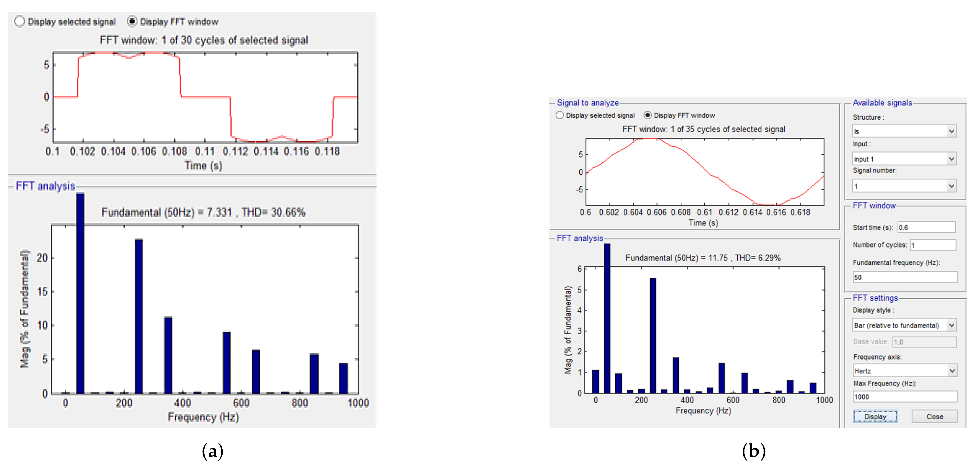
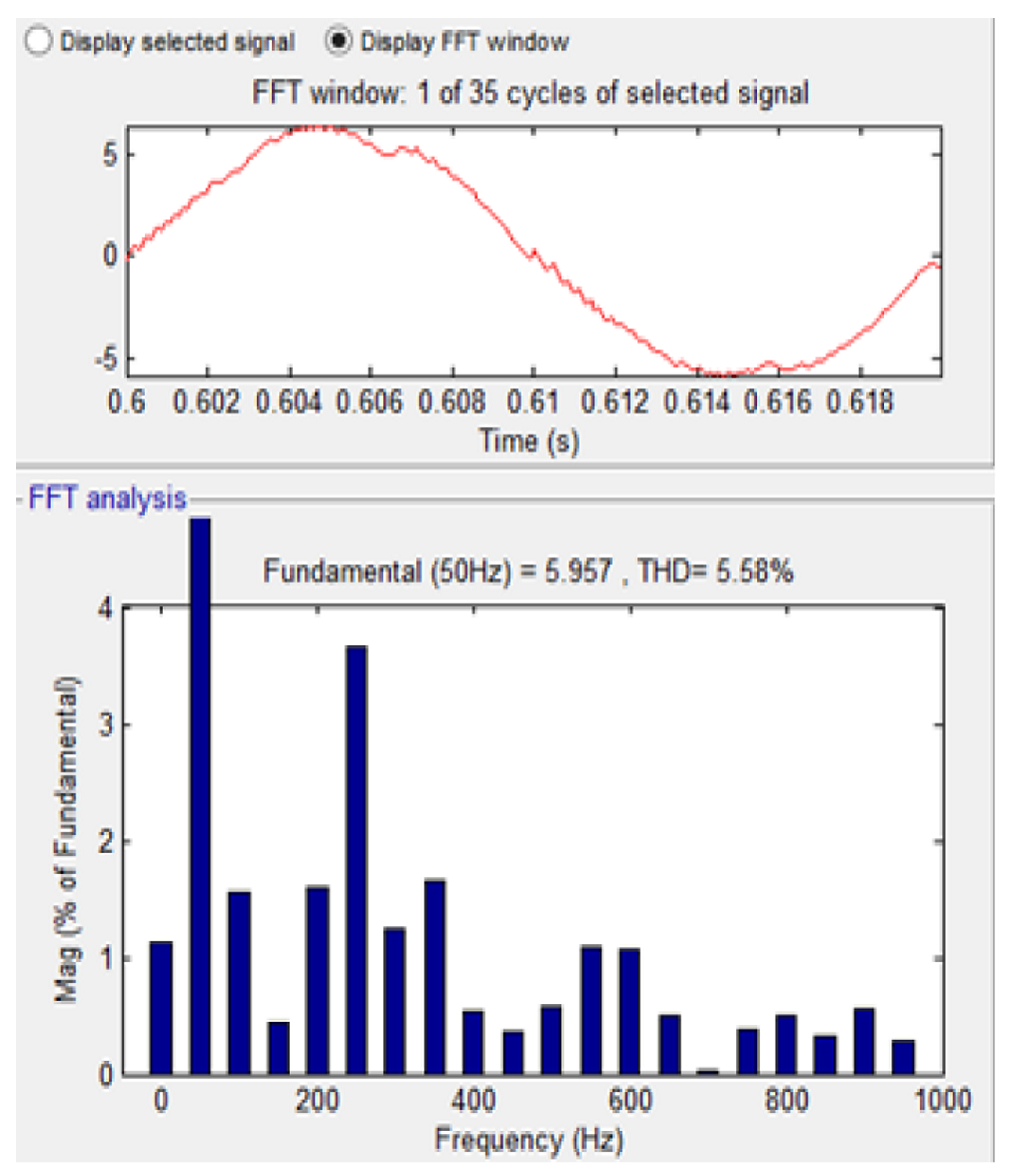
| System | THD |
|---|---|
| THD of uncompensated system | 30.66% |
| THD of smart microgrid system with MG1 integrated to the grid with IIC. | 6.29% |
| THD of smart microgrid system with MG1 and MG2 integrated to the grid with IIC. | 5.59% |
| THD of smart microgrid system with MG1 and MG2 integrated to the grid with IIC at different tariffs. | 4.92% |
| THD of smart microgrid system with MG1 and MG2 integrated to the grid with IIC at equal tariffs. | 3.64% |
Publisher’s Note: MDPI stays neutral with regard to jurisdictional claims in published maps and institutional affiliations. |
© 2022 by the authors. Licensee MDPI, Basel, Switzerland. This article is an open access article distributed under the terms and conditions of the Creative Commons Attribution (CC BY) license (https://creativecommons.org/licenses/by/4.0/).
Share and Cite
Nair, D.R.; Nair, M.G.; Thakur, T. A Smart Microgrid System with Artificial Intelligence for Power-Sharing and Power Quality Improvement. Energies 2022, 15, 5409. https://doi.org/10.3390/en15155409
Nair DR, Nair MG, Thakur T. A Smart Microgrid System with Artificial Intelligence for Power-Sharing and Power Quality Improvement. Energies. 2022; 15(15):5409. https://doi.org/10.3390/en15155409
Chicago/Turabian StyleNair, Divya R., Manjula G. Nair, and Tripta Thakur. 2022. "A Smart Microgrid System with Artificial Intelligence for Power-Sharing and Power Quality Improvement" Energies 15, no. 15: 5409. https://doi.org/10.3390/en15155409
APA StyleNair, D. R., Nair, M. G., & Thakur, T. (2022). A Smart Microgrid System with Artificial Intelligence for Power-Sharing and Power Quality Improvement. Energies, 15(15), 5409. https://doi.org/10.3390/en15155409