Abstract
Ventilation of an indoor swimming pool is a very energy consuming process. This is a result of, among other things the required high value of the ventilation air volume flow rate, calculated on the basis of the moisture gains in the facility. The total energy consumption consists of the heat required to heat this air and the electricity needed to transport it. It is possible to reduce the ventilation air volume flow rate by assuming the correct value of specific humidity of the supply and indoor air, but then a deterioration of thermal-moisture conditions in the building can be expected. The aim of this paper was to examine how the reduction of the supply air volume flow rate affects the energy consumption for indoor swimming pool ventilation. It was also checked how this consumption can be reduced by using two-stage heat recovery in the air handling unit. Multi-variant simulations of energy consumption for indoor swimming pool ventilation were carried out using the IDA ICE software for day and night operation of the swimming pool throughout the year. The results of the research proved that reduction of the supply air volume flow rate resulted in the lower energy expenditure on ventilation. The variant with additional local air supply to the lifeguard zone was also analysed, which caused only a slight increase in energy demand for ventilation.
1. Introduction
Indoor swimming pools are building facilities that, during their operation, are characterized by a much higher annual energy consumption (in relation to their surface area) compared to other sports and large-scale facilities. This is mainly due to the need to supply a significant amount of heat for water heating, domestic hot water preparation, ventilation/air heating systems as well as electricity for lighting and for auxiliary devices operation. The largest share in the energy consumption of swimming pools are heating and ventilation systems—in total approx. 50% and the preparation of pool water—approx. 25% or more, depending on the purpose of the pool and the size of the pool basin [1]. Attention should also be paid to the long operation time of the swimming pool throughout the year and during each day; it is much longer than in the case of other public buildings. As stated in [1], the annual energy consumption of swimming pools located in the Mediterranean climate is on average 4300 kWh/(m2∙year), and in the continental climate 5200 kWh/(m2∙year).
Reduction of the energy consumption of swimming pools, in order to improve their energy characteristics, can be achieved by various methods [2,3], but the most important for the subject of this paper are those energy-saving measures related to the ventilation. In the case of ventilation systems, achieving rational energy consumption is possible as a result of maintaining appropriate parameters of air and pool water, appropriate organization of air exchange, the use of ventilation devices with high energy efficiency and using renewable energy, by recovering heat from the exhaust air, using ventilation systems with variable air volume flow rate enabling adjustment of their operation to the conditions currently prevailing in the facility and equipping the ventilation system with automatic regulation and control systems.
The energy consumption of the ventilation system is related primarily to the need to maintain an appropriate, high indoor air temperature in winter, which is usually in the range from 28 °C to 32 °C, depending on the type of pool and water temperature in the pool basin. The reason for this is also a large value of supply air volume flow rate, needed to remove surplus moisture emitted from pool water surface and air contaminants (chemicals) [4], as well as to ensure satisfactory thermal-moisture conditions inside the facility and an appropriate number of air changes.
Due to the high energy consumption of swimming pools, there is a tendency to lower the value of the ventilation air volume flow rate. Such an approach is a compromise, supported by the fact that the person staying in the pool does not experience the exceedance of specific air humidity limit value, because most of the time he or she is submerged in water and stays outside the pool basin only for a short period of time. However, reduced ventilation creates thermal discomfort for lifeguards who spend many hours around the pool basin, and are particularly exposed to the effects of poor thermal-moisture conditions in the building. The negative symptoms can be manifested by dizziness, shortness of breath, or a weakening of the body, which can be a real threat in the event of a need to undertake an emergency reaction, e.g., saving a human life. Therefore, proper indoor air conditions should be maintained especially in case of lifeguards.
There is no consensus among ventilation designers as to the method of determining the value of the supply air volume flow rate. In order to its calculation, various guidelines can be used [5,6], which contribute to different values of this parameter.
Since the main task of the swimming pool ventilation in summer is to remove excess moisture, therefore, the air volume flow rate depends on the mass flux of emitted moisture (from the pool water surface and wet floors) and the specific humidity of the supply and exhaust air, which is approximately equal to specific humidity of indoor air. It is determined from the formula (1):
In summer, outdoor air is supplied directly into the facility, without any conditioning. Hence, the specific supply air humidity xS is equal to its value for the outdoor air xe. Thus, the supply air volume flow rate, in addition to the calculated parameters of the indoor air, is determined on the basis of outdoor air parameters adopted for calculations in summer.
The specific air humidity inside the swimming pool, regardless of outdoor conditions, should not exceed xi = 0.016 kg(H2O)/kg(dry air). This limit value is generally not disputed. However, there is a difference of views as to the value of the specific humidity of the outdoor air, which should be adopted to calculate the supply air volume flow rate.
The specific humidity of the outdoor air resulting from the computational parameters of the outdoor air for the Polish climate in the 2nd summer climate zone is xe = 0.012 kg(H2O)/kg(dry air), according to the standard [5]. Then the ventilation air volume flow rate is calculated on the basis of the difference Δx = xi − xe = (0.016 − 0.012) kg(H2O)/kg(dry air).
However, according to the VDI guidelines [6] the recommended value of the specific humidity of the outdoor air in summer is xe = 0.009 kg(H2O)/kg(dry air). With this assumption, the ventilation air volume flow rate is determined on the basis of the difference Δx = xi − xe = (0.016−0.009) kg(H2O)/kg(dry air), therefore it will constitute less than 60% of the value obtained according to Polish recommendations. This means that while maintaining a constant supply air volume flow rate, for a significant part of the summer period in the swimming pool there may occur a specific air humidity xi = 0.019 kg(H2O)/kg(dry air), exceeding the limit value xi = 0.016 kg(H2O)/kg(dry air).
Some [7] suggest that it is justified to limit the value of supply air volume flow rate in order to lower investment and operating costs. Others believe that it will adversely affect the thermal-moisture conditions in the swimming pool and the reduction in energy consumption will not be that significant.
Such actions can have various effects in each facility, so it is necessary to conduct detailed energy analyses individually for each building, taking into account its structure and technical equipment, as well as the purpose and operation time. It should be borne in mind that, while looking for economical solutions, the effectiveness of ventilation system in terms of providing proper air quality, thermal-moisture conditions and protection against moisture accumulation is not deteriorated.
Another way to reduce energy consumption in the ventilation processes of swimming pools in winter is to use heat recovery by recirculation of exhaust air (one-stage heat recovery system). When it is mixed with outdoor air, a higher air temperature is obtained in front of the heater, which reduces its energy demand. A more complex process of ventilation air treatment takes place in air handling units with two-stage heat recovery, where, in addition to air recirculation, also counter-flow heat exchangers, heat exchangers with an intermediate medium, heat pipes or heat pumps are used.
In order to accurately assess the energy efficiency of the swimming pool ventilation system, it is necessary to use appropriate engineering software, e.g., ESP-r, IDA ICE, TRNSYS or EnergyPlus. They enable implementation of climate data, building architecture, external and internal gains, and many other time-varying factors that affect the annual energy consumption of a facility, which is not possible in simple calculation methods.
2. Literature Review
In the literature, it is possible to find the examples of energy performance analyses carried out with the use of computational software for building sector, e.g., single-family houses [8,9,10], multifamily and school buildings [11], large university building [12], office buildings [13]. Due to the subject of this paper, it was particularly important to review the research concerning the energy assessment of ventilation systems in swimming pools. In [14], a comparison of two air handling units was made: one equipped with a heat pump and one without a heat pump. Both installations were analysed for a 15 years period of operation. Indoor air parameters were adopted in accordance with the guidelines [6]. The heat pump solution was found to be much more cost effective due to the low energy requirement for heating the supply air. In [15], the energy demand of three ventilation systems was compared: without heat recovery, with a heat pump and an open system of an absorption heat pump, which turned out to be the most effective solution. Mechanical ventilation without heat recovery and ventilation with heat recovery using a counter-flow heat exchanger were compared in [16]. The consumption of heat and electricity in a ventilation system with heat recovery was 50% to 80% lower compared to a ventilation system without heat recovery. Sun et al. [17] carried out energy and economic analyses, based on many experimental research, of two ventilation systems: using a traditional dehumidifier and an open absorption heat pump system. It was found that the open absorption heat pump system allowed not only the recovery of latent heat from the humid indoor air, but also the heat from the outdoor air used to heat indoor air and pool water, and its application resulted in energy and cost savings in comparison to traditional dehumidifier. In [1], five different types of swimming pools were analysed in terms of annual electricity and heat demand for heating and cooling. Energy analyses were carried out for the existing conditions of the facilities and after the introduction of various architectural changes and the installation of additional devices in heating and cooling systems. The swimming pool ventilation systems in four variants of air handling units: without heat recovery, with a regenerative heat exchanger, with an electric heat pump and with an engine-driven heat pump were compared in [18]. Moreover, a new open system absorption heat pump was proposed, based on chemical drying of the exhaust air. The use of the proposed system allowed the greatest savings in energy demand, and it was also a cheaper solution in terms of investment and operation. In [19], the costs of ventilation and heating of swimming pools were compared using two types of air-conditioning units. An air-handling unit equipped with a counter-flow heat exchanger was characterized by a relatively high energy demand, which affected the operating costs. An air-handling unit with a counter-flow exchanger and an additional heat pump consumed considerable amounts of electricity, compensating it with minimal heat consumption. It was found that the use of such a system equipped with heat pump led to a decrease in energy demand for fans by 36% and a heat demand for heating ventilation air by 17%. Zuccari et al. [20] discussed potential non-renewable primary energy savings for a number of analysed swimming pools using the developed algorithm. The analysis showed that energy savings from 19% to 47% could be achieved. In [21] a new approach to the ventilation system designing process for a swimming pool was presented. It enabled energy savings up to 30% in case of ventilation unit without a heat pump and 36% when the unit with a heat pump was used, while the reduction of heat demand was reduced by 13% and 17%, respectively. Only some energy analyses for swimming pools were carried out with the use of computational software. In [22] a dynamic simulation model for estimating thermal energy demand in indoor swimming pools was developed in the TRNSYS software. It was validated with the results of measurements carried out in a real facility and was also verified with energy data from four other swimming pools. The proposed model showed good accuracy in estimating heat demand and thus proved the usefulness of dynamic simulations in energy analyses in this type of facilities. Ribeiro et al. [2] used a building thermal simulation software to develop and validate the HVAC system control model to optimize control of ventilation system in order to reduce energy consumption in the swimming pool.
The presented literature review showed the legitimacy of searching for solutions leading to energy reduction for ventilation purpose. It also showed the lack of uniform criteria as to the air parameters adopted when determining the supply air volume flow rate and their impact on energy consumption in swimming pools. Moreover, there are no comparative data on the energy consumption of ventilation air treatment and transport processes, obtained from energy analyses carried out with the use of engineering software.
This paper presents multi-variant energy analyses taking into account various values of the ventilation air volume flow rate determined according to selected regulations and various methods of heat recovery from the ventilation system of the swimming pool. The purpose of the energy calculations was also to check if in the analysed variants, at different values of the ventilation air volume flow rate, it was possible to reduce the year-round energy consumption for the ventilation of the swimming pool by using two-stage heat recovery in the air handling unit compared to one-stage heat recovery. The novelty of the research is the assessment of energy costs related to the implementation of local air supply to the lifeguards zone in order to improve the thermal-moisture conditions in this area while limiting the air exchange in the rest of the facility.
3. Energy Analysis of the Selected Indoor Swimming Pool
Analyses of the influence of the ventilation system on energy consumption were carried out for a selected indoor swimming pool located at a school in Gliwice, in the southern part of Poland. It was designed for swimming lessons for students attending school and for children from swimming schools. The analysed facility belonged to the group of training and recreational swimming pools. Such facilities account up to 23% of all swimming pools in Poland [23].
3.1. Analysed Swimming Pool
The analysed indoor swimming pool had dimensions: length 17.6 m, width 11.7 m, average height 4.4 m. Figure 1 shows a view of the interior of the facility. The location of ceiling air diffusers (supply air grilles), supply air slots and exhaust air diffusers is marked in it.
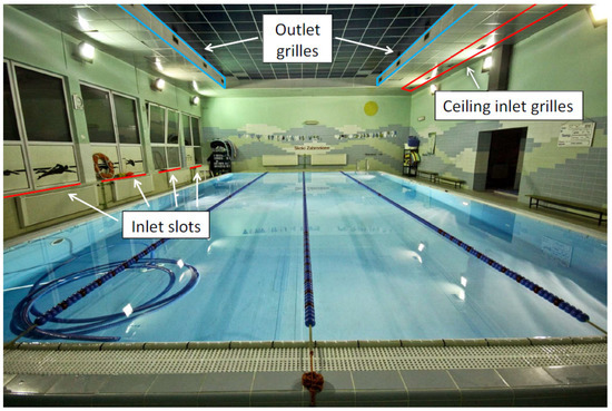
Figure 1.
The view of the interior of the analysed indoor swimming pool.
The swimming pool had two external partitions: the south-western wall with windows and the north-western wall. The north-eastern wall was adjacent to the changing rooms and the south-eastern wall was adjacent to the sports hall. Underneath swimming pool floor was a basement and above the ceiling was an unheated attic. The insulation of the external partitions did not meet the requirements [24], as the heat transfer coefficients of the external walls were: 0.22 W/m2K for the north-western wall and 0.34 W/m2K for the south-western wall.
Indoor heat sources in the swimming hall were: people, lighting and heaters. The internal sources of moisture were: people, water surface and wet floors. The source of moisture in the facility was also the air supplied by the diffusers and by infiltration.
The swimming pool was equipped with mixing ventilation system. The system operated continuously in a constant air volume mode throughout a whole day. The air was supplied by twelve inlet slots along the windows, two slots under each window, and through seven ceiling supply grilles installed on the supply duct located in the suspended ceiling above the floor along the north-eastern wall. The air was exhausted under the ceiling through twelve exhaust grilles placed on the exhaust duct in a recess in the suspended ceiling, six grilles on both sides of the recess. The air was processed in the central ventilation unit, which included: a two-stage heat recovery in the form of a recuperator (heat pipe), heater, mixing chamber, filters and fans.
3.2. Energy Analyses Methodology
Energy calculations for the ventilation system operation of the swimming pool were carried out using the IDA ICE (Indoor Climate and Energy) software [25]. The developed computer model of the swimming pool is shown in Figure 2.
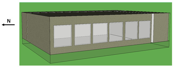
Figure 2.
Model of the analysed swimming pool developed in the IDA ICE software.
Energy analyses were carried out for the whole year, with the use of climate data for Katowice [26]. The analysed swimming pool was located 30 km from Katowice. Outdoor air parameters (air temperature te, relative humidity φe) used for calculations were adopted in accordance with the standard [5] for the 2nd climate zone (te = 30 °C, φe = 45%) in summer and [27] for the 3rd zone climate (te = − 20 °C, φe = 100%) in winter.
In order to calculate the annual energy consumption of the ventilation system, the following data were defined in the software: ventilation air volume flow rate for the winter, transition and summer periods, air parameters in the occupied zone, internal moisture and heat gains, the required supply air temperature as a function of outdoor air temperature tS = f(te), the share of outdoor air in the supply air as a function of outdoor air temperature ne = f(te) and the duration of winter, transition and summer periods, as well as periods of operation of individual devices in the air handling unit. The latter data were determined based on t-te charts, described in the following section. It was also necessary to provide fans’ static pressure and the efficiency of the counter-flow heat exchanger in the two-stage heat recovery system, as well as to declare the CAV system.
The ventilation air volume flow rate was determined according to the formula (1), in which two different values of the specific humidity of the outdoor air in summer were assumed for the analysed calculation variants: xe = 0.012 kg(H2O)/kg(dry air), according to the Polish standard [5] or xe = 0.009 kg(H2O)/kg(dry air), according to the German guidelines [6]. The calculation results are presented in Table 1.

Table 1.
Boundary conditions for the tested variants of the ventilation system operation.
3.3. Analysed Variants
Energy analyses were carried out for three various values of the volume flow rate of air supplied by means of general mixing ventilation (D1, D2 and D3 variants) and the D4 variant, in which additionally to the general ventilation, local air supply to the lifeguards zone was applied.
According to ASHRAE [26], the recommended air change rates in the swimming pool should be in the range from 4 h−1 to 6 h−1, and according to the guideline [28]—in the range from 3 h−1 to 4 h−1. In Poland, in designing the ventilation of swimming pools, the air change rate is usually 8 h−1.
In the D1 variant, the air change rate z = 8 h−1 was assumed. On this basis the air volume flow rate was calculated, while the specific humidity of the supply air was assumed to be equal to the specific humidity of the outdoor air in summer xe = 0.012 kg(H2O)/kg(dry air), according to the standard [5]. Then, the design specific air humidity in the facility was xi = 0.013 kg(H2O)/kg(dry air).
In the D2 variant, the air change rate z = 6.3 h−1 was assumed. It was calculated on the basis of the amount of ventilation air necessary to ensure the limit value of relative humidity xi = 0.016 kg(H2O)/kg(dry air), while the specific air humidity of the outdoor air was assumed xe = 0.012 kg(H2O)/kg(dry air), according to the standard [5].
In the D3 variant, the air change rate z = 3.5 h−1 was assumed. It resulted from the assumption of the specific humidity of the outdoor air xe = 0.009 kg(H2O)/kg(dry air), in accordance with the guidelines [6], and the limit value of specific indoor air humidity xi = 0.016 kg(H2O)/kg(dry air). If it was assumed that the specific humidity of the outdoor air was xe = 0.012 kg(H2O)/kg(dry air), according to the standard [5], then at the declared number of supply air changes z = 3.5 h−1 the design specific indoor air humidity would have reached the value of xi = 0.019 kg(H2O)/kg(dry air) and exceeded the limit one.
In the D4 variant, the supply air volume flow rate for general ventilation was adopted as in the D3 variant, and moreover, an additional local air supply was directed to the lifeguard zone, assuming the air change rate in this zone z = 8 h−1. The total supply air volume flow rate in this variant was the sum of the supply air volume flow rate for general ventilation and local ventilation for the lifeguard zone. It was assumed that at a reduced value of the air volume flow rate for general ventilation, as in the D3 variant, in the case of higher than the limit value of specific indoor air humidity xi, an additional local air supply directed to the lifeguards zone would be activated.
Figure 3 shows the view of the analysed swimming pool with the lifeguard zone marked, which was located in the place of the actual lifeguard stand, by the south-eastern wall. The following dimensions of the lifeguard zone were assumed: length 2.5 m, width 2 m, height 2 m. Therefore, the volume of this zone was 10 m3, which, at the assumed number of air changes in this zone z = 8 h−1, resulted in a supply air volume flow rate 80 m3 for local ventilation. Local air supply to this zone was provided by a supply air grille, with a surface of 0.027 m2, located directly above the centre of the zone and mounted on the supply air duct at a height of 4.4 m above the floor level.
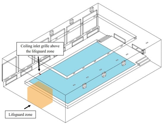
Figure 3.
The view of the analysed swimming pool with the location of the lifeguard zone with local air supply in the D4 variant.
In all analysed variants, apart from the day-time operation of the ventilation system, the night-time operation mode was also considered (non-bathing period). It was assumed that in the night-time mode, in the winter period, the ventilation system worked with 100% recirculated air and it covered only heat losses. In the summer period the unit operated continuously with outdoor air, removing moisture gains.
Energy analyses of each of the four variants D1-D4 were carried out taking into account two methods of heat recovery in the air handling unit and two operating modes of the air handling unit: day-time (bathing period) from 8:00 to 21:00 from Monday to Friday and night-time (non-bathing period) from Monday to Friday from 21:00 to 8:00 and on Saturdays and Sundays throughout the day. In the winter and transition periods in day-time mode, for all analysed variants, the following heat recovery methods in the air handling unit were compared:
- one-stage system with exhaust air recirculation (variants D1.1–D4.1),
- two-stage system with recirculation and counter-flow heat exchanger (variants D1.2–D4.2).
3.4. Determination of Boundary Conditions
To calculate the moisture emission from the pool water surface, the calculation formula (2) was used, in accordance with the guidelines [6]. The selection of this calculation method was made on the basis of previous research [29], in which six different methods of calculating moisture emission from the pool water surface were analysed. Moisture emission from the pool water surface was calculated according to the formula [6]:
In the day-time operating mode of the swimming pool, normal activity of swimmers was assumed, therefore the moisture evaporation coefficient was B = 20 g/(m2∙h∙hPa), while in the night-time mode the operation of the air handling unit with full air recirculation and a calm water surface were assumed. The moisture evaporation coefficient was then B = 5 g/(m2∙h∙hPa), which reduced the emission of moisture. The indoor temperature was lowered to ti = 29 °C at night. The specific indoor air humidity was assumed in accordance with the sultriness curve for the swimming pools xi = 0.016 kg(H2O)/kg(dry air). The supply air volume flow rate was determined so as not to exceed the supply air temperature tN = 45 °C, in accordance with the regulation [30].
A detailed analysis of air treatment processes for all variants of the day-time mode was carried out using the h-x and t-te charts. In winter, based on the h-x charts, the maximum supply air temperature was obtained and it was verified whether there was a need for a preliminary heater in the air handling unit. The parameters of indoor air were set to ensure that the limit value of specific air humidity xi = 0.016 kg(H2O)/kg(dry air) was maintained in the occupied zone. The indoor air temperature in winter period was 31 °C. In summer, in all variants in the day-time operation mode it was assumed that the outdoor air was supplied without changing its parameters. The indoor air temperature was therefore dependent on the outdoor air temperature.
In the variants with one-stage heat recovery, in the day-time mode of the winter period, the outdoor air was first mixed with the recirculating air in the mixing chamber in a ratio that ensured the maintenance of the required indoor air relative humidity and then the mixed air was heated in the heater to the appropriate supply air temperature. In the D3.1 and D4.1 variants, it was necessary to use an additional preheater before the mixing chamber to make sure that the air condition after mixing was not in the fog area and undesirable dehumidification of the air, due to the condensation of moisture, did not occur. Taking into account the required indoor air humidity, the operating periods of the preliminary heater were set so that the mixing point was above the relative humidity line φ = 100%. In the D3.1 and D4.1 variants, the air was preheated to a temperature of 2 °C.
In the variants with two-stage heat recovery, in the day-time mode of the winter period, first the heat was recovered from the exhaust air in the counter-flow heat exchanger, then the recirculation air was mixed with the outdoor air in the mixing chamber, and finally the air was heated to the required supply air temperature. According to the manufacturer’s data, the efficiency of the counter-flow exchanger was assumed to be 96% in winter.
An exemplary h-x chart showing the ventilation air treatment processes for the D1.2 variant with two-stage heat recovery is shown in Figure 4.
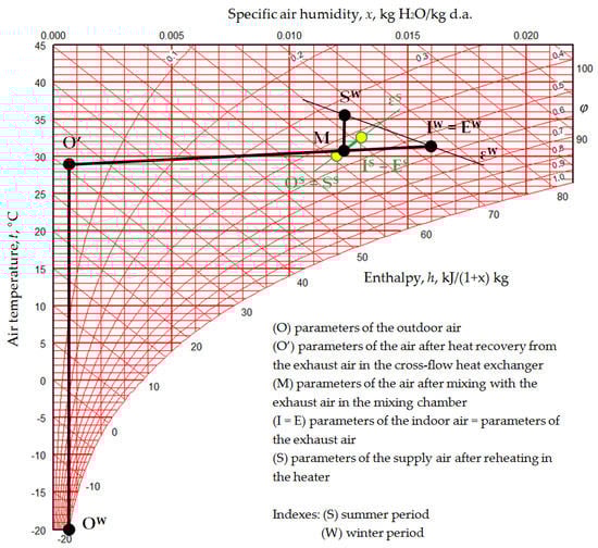
Figure 4.
The h-x chart with the course of the ventilation air treatment process in winter and summer for the D1.2 variant (with two-stage heat recovery); EW-E’—first heat recovery stage, M-SW—second heat recovery stage.
Regardless of the day-time mode, in the night-time mode, the air treatment consisted in heating the recirculation air to the supply air temperature selected so as to maintain the required indoor air temperature.
The t-te chart enables the presentation of the course of air temperature changes in different parts of the ventilation system depending on the outdoor air temperature. On the basis of the t-te charts made for all variants of the day-time mode, the ventilation air treatment processes were analysed depending on the outdoor air temperature in the range from –20 °C to 30 °C and the following values were determined: the supply air temperature tS, assuming that it was linearly dependent on the outdoor temperature te, as well as the percentage share of outdoor air in the supply air ne = f(te), periods of operation of individual devices in the air handling unit and the periods of operation of the air handling unit itself—winter, transitional and summer, which were needed in the calculations using the IDA ICE software. It was also assumed that in the D3.1 variant the preheater operated within the outdoor air temperature range te < − 13 °C, and in the D4.1 variant—in the range of te < − 5 °C. The share of outdoor air in the supply air and the values of the outdoor air volume flow rate for all analysed variants of the day-time mode in the winter and transition period are given in Table 1. In the summer period, the share of outdoor air in supply air was 100%.
An exemplary t-te chart showing the year-round course of the ventilation air treatment process for the D1.2 variant with two-stage heat recovery is shown in Figure 5.
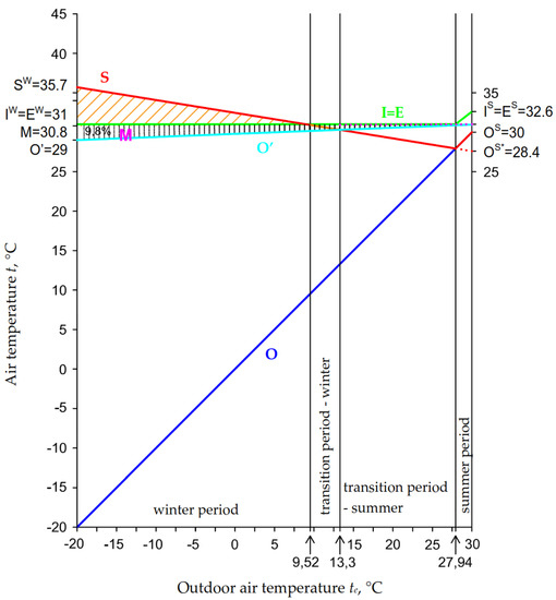
Figure 5.
The t-te chart with the year-round course of the ventilation air treatment processes for the D1.2. variant with two-stage heat recovery (markings as in the Figure 4).
Based on the analysis of air treatment processes, technological charts of ventilation systems and configurations of ThermoCond 38 air handlings units [31] for each analysed variant for the day-time mode were developed and the devices included in the air handling unit were selected. This allowed to determine for each variant the following: the efficiency of the counter-flow heat exchanger, the static pressure of the supply and exhaust fans and the air temperature increase in the fan (0.3 °C in each variant), which served as data for the calculations in the IDA ICE software.
In all variants, the route of ventilation ducts was adopted in accordance with the actual one in the analysed swimming pool, but the dimensions of the ducts and fittings were adjusted to the value of the ventilation air volume flow rate in each variant. In the calculations of pressure losses in the supply and exhaust systems, pressure losses on the supply and exhaust elements equipped with air dampers were taken into account. In the D3.1 and D4.1 variants, the air flow resistance of the electric preheater was also considered.
Table 1 presents the boundary conditions for the energy analysis of the tested variants of the ventilation system in the swimming pool.
Heat and moisture gains were set in the software, as well. The total value of moisture gains emitted from the pool water surface, calculated in accordance with [6], and the wet floor was: for the D1 variants 0.0079 kg/s, for the D2 variants 0.0069 kg/s, for the D3 and D4 variants 0.0066 kg/s. Heat gains from lighting lamps were 1 kW and from heaters in winter about 5 kW. Heat gains from lamps and heaters were assumed on the basis of their power values and the knowledge of how many devices were activated in the facility. It was assumed that the heat gains from people in the water were not large and therefore were not set in the program.
In IDA ICE software for the D1.1 and D2.1 variants with one-stage heat recovery, an air handling unit with a mixing chamber was selected, and for the D3.1 and D4.1 variants, an air handling unit with a mixing chamber and an additional preheater was used. For variants with two-stage heat recovery, a separate configuration of the air handling unit equipped with a mixing chamber and heat exchanger was created from the software components.
Figure 6 shows an example configuration of the air handling unit for the two-stage heat recovery variants in IDA ICE software.
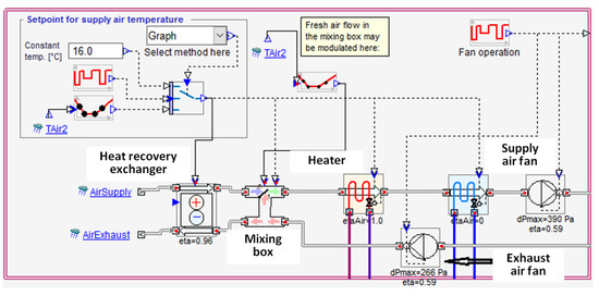
Figure 6.
An example of an air handling unit configuration for variants with two-stage heat recovery in the IDA ICE software.
To introduce variable parameters dependent on the outdoor air temperature into the IDA ICE software for all analysed variants of the ventilation system operation and corresponding air handling unit configurations the setpoint controller was used in the form of a function of outdoor air temperature. This option was used to declare the supply air temperature tS = f(te), the share of outdoor air in the supply air ne = f(te) and the periods of operation of the devices in the air handling unit.
4. Results
Adopting different assumptions for the calculation of ventilation air volume rate in the swimming pool, based on various recommendations, resulted in their different values. Adopting according to [5], with a lower number of air changes than recommended in Poland, resulted in a reduction of the air volume flow rate by over 20% (the D2 variant), and the application of German standards [6] reduced the supply air volume flow rate by over half (the D3 variant), as summarized in Table 1.
In Poland, the regulation on the methodology for determining the energy performance of a building [32], which is based on the standard [33], is used for the energy assessment of buildings. According to this regulation, the energy assessment covers the annual energy demand of the building for heating and ventilation systems, domestic hot water preparation, cooling, built-in lighting installations and for auxiliary devices used in these systems.
As a result of these calculations, three energy indicators are obtained: the annual demand for useful energy, final energy and non-renewable primary energy. They are related to the size of the heated/cooled area and are expressed in kWh/(m2∙year).
On the basis of the simulations the annual final energy and non-renewable primary energy indicators (related to 1 m2 of the facility surface area) were determined. To calculate the non-renewable primary energy indicators in the software, the coefficients of non-renewable primary energy expenditure for the production and delivery of energy or energy for technical systems: for electricity—value 3.0 and for fuel—value 1.1, were assumed in accordance with the regulation [32]. The air was heated by the water heater for which the working medium was prepared in the gas-fired boiler.
Figure 7 presents the values of the indicators of the annual demand for final energy for the analysed variants of the ventilation system operation. In the Figure 8 the indicators of the annual demand for non-renewable primary energy are presented. Both figures specify the energy for heating the ventilation air (for heating the working medium in the water heater) and the electricity needed for its transport (for supplying the fans), and in the D3.1 and D4.1 variants also for powering an electric heater. The results presented for all variants are the sum of the energy consumed during day-time and night-time operation modes of the air handling unit.
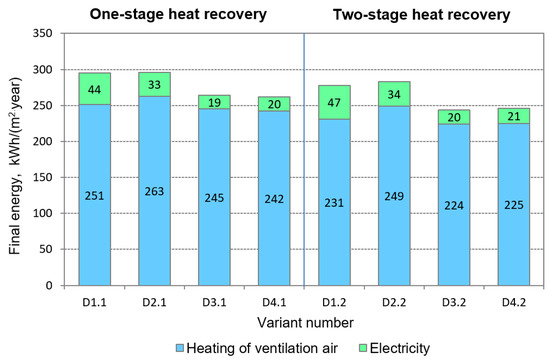
Figure 7.
Indicators of final energy demand for the analysed variants of ventilation system operation.
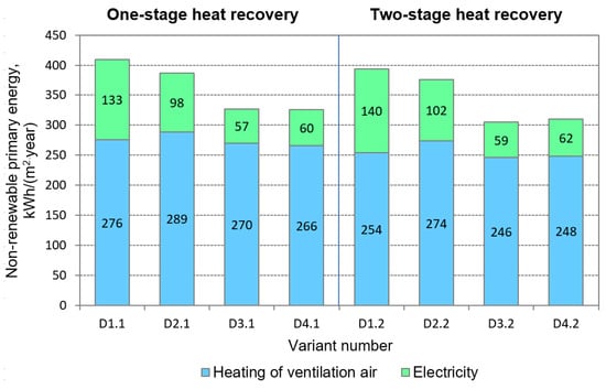
Figure 8.
Indicators of non-renewable primary energy demand for the analysed variants of ventilation system operation.
5. Discussion
The highest final energy demand (Figure 7) was obtained in the D1.1 and D2.1 variants, i.e., in one-stage heat recovery and with the highest ventilation air volume flow rate. The amount of auxiliary electricity demand accounted for 8% to 17% of the total final energy. The highest final energy for heating the ventilation air occurred in the D2.1 variant with one-stage heat recovery. The least energy was required for this purpose for the D3.2 variant with two-stage heat recovery. The difference was 15% of the higher value. For each supply air volume flow rate, the variants with two-stage heat recovery were characterized by a lower demand for final energy for air heating than the variants with one-stage heat recovery. There was lack of correlation between the supply air volume flow rate and the final energy demand. In the D2.1 and D2.2 variants, the demand for energy for heating the ventilation air was higher than in the D1.1 and D1.2 variants, despite a lower value of the total supply air volume flow rate. This was due to the higher share of external air in the supply air in the D2.1 and D2.2 variants compared to the D1.1 and D1.2 variants, respectively. A similar regularity could be noticed when comparing the variants with electric heater D3.1 and D4.1. The figure also shows that the demand for electricity decreased along with the decrease in the air volume flow rate. Final energy consumption was higher in the case of air handling unit with two-stage heat recovery, which resulted from additional pressure losses due to the air flow through the counter-flow heat exchanger.
Conclusions regarding the results of calculations of indicators of non-renewable primary energy demand for each variant (Figure 8) are similar to those for the indicators of final energy demand. In order to lower these values, the use of renewable energy sources such as heat pumps and photovoltaic installations should be considered.
Figure 9 presents how the reduction of the ventilation air volume flow rate in the D2, D3 and D4 variants for one- and two-stage heat recovery influenced the change in the annual final energy demand for the ventilation of the swimming pool in comparison to the variant D1, with the highest value of the ventilation air volume flow rate.
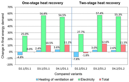
Figure 9.
Change in the final energy demand after reducing the ventilation air volume flow rate in the D2, D3 and D4 variants in comparison to the D1 variant.
In the D2 variant (z = 6.3 h−1) in comparison to the D1 variant (z = 8 h−1), the final energy demand didn’t increase for one-stage heat recovery and increased by 1.8% for two-stage heat recovery. This was due to the higher share of outdoor air in the supply air in this variant, which resulted in an increase in the demand for ventilation air heating by 4.8% for one-stage heat recovery and by 7.8% for two-stage heat recovery.
In the D3 variant (z = 3.5 h−1) in comparison to the D1 variant (z = 8 h−1), the final energy demand was reduced by 10.5% for one-stage heat recovery and by 12.6% for two-stage heat recovery. This was mainly due to the reduction of electricity consumption by 56.8%, as the final energy consumption for ventilation air heating decreased only a little, i.e., by 2.4% ÷ 3.0%.
In the D4 variant (z = 3.5 h−1 with additional air supply to the lifeguards zone), really small difference in final energy demand was obtained—only about 1% in comparison to the variant D3, which means that supplying an additional ventilation air volume flow rate to the lifeguard zone had no significant impact on the energy demand of the swimming pool.
Figure 10 presents the effect of the application of two-stage heat recovery on the annual reduction in final energy. The highest energy savings occurred in the D3 variant and amounted to 8%, while the lowest occurred in the D2 variant and amounted to 4.1%.
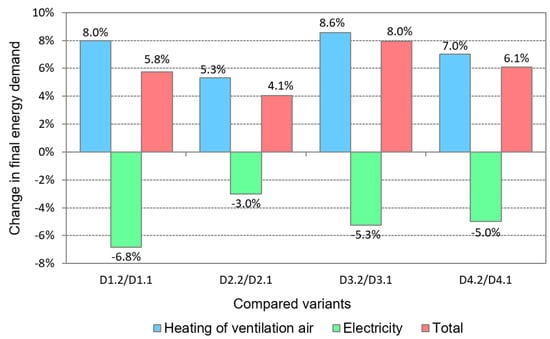
Figure 10.
Change in the final energy demand after applying two-stage heat recovery in comparison to one-stage heat recovery.
Due to the use of the heat exchanger, energy savings for ventilation air heating were obtained from 5.3% in the D2 variant to 8.6% in the D3 variant, but at the same time there was an increase in electricity consumption from 3% in the D2 variant to 6.8% in the D1 variant, which was caused by an increase in pressure losses due to the air flow through the heat exchanger and thus an increase in energy consumption to drive the fans.
Currently, in designing the ventilation of swimming pools, the goal is to make the ventilation systems as energy-efficient as possible. The reduction of energy demand is often achieved by reducing the ventilation air volume flow rate, while accepting that it will result in deterioration of thermal comfort conditions in the swimming pool. The worst period of the year due to increased air humidity is summer. For the analysed variants, in this period, the air humidity content xi was 0.013 (the D1 variant), 0.016 (the D2 and D3 variants) and 0.019 kg(H2O)/kg(dry air) (the D4 variant). The value for the D4 variant was for general ventilation, as exceeding the limit value would not be experienced by people submerged in water. At the same time, a favorable value of the local air volume flow rate for swimming pools was supplied to the lifeguards zone. This should ensure better air mixing and, as a result, an improvement in thermal-moisture conditions in this zone. To ensure adequately low air humidity in the whole swimming pool, air dehumidifying could be applied. The use of it would increase the energy consumption.
The paper focused mainly on the aspects related to energy consumption of the swimming pool ventilation process. The basis of the conducted energy analyses is the assumption that the indoor air is perfectly mixed. This assumption is justified because the facility used mixing ventilation with the flow of air from the bottom to the top of the facility, i.e., in the direction of water vapor flow. It is also the most popular air distribution solution in swimming pools. Two variants of this solution are most often used. In the first one, the air is supplied by slot diffusers located in the floor along the windows on both sides of the facility and removed by exhaust elements under the ceiling, centrally over the pool basin —it allows uniform ventilation of the whole swimming pool, so this solution is used even in the case of objects with large cubic capacity. In the second one, the air is supplied along one, mostly glazed wall, while it is exhausted under the ceiling on the opposite side of the hall—the lack of symmetry in the air distribution may deteriorate the quality of ventilation of a part of the facility, so this solution is mainly used in smaller swimming pools, one-side glazed, long but narrow and less high. This variant of air supply was applied in the analysed facility.
A very important issue is, therefore, the correct selection of air distribution solution in the swimming pool, which determines the efficiency of removing moisture and contaminants and obtaining appropriate homogeneous environmental conditions. The paper proposed a solution (the D4 variant) to improve the work comfort of lifeguards by installing an additional local air supply. This solution, apart from the reduced energy consumption, due to the local air supply, should ensure lower air humidity in this place in comparison to the rest of the facility. The effectiveness of such a solution would need to be further investigated.
6. Conclusions
Indoor swimming pools are sports facilities characterized by significant annual energy consumption, mainly for ventilation, heating and pool water preparation. Therefore, an important research problem is to analyse the possibilities of reducing this consumption. Taking into account the number of school swimming pools in Poland, which account for about 23% of the total number of training and recreational swimming pools, one of them was selected for energy analyses of the ventilation system. The evaluation of energy consumption of ventilation processes in this facility included the treatment and transport of ventilation air. It was determined how the reduction of the supply air volume flow rate affected the annual energy consumption for the ventilation of the swimming pool, and also how it could be reduced by using two-stage heat recovery in the air handling unit compared to one-stage heat recovery.
Based on the results of conducted energy simulations for the analysed swimming pool at various values of the ventilation air volume flow rate and various variants of the air handling unit operation, it was found that:
- The reduction of the supply air volume flow rate resulted in reduced energy expenditure on ventilation. The biggest energy saving was obtained in the case of electricity needed for ventilation air transport (for supplying the fans). The difference in final energy demand between the D1 variant with the highest air volume flow rate compared to the D3 variant with the smallest air volume flow rate was about 3% for heating the ventilation air and about 58% for electricity, which was about 12% of the total energy consumption.
- The application of the local air supply to the lifeguards zone (the D4 variant) only slightly influenced the change (by 1%) in final energy demand for the ventilation system. Such a solution requires further investigation due to the expected improvement in air quality in the lifeguards zone with only a slight increase in total energy consumption of ventilation system.
- As a result of using two-stage heat recovery instead of one-stage heat recovery, the highest final energy saving of 8% was obtained for the D3 variant with the smallest air volume flow rate. A smaller effect of the application of two-stage heat recovery was obtained in the D2 variant, in which the final energy saving was 4.1%.
Further research in the field of energy analyses for swimming pools should concern the impact of the application of renewable energy sources and methods of automatic regulation of the ventilation system on the total energy consumption. For this reason, it is planned to analyse the impact of the heat pump application, instead of a counter-flow heat exchanger, in a two-stage heat recovery system on energy demand in the ventilation process. However, in this case, it will be necessary to examine the impact of the heat pump evaporator defrosting on the energy consumption.
Author Contributions
Conceptualization, P.C.; methodology, P.C.; investigation, formal analysis, P.C., J.K.; resources, J.K.; writing—original draft preparation, review and editing, P.C., J.K. All authors have read and agreed to the published version of the manuscript.
Funding
This research received no external funding.
Institutional Review Board Statement
Not applicable.
Informed Consent Statement
Not applicable.
Data Availability Statement
The data presented in this study are available on request from the corresponding author.
Acknowledgments
The work was supported by the Polish Ministry of Science and Higher Education within research subsidy.
Conflicts of Interest
The authors declare no conflict of interest.
Nomenclature
| supply air volume flow rate (m3/h) | total mass flux of emitted moisture (kg/h) | ||
| pi | partial pressure of water vapor at room air dew point (kPa) | mass flux of emitted moisture from pool water surface (kg/h) | |
| pw | partial pressure of water vapour at the saturation state and the temperature of water surface (kPa) | F | pool water surface (m2) |
| xs | specific air humidity of supply air (kg H2O/kg dry air) | ||
| ti | indoor air temperature (°C) | xi | specific air humidity at room air dew point (kg H2O/kg dry air) |
| te | outdoor air temperature (°C) | ||
| ts | supply air temperature (°C) | xe | specific air humidity of outdoor air (kg H2O/kg dry air) |
| ρs | air density of supply air (kg/m3) | ||
| φe | outdoor air relative humidity (%) | ne | share of outdoor air in supply air (%) |
| z | air changes per hour (h−1) | B | evaporation coefficient (g/(m2hhPa)) |
References
- Trianti-Stourna, E.; Spyropoulou, K.; Theofylaktos, C.; Droutsa, K.; Balaras, C.; Santamouris, M.; Asimakopoulos, D.; Lazaropoulou, G.; Papanikolaou, N. Energy conservation strategies for sports centers: Part B. Swimming pools. Energy Build. 1998, 27, 123–135. [Google Scholar] [CrossRef]
- Ribeiro, E.M.; Jorge, H.M.; Quintela, D.A. An approach to optimised control of HVAC systems in indoor swimming pools. Int. J. Sustain. Energy 2014, 35, 1–18. [Google Scholar] [CrossRef]
- Calise, F.; Figaj, R.D.; Vanoli, L. Energy and Economic Analysis of Energy Savings Measures in a Swimming Pool Centre by Means of Dynamic Simulations. Energies 2018, 11, 2182. [Google Scholar] [CrossRef]
- Salonen, H.; Salthammer, T.; Morawska, L. Human exposure to air contaminants in sports environments. Indoor Air 2020, 30, 1109–1129. [Google Scholar] [CrossRef] [PubMed]
- Polish Standard. PN-76/B-83420 Ventilation and Air Conditioning. Calculation Parameters of the Outside Air; Polish Committee for Standardization PKN: Warszawa, Poland, 1976. (In Polish) [Google Scholar]
- VDI Standard. VDI 2089 Part 1: Building Services in Swimming Baths—Indoor Pools; VDI Verein Deutscher Ingenieure e.V: Düsseldorf, Germany, 2010. [Google Scholar]
- Trzeciakiewicz, Z. The experiences of indoor swimming pool exploitation from the point of view of interior environment. Instal 2013, 7–8, 43–47. (In Polish) [Google Scholar]
- Specjał, A.; Lipczyńska, A.; Hurnik, M.; Król, M.; Palmowska, A.; Popiołek, Z. Case Study of Thermal Diagnostics of Single-Family House in Temperate Climate. Energies 2019, 12, 4549. [Google Scholar] [CrossRef]
- Grygierek, K.; Ferdyn-Grygierek, J.; Gumińska, A.; Baran, Ł.; Barwa, M.; Czerw, K.; Gowik, P.; Makselan, K.; Potyka, K.; Psikuta, A. Energy and Environmental Analysis of Single-Family Houses Located in Poland. Energies 2020, 13, 2740. [Google Scholar] [CrossRef]
- Grygierek, K.; Ferdyn-Grygierek, J. Multi-Objective Optimization of the Envelope of Building with Natural Ventilation. Energies 2018, 11, 1383. [Google Scholar] [CrossRef]
- Ferdyn-Grygierek, J.; Bartosz, D.; Specjał, A.; Grygierek, K. Analysis of Accuracy Determination of the Seasonal Heat Demand in Buildings Based on Short Measurement Periods. Energies 2018, 11, 2734. [Google Scholar] [CrossRef]
- Abdo-Allah, A.; Iqbal, M.T.; Pope, K. Energy Consumption Analysis of a Large Building at Memorial University. J. Energy 2019, 2019, 1–21. [Google Scholar] [CrossRef]
- Ding, Z.; Zhu, H.; Wang, Y.; Ge, X. Study and analysis of office building energy consumption performance in severe cold and cold region, China. Adv. Mech. Eng. 2017, 9, 1–21. [Google Scholar] [CrossRef]
- Müller, J.; Kosiba, K. Swimming pool ventilation—is it worth using air handling units without a heat pump? Rynek Instal. 2013, 9, 56–63. (In Polish) [Google Scholar]
- Johansson, L.; Westerlund, L. Energy savings in indoor swimming-pools: Comparison between different heat-recovery systems. Appl. Energy 2001, 70, 281–303. [Google Scholar] [CrossRef]
- Kolaszewski, A.; Więcek, K.; Borowiecki, M. Energooszczędność hal basenowych. Instal 2011, 4, 8–12. (In Polish) [Google Scholar]
- Sun, P.; Wu, J.Y.; Wang, R.Z.; Xu, Y.X. Analysis of indoor environmental conditions and heat pump energy supply systems in indoor swimming pools. Energy Build. 2011, 43, 1071–1080. [Google Scholar] [CrossRef]
- Lazzarin, R.M.; Longo, G.A. Comparison of heat recovery systems in public indoor swimming pools. Appl. Therm. Eng. 1996, 16, 561–570. [Google Scholar] [CrossRef]
- Więcek, K. The costs of ventilation and heating of swimming pool halls with the use of central units of various designs. Rynek Instal. 2014, 3, 33–47. (In Polish) [Google Scholar]
- Zuccari, F.; Santiangeli, A.; Orecchini, F. Energy analysis of swimming pools for sports activities: Cost effective solutions for efficiency improvement. In Proceedings of the Ati 2017—72nd Conference of the Italian Thermal Machines Engineering Association, Lecce, Italy, 6–8 September 2017; Volume 126, pp. 123–130. [Google Scholar]
- Ratajczak, K.; Szczechowiak, E. Energy consumption decreasing strategy for indoor swimming pools—Decentralized Ventilation system with a heat pump. Energy Build. 2020, 206, 109574. [Google Scholar] [CrossRef]
- Marín, J.P.D.; Garcia-Cascales, J.R. Dynamic simulation model and empirical validation for estimating thermal energy demand in indoor swimming pools. Energy Effic. 2020, 13, 955–970. [Google Scholar] [CrossRef]
- Indoor Swimming Pools in Poland—Inventory of Sport Facilities Report (Pływalnie Kryte w Polsce—Inwentaryzacja Bazy Sportowe—in Polish) Ministry of Sport and Tourism. Department of Sports Infrastructure. Warsaw. April 2015. Available online: https://www.gov.pl/web/sport/infrastruktura1 (accessed on 15 January 2021).
- Regulation of the Minister of Infrastructure on Technical Conditions to be Met by Buildings and Their Location (Journal of Laws, Dz.U. poz. 1065) (in Polish). Available online: https://isap.sejm.gov.pl/isap.nsf/DocDetails.xsp?id=WDU20190001065 (accessed on 14 January 2021).
- IDA Indoor Climate and Energy (IDA ICE). Available online: https://www.equa.se/en/ida-ice (accessed on 15 January 2021).
- American Society of Heating, Refrigerating and Air Conditioning Engineers. ASHRAE Handbook; Fundamentals, S.I., Ed.; American Society of Heating, Refrigerating and Air Conditioning Engineers: Atlanta, GA, USA, 2011. [Google Scholar]
- EU Standard. EN 12831-1:2017 Energy Performance of Buildings—Method for Calculation of the Design Heat Load—Part 1: Space Heating Load; European Committee for Standardization: Brussels, Belgium, 2017. [Google Scholar]
- Recknagel, H.; Sprenger, E.; Schramek, E.R. Knowledge Compendium. Heating, Air Conditioning, Hot Water, Refrigeration; Omni-Scala: Wrocław, Poland, 2008; ISBN 978-83-92683-36-0. (In Polish, translation from German Tashenbuch für Heizung+Klima Technik). [Google Scholar]
- Ciuman, P.; Lipska, B. Experimental validation of the numerical model of air, heat and moisture flow in an indoor swimming pool. Build. Environ. 2018, 145, 1–13. [Google Scholar] [CrossRef]
- Regulation of the Minister of Labor and Social Policy of 4 August 2011 Amending the Regulation on General Health and Safety at work (Journal of Laws, Dz.U. nr 173 poz. 1034) (in Polish). Available online: http://isap.sejm.gov.pl/isap.nsf/DocDetails.xsp?id=WDU20111731034 (accessed on 14 January 2021).
- Products: Air Handling Units. Available online: http://www.menerga.pl (accessed on 15 January 2021).
- Regulation of the Minister of Infrastructure and Development of February 27, 2015 on the Methodology for Determining the Energy Performance of a Building or Part of a Building and Performance Certificates (Journal of Laws, Dz.U. poz. 376 with Amendments) (in Polish). Available online: http://isap.sejm.gov.pl/isap.nsf/DocDetails.xsp?id=WDU20150000376 (accessed on 14 January 2021).
- EU Standard. EN ISO 13790:2008 Energy Performance of Buildings—Calculation of Energy Use for Space Heating and Cooling; European Committee for Standardization: Brussels, Belgium, 2002. [Google Scholar]
Publisher’s Note: MDPI stays neutral with regard to jurisdictional claims in published maps and institutional affiliations. |
© 2021 by the authors. Licensee MDPI, Basel, Switzerland. This article is an open access article distributed under the terms and conditions of the Creative Commons Attribution (CC BY) license (http://creativecommons.org/licenses/by/4.0/).