1. Motivation
Wind energy is taking an increasing share in the energy supply of the future, while costs for wind turbines (WTs) steadily decline due to technology improvements. The operational costs of WTs can be reduced by increasing its reliability [
1]. Reliability improvements can be achieved by explicitly considering special load scenarios that are currently not considered sufficiently in the WT development. Dependent on the WT concept, grid faults can lead to dynamic electromagnetic torque excitations with amplitudes significantly higher than the rated torque [
2]. Faults in the power electronics [
3], e.g., the converter, can also induce significant torque excitations [
4,
5].
However, gearbox damages are the main contributor to WT downtime. Gearbox damages occur mainly on bearings and gears of the high speed stage (HSS). Around 48 per cent of the gearbox damages are attributed to the HSS bearings [
6,
7].
Therefore, an investigation of electrical faults and their influence on an increase in the risk of damages to the WT gearbox components is conducted at the CWD in the project DynaGET. As generator torque excitations have the highest influence on the loading of the HSS gearbox components [
5], the HSS bearings are the main focus in this research.
2. Approach
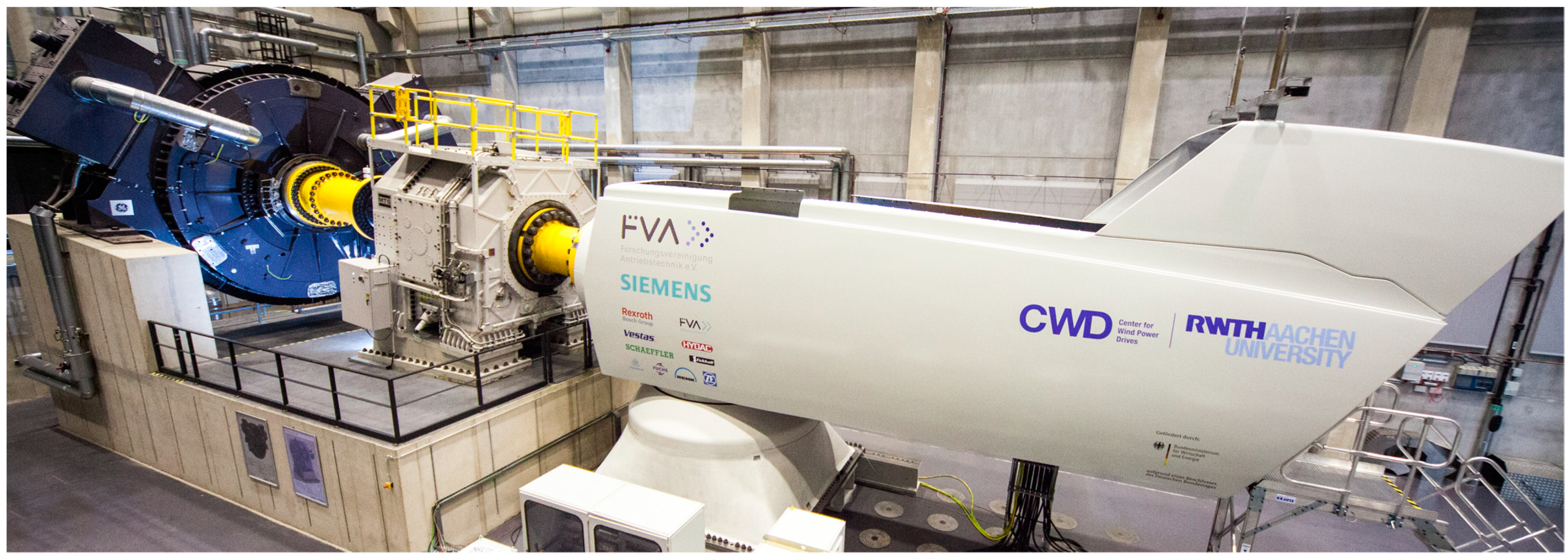
In order to quantify the loads due to grid faults, fault ride through (FRT) experiments can be carried out in the field or on test benches (see
Figure 1). Furthermore, validated multi-body simulation (MBS) models can be used to simulate grid faults and, e.g., short-circuit converter faults that cannot economically be tested on test benches.
For a simulative quantification of the risk of damage to the drive train components during electrical faults, the drive train loads and kinematics have to be calculated and evaluated via damage criteria. For the load calculation, a model of a WT research nacelle, described in
Section 3, is used. Two different grid connection concepts were investigated, while the mechanics of the drive train were not changed. Therefore, the influence of the electrical faults on the mechanical loading can be compared for the different concepts.
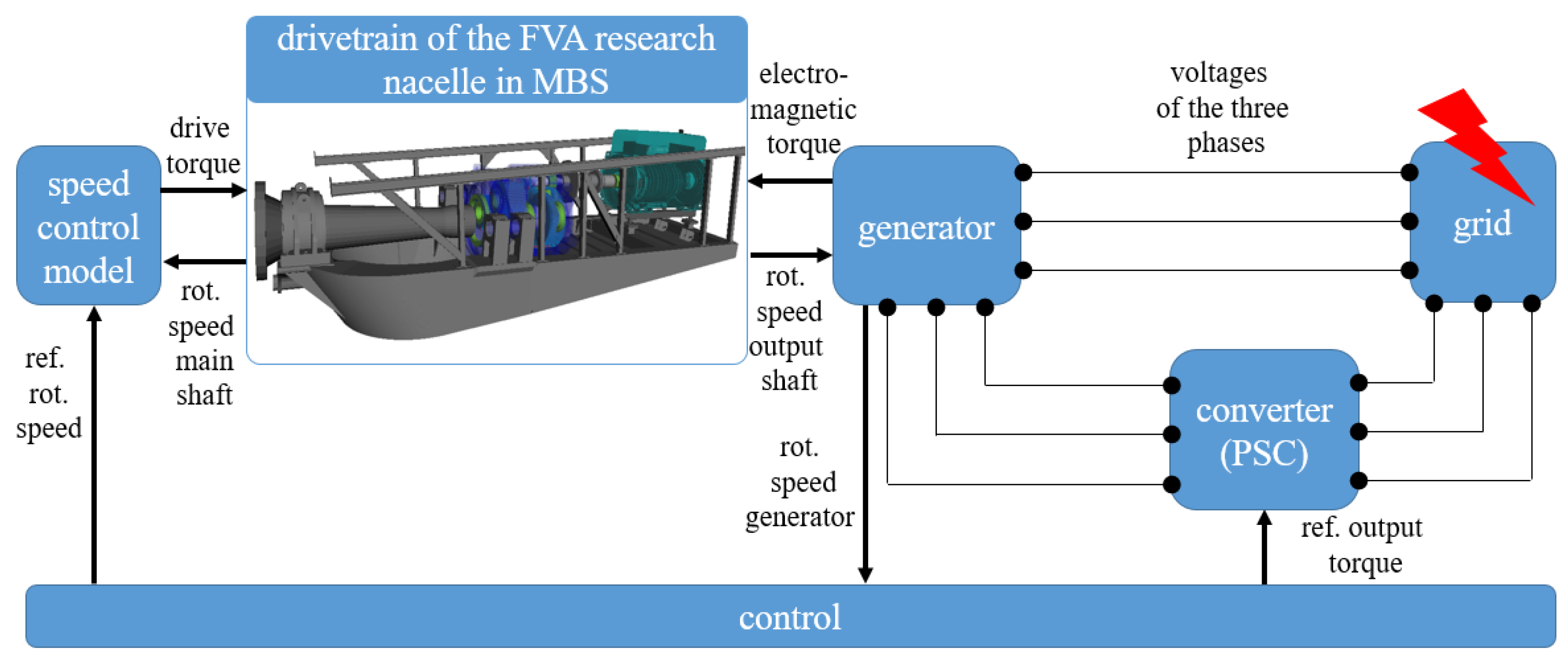
In the doubly fed induction generator (DFIG) concept (see
Figure 2), the WT is only partially decoupled from the grid via the partial scale converter (PSC). Due to the direct connection of the generator´s stator, grid faults affect the electromagnetic field in the stator significantly, which leads to a transient torque excitation [
2]. A fault ride through scenario, corresponding to the current European grid codes, is investigated. The resulting torque and drive train loads are discussed in
Section 4.
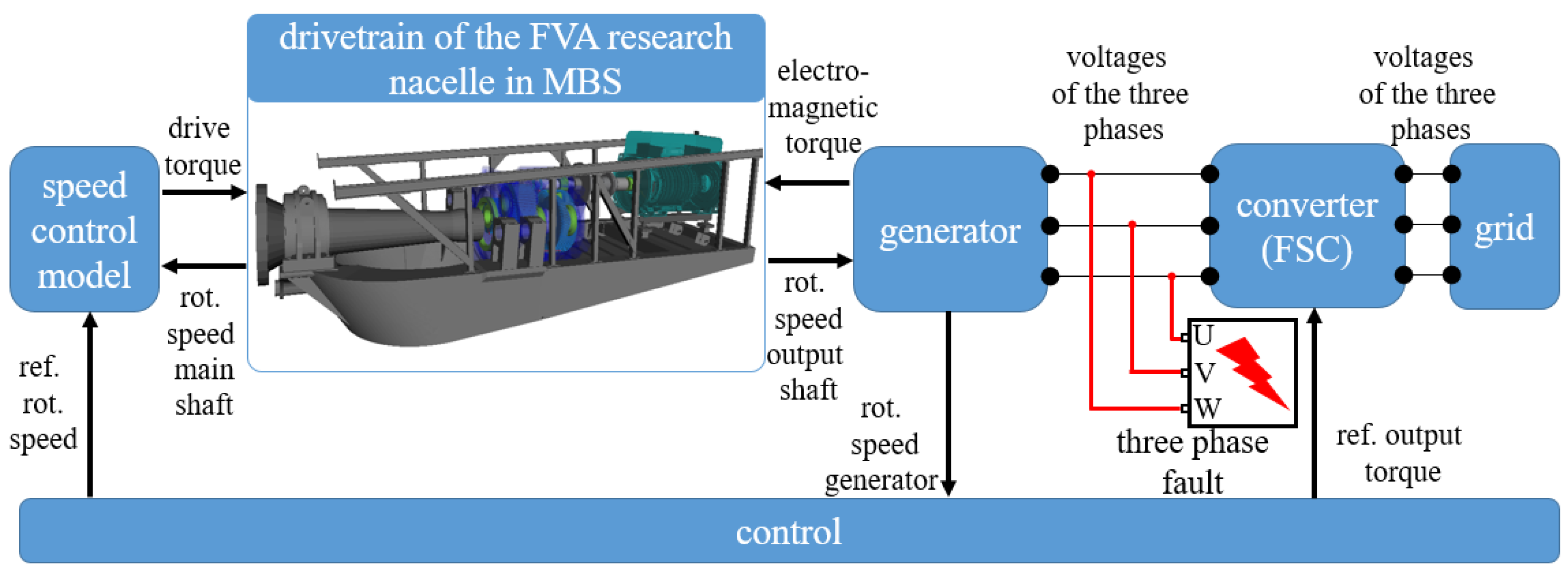
In the full-scale power converter (FSC) concept, the WT is completely decoupled from the grid via the converter and countermeasures, e.g., brake choppers (see
Figure 3). Therefore, in general, grid faults do not induce significant excitations for the FSC concept. Hence, a converter fault is analyzed (see
Figure 3). The fault, its influence on the generator currents, as well as the resulting drive train torque load, is discussed in a previous publication [
8].
In order to quantify the risk of damage to the gearbox bearings a smearing criterion [
9] is evaluated using the MBS results as an input.
3. Models
The drive train model (MBS) is connected with analytical models for the electrical system (see
Figure 2 and
Figure 3) via a co-simulation [
10,
11,
12]. The drive torque of the test bench motor is calculated using a speed control model and implemented as an excitation to the MBS model (see
Figure 2,
Figure 3 and
Figure 4). The faults occur at a HSS rotational speed of 1100 rpm. Besides a rotor weight emulation, the non-torque loads resulting from the wind are disregarded in this paper for an independent evaluation of the loading due to the electrical faults.
For both concepts, the same generator with slight adaptations was used. Specific parameters of the generator (see
Table 1) are provided by the manufacturer. The generator was implemented as an analytical model based on the fundamental electromagnetic waves. This fidelity is sufficient for calculating damage relevant loads within the drive train [
10].
The model of the grid mainly emulates the inductances [
10]. Both the PSC and the FSC are modelled according to the IEC 61400 and other state-of-the-art guidelines [
13].
The drive train model also includes the CWD test bench (
Figure 4) [
10,
11,
12]. This model was chosen for the investigation in this paper because its validity was shown using data from extensive experiments with regard to IEC 61400 and via a converter fault test in idling mode [
4,
5,
10,
11,
12].
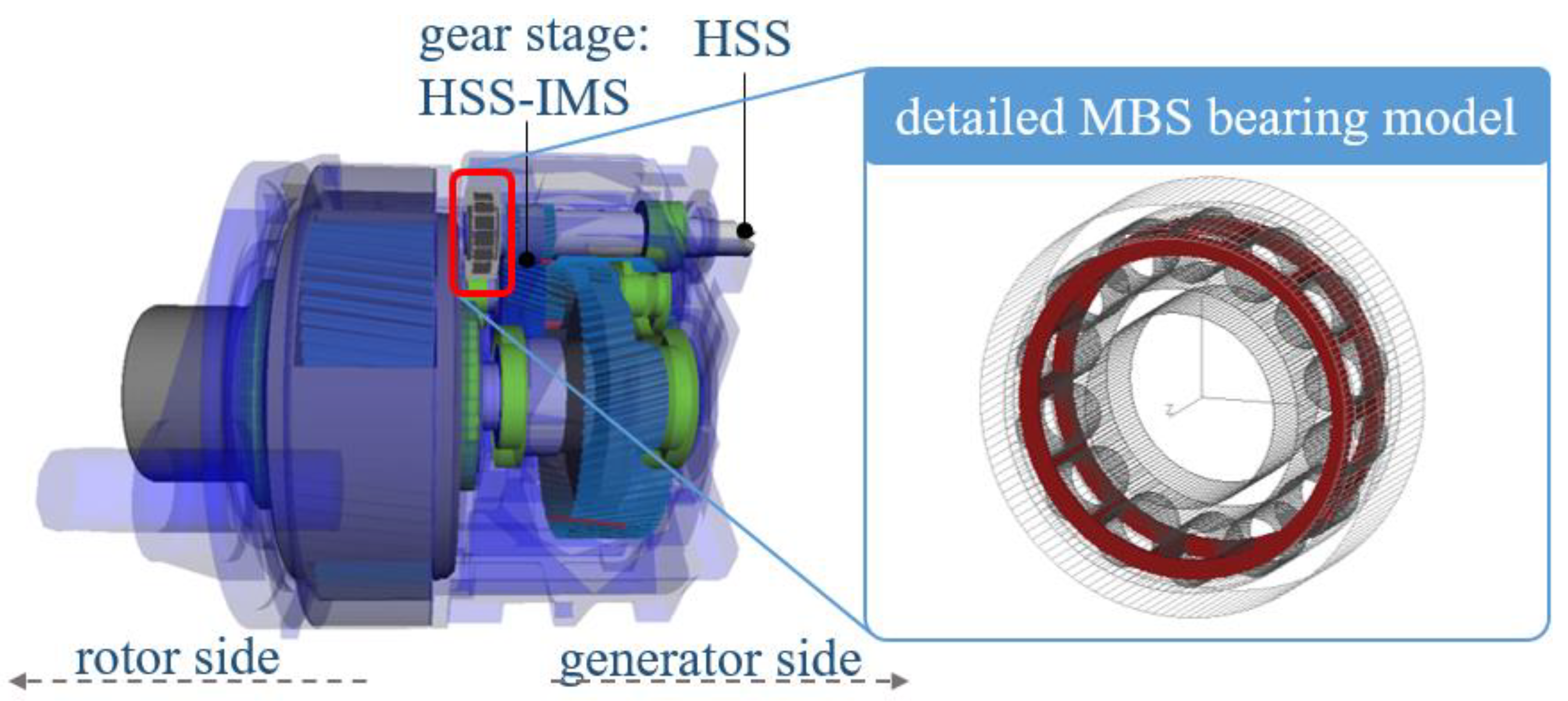
The investigated gearbox (see
Figure 5) has a gear ratio of around 63 and consists of a planetary stage as well as two helical gear stages. The gear wheel contact is implemented via a gear pair force element and backlash is included. The bearings are modelled as spring-damper elements with input functions for the stiffness and damping [
10,
11,
12]. A detailed model is implemented for the rotor side cylindrical roller bearing [
14] (see
Figure 5) in order to calculate the Hertzian contact pressure and the kinematics of each roller for the evaluation of a smearing criterion.
The smearing criterion [
9] derives the power P on Area A and consists of the friction coefficient
μ the difference in circumferential velocity of the contact partners u
1(t) − u
2(t) and the maximum Hertzian contact pressure p
max(t):
4. Results
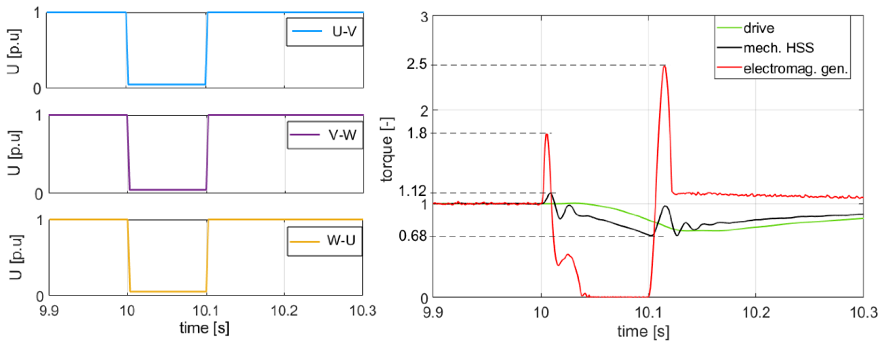
The first load case discussed in this paper’s simulative investigation is the grid fault for the DFIG concept WT (see
Figure 2). The three-phase line-to-line voltages (U
U-V, U
V-W, U
W-U) for the grid fault are shown in
Figure 6 (left). In
Figure 6 (right), the resulting electromagnetic, mechanical HSS and drive torque is shown with regard to the gearbox ratio and normalized by the nominal torque. The grid fault starts at t = 10 s. Over a period of 3 ms, the voltages decreased linearly to 5 per cent of the nominal value. This voltage level was kept for 97 ms. As a result, the generator torque shortly increased to 1.8 times the rated torque before it rapidly decreased to zero. The control detected the fault and the sharp decrease of the generator torque. Therefore, the drive torque, applied via the test bench motor, also started decreasing. The speed of rotation of the HSS increased (see
Figure 7, left) because of the slower decrease in drive torque than in the electromagnetic generator torque, which was a result of the drive´s high inertia. The mechanical HSS torque oscillated shortly after the fault was triggered. It reached 1.12 times nominal value before it decreased to a minimum of around 68 per cent over a period of 97 ms. Then, the fault was cleared and the voltages increased to the nominal value again linearly in 3 ms. As a result, the electromagnetic torque increased rapidly. It shortly reached 2.5 times nominal value before it declined to the rated value again. Therefore, the speed of rotation of the HSS decreased significantly and the mechanical HSS torque increased with a sharp peak. The control also detected the restored normal grid operation and started increasing the drive torque. Subsequently, the mechanical HSS torque steadily increased and reached its nominal value again at t = 11.5 s.
The dynamic torque excitations were transferred to the loading of the drive train components. In
Figure 7 (right), p
max(t) between the rollers and the inner ring of the cylindrical roller bearing is shown exemplarily. After the grid fault occurred, p
max(t) increased initially by a maximum of around 3 per cent for one roller (see
Figure 7, right). Afterwards, the gearbox bracing decreased. Thus, p
max(t) also sank to a minimum of around 80 per cent over a period of 97 ms. As the fault was cleared at t = 10.1 s, p
max(t) peaks for the rollers in contact before it steadily increased due to the increasing drive torque and bracing of the gearbox. At t = 11.5 s, the turbine was at normal operating mode and p
max(t) reached its nominal value again.
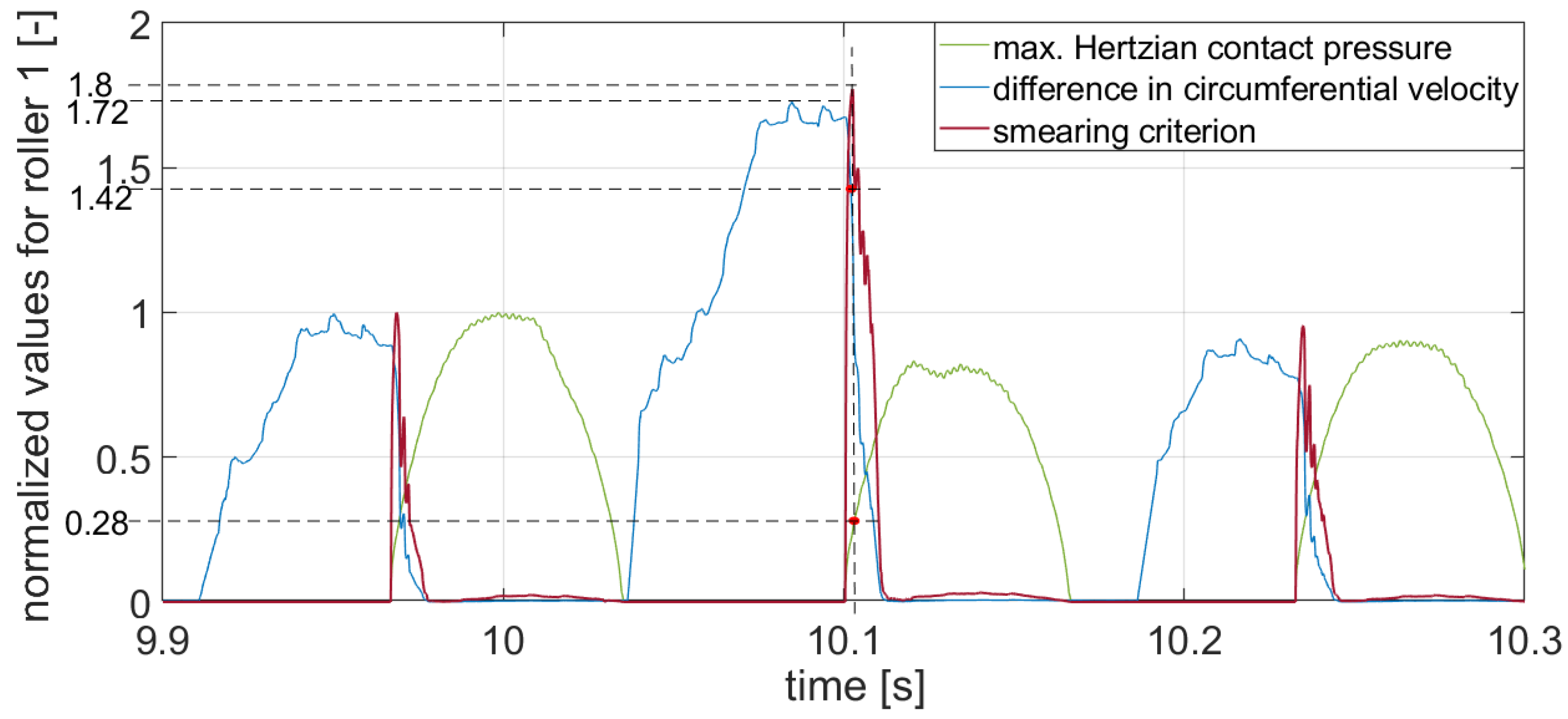
In
Figure 8, the normalized smearing criterion is shown for roller 1, which shows the most critical behavior during the grid fault. The smearing criterion was normalized to its value at nominal torque load. After the fault occurred at second 10, the bracing of the gearbox decreased. Therefore, p
max(t) decreased (see
Figure 7, right). The speed of rotation increased rapidly (see
Figure 7, left). This led to an increase in the maximum difference of circumferential velocity (see
Figure 8, blue line, max. 1.72 times nominal value) due to an increase in slip. As the fault was cleared at t = 10.1 s, the bracing of the gearbox increased rapidly. As the roller entered the load zone again, the slip and, therefore, the difference in circumferential velocity, was still high (1.42 times nominal value), while p
max(t) increased to around 28 per cent of the nominal value. This momentarily led to an increase in the smearing criterion of around 1.8 times in comparison to the nominal value during nominal torque load. After the gearbox was braced again, the speed of rotation stabilized and the maximum difference in circumferential velocity declined to nominal value. Accordingly, the smearing criterion declined to the nominal value again.
The second load case was the converter fault in the WT with FSC concept (see
Figure 3). The resulting highly dynamic torque loading of the WT is discussed in detail in a previous publication [
8]. For reference, the speed of rotation, the drive train torque load and p
max(t) of the rollers of the HSS cylindrical roller bearing is shown in
Figure 9. The dynamic torque excitation led to an oscillation in the HSS speed of rotation. After a short spike, the contact pressure oscillated and decreased rapidly due to the decreasing bracing of the drive train.
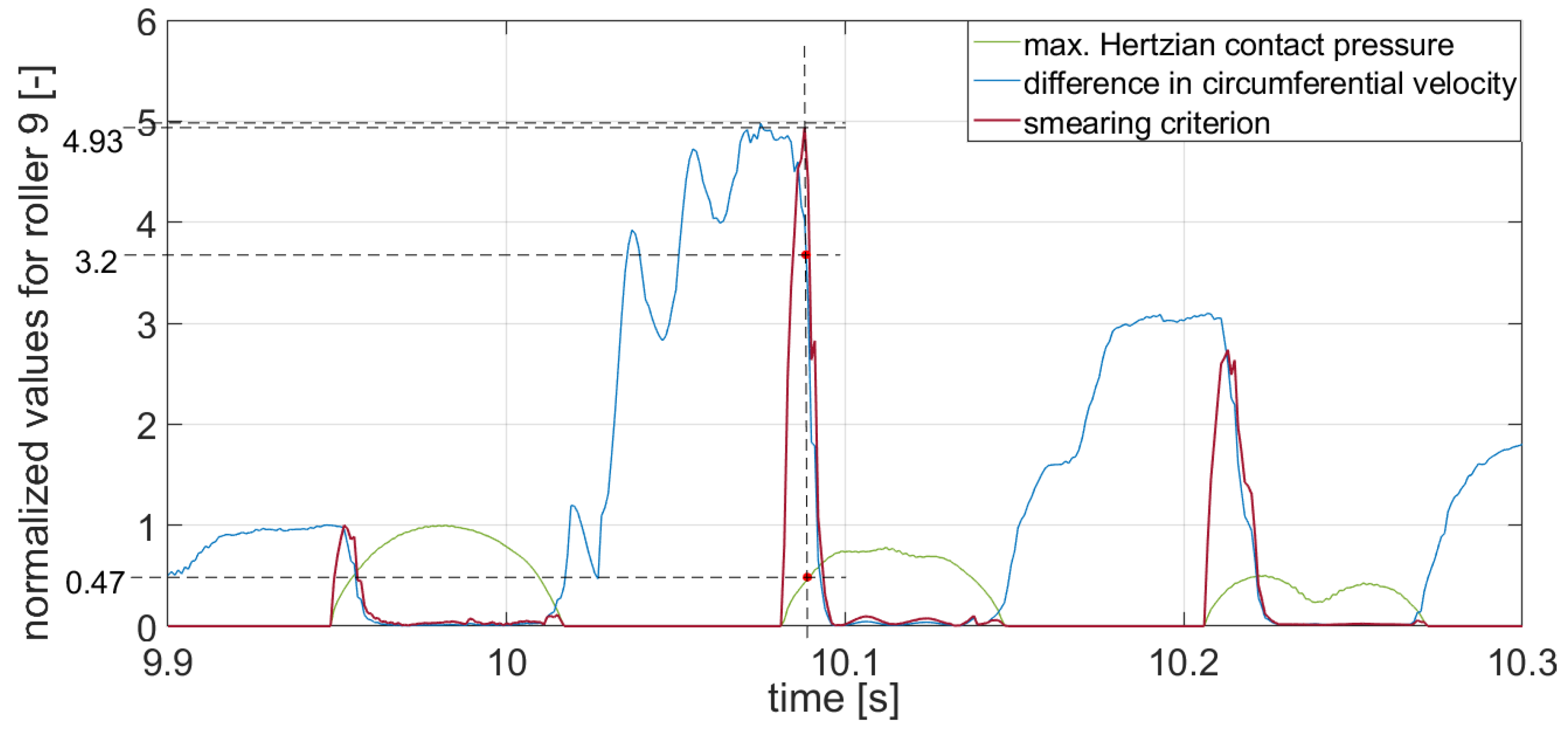
In
Figure 10, the normalized smearing criterion for roller 9, which shows the most critical behavior, is depicted. The smearing criterion was normalized to its value at nominal torque load. As the fault was triggered at second ten, the loading and the speed of rotation started to oscillate significantly (see
Figure 9). As a result of the oscillating speed of rotation, u
1(t) − u
2(t) of roller 9 (see
Figure 10, blue line) increased by a maximum of around 5 times compared to the nominal value. As the roller approached the load zone again, u
1(t) − u
2(t) was still elevated (around 3.2 times nominal value) while p
max(t) already reached around 47 per cent of its nominal value. As a result, the smearing criterion increased by a maximum of 4.93 times compared to the nominal value momentarily. Afterwards, the bracing of the gearbox and, therefore, p
max(t) decreased. Subsequently, the smearing criterion also approached lower levels.


