Article

Integrity Analysis of the Sheath Considering Temperature Effect under Deep and Large-Scale Multi-Section Hydraulic Fracturing

1
State Key Laboratory of Geomechanics and Geotechnical Engineering, Institute of Rock and Soil Mechanics, Chinese Academy of Sciences, Wuhan 430071, China
2
University of Chinese Academy of Sciences, Beijing 100049, China
*
Author to whom correspondence should be addressed.
Energies 2021, 14(21), 7162; https://doi.org/10.3390/en14217162
Submission received: 21 September 2021 / Revised: 14 October 2021 / Accepted: 29 October 2021 / Published: 1 November 2021
(This article belongs to the Topic Enhanced Oil Recovery Technologies)

Abstract

:
Different operations make the borehole temperature change and cause periodic stresses, which often cause variations in the stress state of the sheath or damage. In this paper, the effect of temperature on sheath integrity is investigated. First, the mechanical model of sheath is established and analyzed by shakedown theory. Then, compression experiments of well cement at different temperatures are carried out, and the law of mechanical properties with temperature is obtained. Finally, combining the theoretical analysis and mechanical experiments, the results show that (1) when only the temperature inside the sheath cyclically varies, the negative influence of temperature caused by the practical operations can be negligible. (2) When the internal pressure and temperature act together, the effect of temperature on the sheath is reflected in temperature stress and the change of the cement properties. (3) With the increase of temperature difference (∆T), the cohesion of cement decreases while the internal friction angle increases, and the plasticity characteristics of the cement are enhanced, and the negative effect on the Pmax ascends slowly. (4) The temperature stress is in a positive relationship with the ∆T, and its weakening on the Pmax is about 6% to 7%. (5) Combining the temperature stress and the change of the cement properties, total negative effect of temperature on the sheath accounts for 10% to 12%, when ∆T ranges from 60 to 110 °C.

1. Introduction

For ensuring the long-term and safe production of gas well, the integrity of sheath has obtained more emphasis in recent years. Field experiences and laboratory experiments have both demonstrated that the sheath is likely to fail after downhole operations [1,2,3]. The cement sheath fails mainly because of the loads from variations of wellbore temperature and pressure [4].
In recent years, with the recognition of the important influence of temperature on the sealing failure of sheath, many scholars around the world have carried out a series of research on the mechanical properties of cement at high temperature, the characteristics of cement solidification, the cement slurry formula system and the failure mechanism of sheath seal. Wang Lei and Zeng Yijin [5] carried out triaxial compression and cyclic loading tests under multi-temperature conditions. The results show that the cement paste exhibits elastic brittleness at room temperature, the strength of the cement decreases obviously when the temperature rises to 130 °C, and the elastic modulus also decreases at the same time; the deformation of cement paste at high temperature is mainly axial compression deformation, which has the characteristics of ideal plasticity. Lian [6] carried out the cyclic loading experiments and scanning electron microscopy to focus on microannulus and microcracks in the sheath. Liu Yang and Ai Zhengqing et al. [7] proposed a new two-dimension simulator according to the underground heat transfer construction process. The results show: circulating drilling fluid several times and increasing the pump rate will reduce circulating temperature, and the circulating maximal temperature in winter is lower than in summer, especially for a shallow well. Thus, suitably reducing the design temperature in winter could not affect the pump safety; the temperature coefficient in deep wells is higher than in shallow wells, and the circulating temperature is lower if the borehole size is bigger. Kuanhai [8] set the mechanical model considering the casing and cement sheath as well as formation under non-uniform in situ stress. The influence of many factors on the integrity of cement sheath has been systematically studied. Zhao hu, Wen Daquan [9] et al., investigated temperature distribution on the wellbore in the cementing process and developed a two-dimensional approach of transient heat transfer based on the first law of thermodynamic to predict the wellbore temperature distribution. It is indicated that the hottest temperature is at a point some distance higher than the casing shoe, and the wellbore temperature distribution will be significantly different for different well structures. Water depth, flow rate of booster and density of cementing slurry will also affect the temperature distribution of the wellbore to some degree. Kruszewski [10] created a new method to evaluate integrity by utilizing the wire-line acoustic measurements. It can help to optimize the drilling operation and production. Wang Chunquan and Liu Shibin [11] discussed the influence of different types of wells and annular clearance on cementing circulating temperature. The results show that the temperature coefficient increases with the increase of well depth and decrease of annular clearance in horizontal or high-angle wells. Yu Yongjin and Ding Zhiwei et al. [12] have developed a high temperature filter loss reducer DRF-1 S, a high temperature retarder DRH-2 L and other high temperature cement additives. The cement slurry system is excellent enough to meet the cementing requirements of wellhole circulating temperature 210 °C and the static temperature 230 °C, except for not declining at 230–250 °C. Ye Zhonglang, Zhu Zehua [13] conducted research on the effects of curing temperature, curing pressure and pH value of the slurry water on the curing process of cement slurry. The results show that, in the curing temperature range lower than 110 °C, the compressive strength of cement increases with the rising of temperature, but at higher than 110 °C, it decreases with the increase of temperature. In the curing pressure range of 2 to 8 MPa, the compressive strength increases with the increase of curing pressure; under the same conditions, the compressive strength cured by the cement slurry prepared with acidic slurry water is the highest. LI Haiqing, Yao Yan [14] studied thermal expansion properties of hydraulic cement paste. The results show that thermal expansion curve increases at the initial stage and then decreases, with the temperature increasing in both heat systems, but the temperature of the former heat system at which the thermal expansion ratio reaches a maximum is 70 °C lower than that of the latter. Deng [15] conducted a mechanical model considering the repairing force of the deformation casing with cement sheath according to the inversion method. The results showed that there are three types of damage called micro-annulus, transverse fracture, and longitudinal fracture, which is caused by high contact pressure and pressure fluctuation during repairing. Megan L [16] studied the effect of curing on the mechanical properties of concrete under the condition of effective stress and temperature by using a temperature-controlled hydration cell. Gao Baokui [17] performed an ideal casing–cement–formation system to investigate its integrity under periodic temperature change, which indicates that when the temperature declines, the casing–cement sheath interface will separate because of the radial residual stress. Abdullah S. [18] carried out a finite element modeling to analyze the stress exerted on the casing during the whole life of the well in order to evaluate the influence of pressure and temperature cycles on the long-term integrity of the well. Fred Sabins [19] developed an improved ultra-lightweight cement using ultra-lightweight hollow glass spheres (ULHS) and tested ULHS systems along with other lightweight cement systems, including foamed and sodium silicate slurries to obtain several properties: tensile strength, Young ’ s modulus, and shear bond. Chengwen Wang, Xin Chen [20], by experiments, clarified the influence of nano-SiO2 sol on the strength of Class-G oil well cement considering the microstructure of the cement more compact through impaction and filling into the pore among cement hydration products, which helps to prevent cement from strength retrogression under high temperatures. Wu et al. [21] focused on the effect of heat flow direction and temperature difference on the sheath integrity by an accurate 2D model. They concluded that the heat is from the formation to the casing, which is worse to cement integrity than the opposite direction. Deng Kuanhai [22] carried out the collapsing test for a cemented casing under non-uniform load (NFL). The plastic limit load of a sheath–casing system have been obtained. Zheng Youzhi [23] performed simulations and experiments to compare the many properties of the cement. It is shown by the stress–strain curve that the lower loading rate of set cement is not smooth, but distorted. Moonseo PARK [24] investigated the strength decline of cement caused by temperature cycling. The results show that the unconfined compressive strength declines with the growth of compression ratio ranging from 5 to 50 °C. Hager I [25] performed the impact of high temperature on cement. The results indicate that the effect of a high temperature on concrete involves cement paste and aggregates, as well as the interaction of these two constituents. Patel [26] studied the effect of pressure, mechanical properties, and sheath size on the integrity of sheath. Results indicate that flexible and expanding cement tend to be reliable for the structure versus brittle and non-expanding cement. Andrade [27] created an extensive finite element to assess the law of a casing–cement–formation system, geometric information, and characteristic well-loading events, which will contribute to clarifying the failure mechanisms.

2. Basic Mechanical Model and Hypothesis

The dimensions of sheath are generally fixed with an inner diameter of 139.7 mm and an outer diameter of 233.5 mm, which can be regarded as a thick-walled cylinder. As a kind of artificial material, the cement shows extremely strong plasticity characteristics under this high temperature and pressure environment [28]. The mechanical model of the sheath constructed in this paper is based on the following assumptions:
1.
The components of sheath are mixed evenly. Therefore, the sheath is isotropic.
2.
The cement can be regarded as an ideal elastic-plastic material under the high temperature and pressure environment.
3.
Before the formation–sheath–casing system bears the load, it is intact. The cementing quality is good, and both formation–sheath and sheath–casing interfaces maintain deformation coordination before yielding of the sheath occurs.
4.
The yielding of the sheath follows the Mohr–Coulomb yielding criterion.
5.
The temperature of the outer wall of the sheath is always the same as the conditions of the formation in which it is located, and the temperature change of the inner wall varies periodically with the fracturing process.
According to the recent research of [29,30], Mohr–Coulomb is not the best theory to describe the mechanical behavior of cement paste, some better criteria have been put forward. Although Mohr–Coulomb has its limitations, some scholars, such as Xi [31], still use this method to analyze the issue. For theoretical analysis, Mohr–Coulomb is relatively simple to apply and can still meet approximate accuracy requirements in engineering. For numerical stimulation, it is a better choice to adopt the criterion more suitable for the properties of cement.

3. Analytical Method

Shakedown theory, as one of the limit analysis methods of structures, aims to investigate the plastic deformation behavior under periodic loading [32]. It can be applied to the structure undergoing repeated load.
Shakedown theory can be expressed as follows: if a self-equilibrium stress field time-independent can be obtained, which does not reach the yield conditions everywhere after adding up the elastic stress field generated by any unexpected load in a given load range, the structure is safe. The formula is expressed as follows:
max:   ν sets   f ν σ i j E x , t + ρ i j x 0   x V ρ i j , j x = 0   x V ρ i j , j x n j = 0   x S σ
where, ν is the load multiplier; νσijE (x,t) is the elastic stress field under any loading path in any loading domain within a given load; ρij is the self-equilibrium residual stress field; f is the yield function [33].
We can use the direct construction of the residual stress method (DCRS) [34] to obtain the self-equilibrium stress field. It means that there is some elastic–plastic material subjected to volume force F and surface force T, and its displacement boundary is clear. If we can find a virtual residual stress dependent of time t, it makes the complete elastic solution anywhere in the object meet
f σ i j r - + σ i j E - 0
Then, the structure will be safe under the repeated loading. Plastic deformation will no longer be accumulated [35].
Applying shakedown analysis to the sheath can bypass the loading history and directly obtain the shakedown load as well as other necessary inelastic responses.

4. Theoretical Analysis of Cement Sheath Integrity

According to the above method, the integrity of cement sheath under different practice conditions is analyzed.

4.1. Temperature Requirement of the Sheath Considering Only Temperature Effect

When no fracturing is carried out, the temperature of the whole cement sheath is the same as that of the formation where it is located, and the temperature of the whole sheath is the outer wall temperature Tb. When the fracturing process begins, the temperature at the inner decreases to Ta due to the heat exchange between the inner of sheath and fracturing fluid. The temperature of the outer wall is unchanged. The temperature distribution of the sheath is
T = T b l n r a + T a l n b r l n b a  
The stress generated by this temperature field is
σ T r e = κ m 2 1 m 2 b 2 r 2 1 l n 1 m l n b r σ T θ e = κ m 2 1 m 2 b 2 r 2 + 1 l n 1 m + l n b r 1
Among them,
κ = α E T a T b 2 1 μ l n 1 m m = a b
where a is the coefficient of thermal expansion (1/°C); a and b are the size of inner and outer diameter of sheath (mm); σeTr and σeTθ are the elastic radial stress and circumferential stress (MPa) caused by temperature, respectively; Ta and Tb are the temperature of inner and outer sheath (°C); ρ is the radius vector (mm); E is the elastic modulus of sheath (GPa); μ is the Poisson’s ratio of sheath.
As can be seen from Formula (2), the stress distribution of the sheath is only related to the temperature difference (∆T) between the inner and outer walls. When the difference between the inside and outside of the sheath reaches a certain value, the inner wall of the sheath is the first to enter the plastic stage. At this time, the plastic zone will meet the equilibrium Equation (4) and Moore–Coulomb yield condition (5),
d σ r d r + 1 r σ r σ θ = 0
σ r = σ θ t g 2 45 ° + ϕ 2 2 c t g 45 ° + ϕ 2
Here, makes
K = t g 2 45 ° + ϕ 2 B = 2 c t g 45 ° + ϕ 2
Substituting Equation (2) into the equilibrium Equation (4), the stress distribution under the effect of temperature only in the plastic zone is obtained
σ T r p = 1 2 κ m 2 b 2 l n m 1 m 2 1 a 4 1 r 4 + κ l n a r σ T θ p = 1 2 κ m 2 b 2 l n m K 1 m 2 1 a 4 1 r 4 + κ l n a r B K
Therefore, the residual stress can be obtained
σ T r r = 1 2 κ m 2 b 2 l n m 1 m 2 1 a 4 1 r 4 + κ l n a r κ m 2 1 m 2 b 2 r 2 1 l n 1 m l n b r σ T θ r = 1 2 κ m 2 b 2 l n m K 1 m 2 1 a 4 1 r 4 + κ l n a r B K + κ m 2 1 m 2 b 2 r 2 + 1 l n 1 m + l n b r 1
If reverse yielding occurs, Formula (8) will satisfy (9), and obtain (10) after substituting
σ θ = σ r t g 2 45 ° + ϕ 2 2 c t g 45 ° + ϕ 2
κ = B 1 + 1 K 2 1 m 2 l n 1 m 1 1
Thus, the reverse yielding of the sheath does not occur when the κ0 κ. That is, ∆T between the inside and outside of the sheath in various production processes needs to be satisfied
T 2 B l n m 1 μ α E 1 + 1 K 2 1 m 2 l n 1 m 1 1

4.2. Simultaneous Action of Temperature and Internal Pressure

During the fracturing, as shown in Figure 1, the inner wall of the sheath is subjected to simultaneous addition and removal of thermal stress and internal pressure, i.e., the inner wall of the sheath is subjected to 0(κ,Pi)0(κ,Pi) cycles. Due to the in situ stress, the outside of the sheath is subjected to external pressure P0, (MPa).
When the internal pressure Pi and temperature changes are not large enough, the stress generated by both is small, the sheath is in an elastic state at this time, and its stress distribution is
σ r = m 2 1 m 2 1 b 2 r 2 P i 1 1 m 2 1 a 2 r 2 P 0 + κ m 2 1 m 2 b 2 r 2 1 l n 1 m l n b r σ θ = m 2 1 m 2 1 + b 2 r 2 P i 1 1 m 2 1 + a 2 r 2 P 0 κ m 2 1 m 2 b 2 r 2 + 1 l n 1 m + l n b r 1
when they become larger, Equation (12) will satisfy the yield condition (5) at the outer boundary of the sheath, where the ultimate elastic internal pressure Pe can be deducted.
When the internal pressure Pi > Pe, the sheath will form a plastic zone inside, and ρ is the yield radius (a < ρ < b). Within its plastic zone, satisfying the equilibrium Equation (4) and satisfying with σr (a) = Pi = −p at the boundary, the stress distribution in the plastic zone of the sheath under the coupling between temperature and stress can be obtained as follows,
σ p r = p + B 1 K r a 1 K K + B 1 K + 1 2 κ m 2 b 2 l n m 1 m 2 1 a 4 1 r 4 + κ l n a r σ p θ = 1 K p + B 1 K r a 1 K K + B 1 K + 1 2 κ m 2 b 2 l n m K 1 m 2 1 a 4 1 r 4 + κ l n a r B K
The force Pρ, which is the elastic zone acting on the elastic zone, according to Equation (13), can be obtained at the elastic–plastic radius ρ.
P ρ = p + B 1 K ρ a 1 K K B 1 K 1 2 κ m 2 b 2 l n m 1 m 2 1 a 4 1 ρ 4 κ l n a ρ
The stress distribution in the elastic zone can be obtained,
σ e r = M 2 1 M 2 1 b 2 r 2 P ρ 1 1 M 2 1 ρ 2 r 2 P 0 + κ M 2 1 M 2 b 2 r 2 1 l n 1 M l n b r σ e θ = M 2 1 M 2 1 + b 2 r 2 P ρ 1 1 M 2 1 + ρ 2 r 2 P 0 κ M 2 1 M 2 b 2 r 2 + 1 l n 1 M + l n b r 1
At r = ρ, the yield radius ρ can be solved from the continuity of stress.
If unloaded following the elastic law, the residual stress distribution can be obtained according to Equations (12) and (13),
σ r r = σ p r σ r σ θ r = σ p θ σ θ
when the internal pressure reaches the maximum Pmax, the internal boundary r = a tends to reverse yield, Pmax can be calculated by putting (16) into the reverse yield condition (9),
P m a x = 2 P 0 1 m 2 B 1 + K K 2 1 m 2 + 1 l n m α E Δ T 2 1 μ l n m 1 K + 1 + m 2 1 m 2 1
The pressure Pmax on the sheath is converted into pressure Pm (fracturing pressure) inside the casing
P m = 1 2 μ E α P m a x 2 μ E ρ 2 a P + 1 + μ E ρ 2 a P 0 + 1 + μ 1 E 1 a i 2 a + 1 2 μ 1 a 3 a 2 a i 2 P m a x 1 + μ 1 E 1 2 1 μ 1 a i 2 a a 2 a i 2 1
E1 and μ1 are the elasticity modulus and Poisson’s ratio of the casing, respectively, and ai is the inner diameter of the casing.
If we only consider the cyclic internal pressure of sheath, Equation (17) will degenerate to
P m a x = 2 P 0 1 m 2 B 1 + K K 1 K + 1 + m 2 1 m 2 1
where
γ = 2 1 m 2 + 1 l n m α E Δ T 2 1 μ
γ can be regarded as the temperature-stress factor of the sheath (MPa/mm2), and Equation (20) reflects the adverse effect of temperature as a kind of loading on the sheath. The greater γ is, the greater the impact of temperature changes on the sheath during the fracturing process is. Conversely, the effect of temperature on the sheath is not only involving temperature load. Apart from this, the cement properties are affected by the formation temperature and its material parameters are changed; thus, Equation (18) can be rewritten as
P m a x = 2 P 0 1 m 2 B T 1 + K T K T γ 1 K T + 1 + m 2 1 m 2 1
From Equations (6) and (21), it can be seen that the main material properties affected by temperature are cohesion and internal friction angle.

5. The Influence of Temperature on Cohesion and Internal Friction Angle of Cement

According to Equation (21), the temperature will affect the mechanical properties of cement and change the bearing capacity. Thus, the compression tests under different conditions are carried out to study its characteristics law with the temperature.

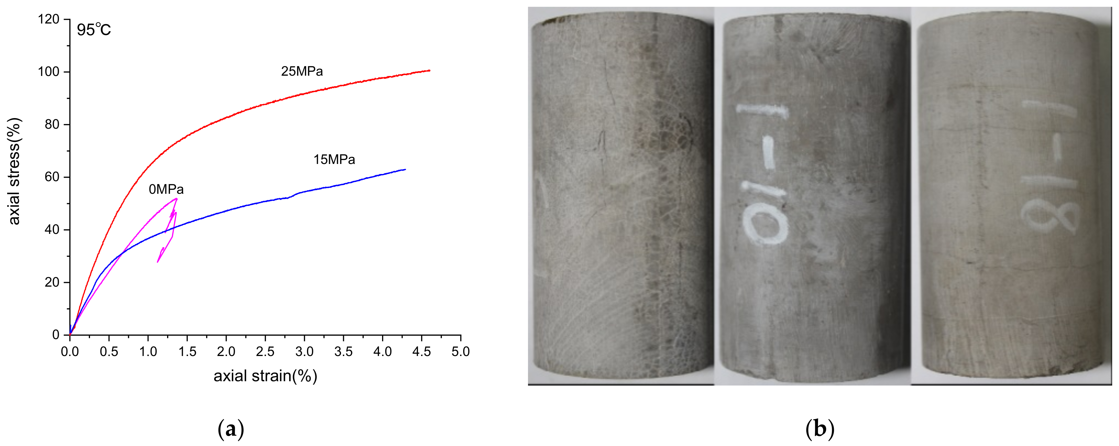
5.1. Samples Preparation

The samples were made of G-grade oil well cement, mixed with a certain proportion of silica powder (200 mesh), fluid loss reducer, SFP (a kind of cement admixture) and water. It is a formula suitable for high temperature formation. The detailed proportion is shown in Table 1. Then, the resulting cement paste was poured and molded in a cylindrical mold. In order to simulate the temperature and pressure environment of cement hydration and hardening in the deep part of the ground, the specimens were maintained in a water bath at a temperature of 130 °C and a pressure of 20.7 MPa for 72 h, and after maintenance, they were cooled in a water bath at 27 °C ± 3 °C and stored.
After the specimen maintenance is completed and demolded, further processing is required to ensure that: 1. the error of non-parallelism of both ends of the specimen is not more than 0.05 mm, 2. along the height of the specimen, the error of the diameter is not more than 0.3 mm, 3. the end face is perpendicular to the axis of the specimen, the maximum deviation is not more than 0.25°.

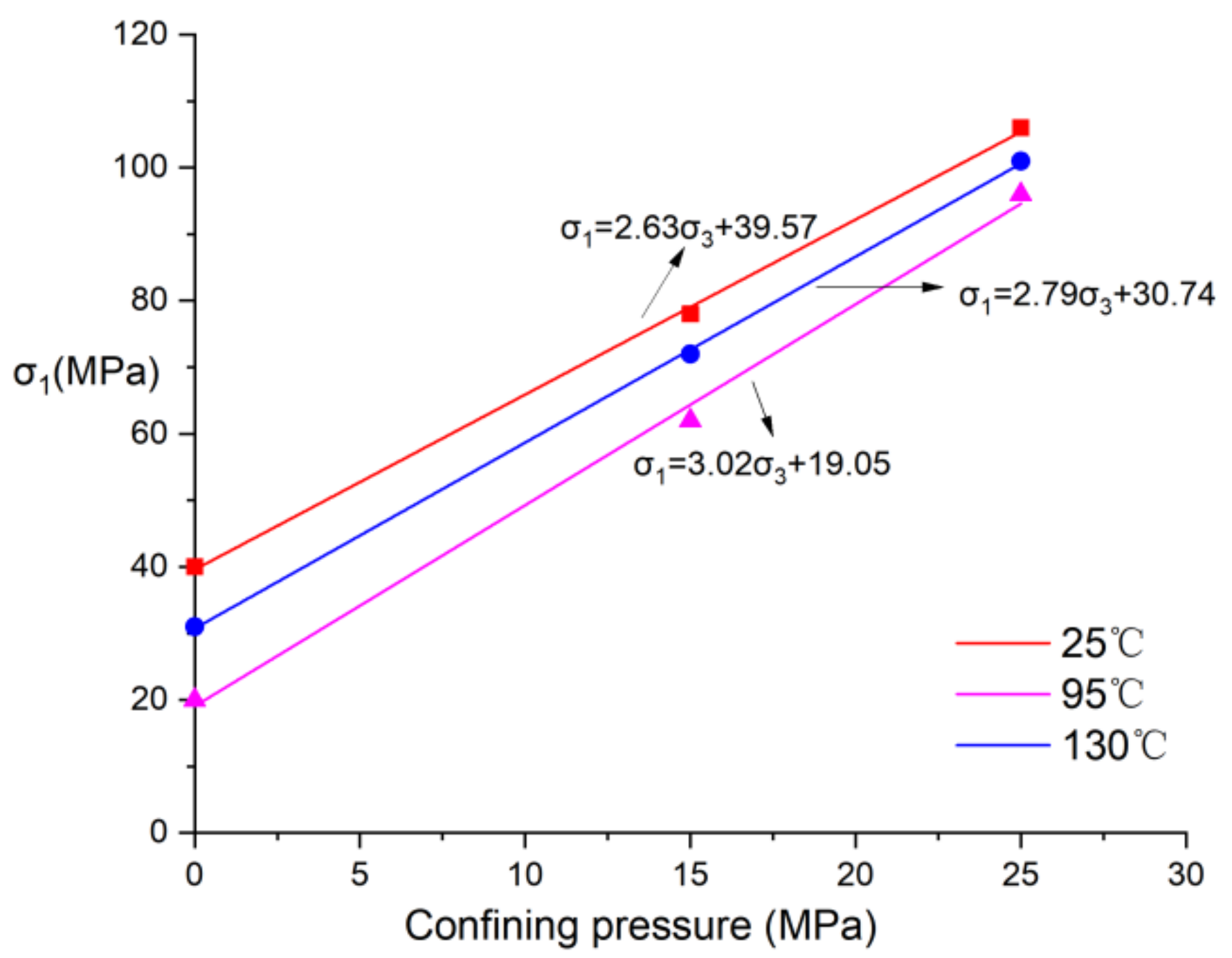
5.2. Tests Results and Analysis

The specimens were subjected to compression experiments at different temperatures of 25.95 and 130 °C. The test parameters and results are shown in Table 2. The stress–strain curves of the experiments and the damage morphology of the specimens are shown in Figure 2, Figure 3 and Figure 4.
The relationship between compressive strength σ1 and confining pressure σ3 is established according to the experimental results as shown in Figure 5, through which the cohesion and internal friction angle of sheath at different temperatures can be calculated using Equations (22) and (23).
φ = a r c s i n k 1 k + 1
c = σ c 1 s i n φ 2 c o s φ
where k is the slope of the fitted curve and σc is the intercept of the fitted curve.
The results of the fitted junction are shown in Table 2, plotted as a scatter plot and fitted with a simple quadratic curve in the Figure 6, the approximate laws of cohesion and internal friction angle of sheath with temperature can be roughly obtained.
The cohesion reflects the mutual attraction between adjacent parts within the stone, and it is a manifestation of molecular forces between the same substance. It can be seen from Table 3 and Figure 6 that, with the increase of temperature, the cohesion c of sheath tends to be downward. The cohesion is 12.20 MPa at 25 °C, 9.20 MPa at 95 °C, and 8.67 MPa at 130 °C and decreases by 24.59% and 28.93% compared with the normal temperature. This indicates that high temperature reduces the intermolecular attraction force inside the cement and makes the connection decline. That is similar to Bitouri’s result [36].
The internal friction angle φ reflects the internal friction between the particles in the rock, including the sliding friction caused by the roughness of the particle surface and the occlusal friction caused by the movement of particles due to the embedding, interlocking and disengagement of particles. As shown in Figure 6 and Table 3, the internal friction angle of the cement is 26.68° at room temperature, 28.17° at 95 °C, and 30.13° at 130 °C, which are 5.58% and 12.93% higher than that at room temperature respectively. This indicates that although the high temperature causes the connection of the cement to become relatively loose, the frictional resistance inside the cement increases relatively. Due to the great difference in composition, this result is opposite to Bitouri’s [36].
Under uniaxial condition, the failure mode of cement is tensile failure. With the increase of temperature, the strength of cement decreases, but its plastic properties gradually appear. With the increase of pressure, the samples mainly have axial compression deformation, and the lateral expansion is small. After the test, no macro-cracks are observed on the sample surface, which shows a good ability to resist deformation and failure. The value of σ1σ3 is in accordance with 2% of the plastic strain and σ1 is the compressive strength. Combined with the stress–strain curve, it can be seen that the cement has strong ideal elastic–plastic characteristics, which also verifies the accuracy of the cement mechanical model.

6. Analysis Based on Multiple Factors

Equation (18) shows that the effect of temperature on the maximum cyclic load of the sheath is reflected in two aspects; first, the change of temperature can be seen as a load on the sheath, namely the magnitude of γ. Second, with the change of temperature, the main material characteristics of the sheath is not immutable.
  • When temperature alone acts:
When downhole non-fracturing operations such as water injection, acidification, hole filling, etc. are carried out, the sheath is only subjected to periodic temperature variations. According to Formula (11), the critical value of the sheath during the temperature cyclic variation is calculated by the shakedown theory. It is found that the order of ΔT is 103, far from possible to make the sheath yield only at the temperature changes. Therefore, it is not necessary to consider the influence of individual temperature factors on the sheath in all procedures.
  • When fracturing and temperature cycling act simultaneously:
    (1)
    The case of temperature as stress
Equation (19) can be used to express that the negative effect of temperature change is related to the elasticity modulus, Poisson’s ratio, linear expansion coefficient and temperature difference of the cement. From the previous compression tests, the elasticity modulus ranges from 4 to 10 GPa, Poisson’s ratio ranges from 0.19 to 0.06, and the coefficient of thermal expansion of cement is about 1.5 × 10⁻⁵/°C. The variation range of the above-related material parameters is limited, the influence of them on the deep well environment is not maximal. For deep wells or ultra-deep wells, the temperature difference may reach 100 °C or higher and is the most important factor.
With the hike of temperature, as shown in Figure 7, the γ gradually increases. When the ΔT is from 60 to 110 °C, γ rises from 5.28 to 9.68 MPa, increasing by 83.33%. However, the external pressure P0 and the temperature increase with the increase of depth, and the external pressure plays a positive role in controlling the deformation of cement sheath. Therefore, although γ varies greatly with depth, the impact is limited, as shown in Figure 8. The negative impacts account for 6–7% of the Pmax, slowly increasing with depth.
(2)
The influence of temperature on the properties of cement materials:
Some researchers, such as Xu [4], analyze with the perspective of a stress state and do not involve material properties. However, as the depth increases, the formation temperature gradually rises, material properties of the cement will change, and its cohesion declines and the internal friction angle goes up, which directly affects the maximum cyclic stress (Pmax) of the sheath. The effect of temperature change on the Pmax is roughly calculated according to the fitting equations of cohesion and internal friction angle of cement in Section 7.
The in-depth extension magnifies the maximum cycle, regardless of the change of cement material properties, as shown in Figure 9. This is because the growing of depth will heighten the external pressure, which can protect the sheath. However, since the material properties are affected by temperature, the curve considering material damage is always below the red one without considering material property damage. That indicates that the Pmax is weakened due to the change of cement properties. After subtracting the two, as shown in Figure 10, it is found that the difference shows a non-linear increase with the temperature difference and its growth trend gradually slowing down.
(3)
The result of the combined effect of temperature:
In practical engineering, the influence of temperature on cement sheath is the combination of temperature stress and material property influence. It can comprehensively reflect the dynamic effects of temperature on cement sheath; however, it can provide a reliable reference for engineers.
The effect of temperature stress and material properties on the total maximum cycle load Pmax of the sheath rises with the temperature difference, as shown in Figure 11, the temperature-induced reduction of the bearing capacity accounts for 10–12% of the total bearing capacity of the sheath.

7. An Engineering Example

The J well, with an altitude of 734 m in Fuling, Chongqing, is a conductor hole (vertical well) with horizontal well. The target formation is the shale gas reservoir in the lower part of Upper Ordovician Wufeng Formation and lower Liuzhou Longmaxi formation. After inspection, the cementing quality of each casing and well section is qualified
From 25 November 2015 to 19 December 2015, a total of 27 sections of the shale gas well were fractured. The first section to the 27th section has an inclination angle of about 15° and the depth range is 3533–5530 m. According to the relevant geological data, the remaining parameters (see Table 4 below) are obtained for the calculation. The formation temperature gradient is 3 °C/100 m, and the rock mechanical parameters of cement and their variation pattern with temperature are obtained based on the present formula system. Except for the 8th, 9th and 11th fracturing sections, the maximum average operating pressure of each section is within their respective theoretical load range. The calculated safety loads of the 8th, 9th and 11th fracturing sections are 96.6, 95.85, and 91.55 MPa, and the actual operating pressures are 108.1, 106.3, and 97.23 MPa, which are respectively 10.21%, 10.09%, and 6.15% higher than the theoretical values. Therefore, in the 8th, 9th and 11th fracturing section, it is likely that after multiple fracturing, the stress state of cement will exceed the yield state, which will lead to large plastic deformation and cementing failure.
According to field observation, after a series of fracturing operations, the J well annulus sealing problems came out. Therefore, to a certain extent, it can be verified that the analysis method has a certain reference value.

8. Conclusions

According to the actual engineering problems, this paper establishes a mechanical model of the cement sheath based on the properties of cement and the actual engineering practice. In addition, shakedown theory is conducted on the sheath, combining the compression experiments under different conditions. Thus, the influence of temperature on the sheath has been clarified. Based on the present cement formula system and geological environment, we can conclude:
1.
When only the temperature inside the sheath varies cyclically, the range of cyclical changes in temperature brought about by the operation process has a negligible effect on the sheath.
2.
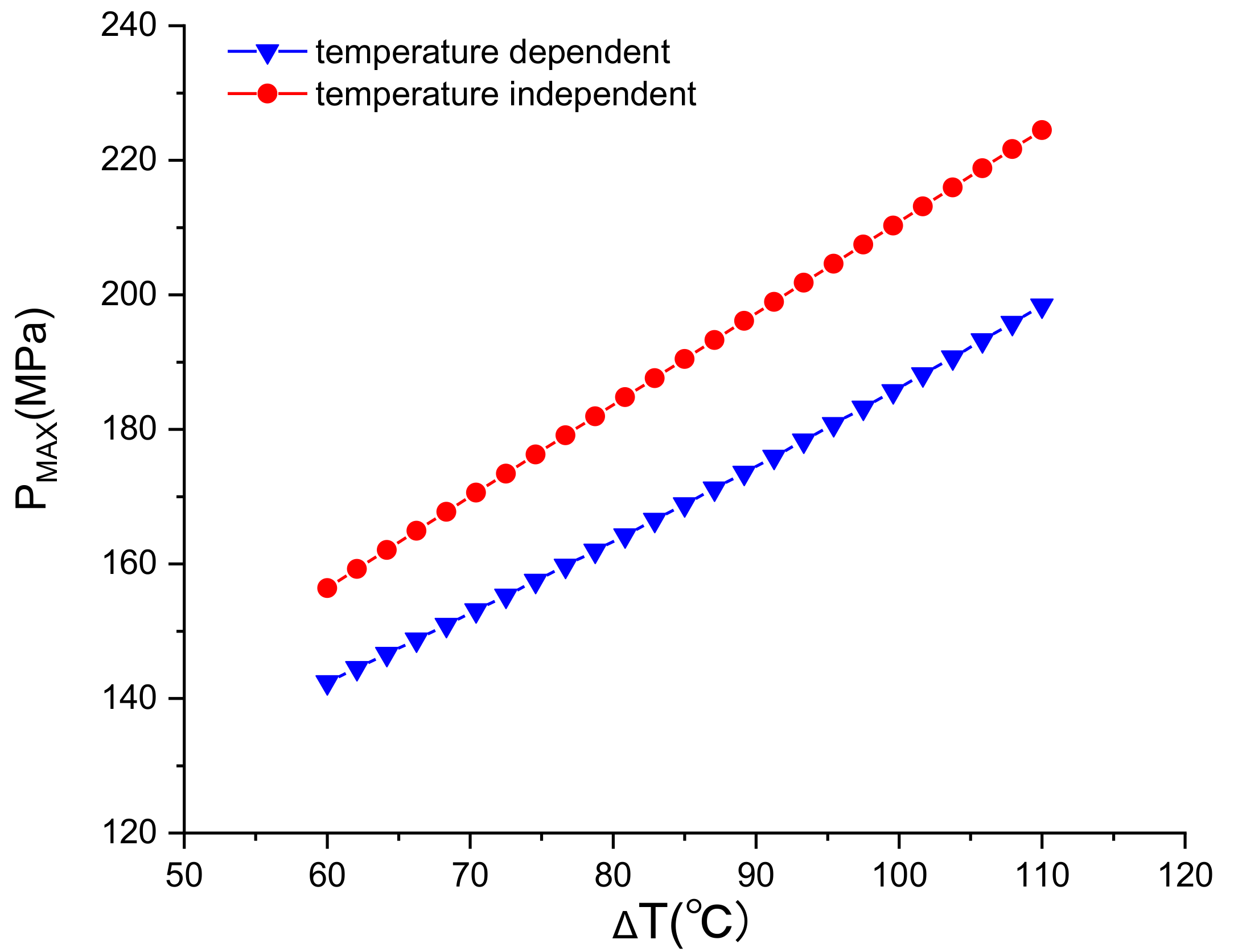
When the fracturing pressure and temperature act together on the sheath, the effect of temperature on it is reflected in two aspects. The temperature stress due to the existence of the difference between the internal and external surface causes the maximum cyclic load declining; however, the change in temperature causes the material parameters of the cement to change.
3.
The effect of temperature stress on sheath is proportional to the ∆T. The larger the temperature difference is, the greater the γ is. When the ∆T ranges from 70 to 110 °C, the negative effect of temperature stress on the total stress accounts for about 6–7%.
4.
The influence of temperature on the material properties of cement is as follows: with the rising of temperature, the cohesion of cement declines, and the internal friction angle increases. The plastic characteristics of the cement can be enhanced. With the change of ∆T, the negative effect of the Pmax ascends slowly.
5.
Comprehensive consideration of the role of temperature on the sheath, their total bad impact grows with the increase of the temperature difference. In the range of 60 to 110 °C, the temperature-induced reduction of the bearing capacity accounted for 10% to 12% of the total bearing capacity of the sheath. Therefore, during fracturing design, the engineer should reasonably design the fracture scheme according to the formation temperature and the characteristics of the cement.

Author Contributions

Conceptualization, X.Z. and Y.G.; methodology, L.W. and C.Y.; formal analysis, Z.B. and X.C.; resources, H.Y.; data curation, X.Z.; writing—original draft preparation, X.Z.; writing—review and editing, Y.G. All authors have read and agreed to the published version of the manuscript.

Funding

This research was sponsored by the “National Natural Science Foundation of China” (52104010) and the“Sinopec Science and Technology Department Project” (P21056).

Institutional Review Board Statement

Not applicable.

Informed Consent Statement

Not applicable.

Data Availability Statement

Not applicable.

Conflicts of Interest

The authors declare no conflict of interest.

References

  1. Shadravan, A.; Schubert, J.; Amani, M.; Teodoriu, C. HPHT cement sheath integrity evaluation method for unconventional wells. In Proceedings of the SPE International Conference on Health, Safety, and Environment, Long Beach, CA, USA, 17–19 March 2014. [Google Scholar]
  2. Wang, W.; Taleghani, A.D. Cement sheath integrity during hydraulic fracturing: An integrated modeling approach. In Proceedings of the SPE Hydraulic Fracturing Technology Conference, The Woodlands, TX, USA, 4–6 February 2014. [Google Scholar]
  3. Vrålstad, T.; Skorpa, R.; Opedal, N.; Andrade, J.D. Effect of thermal cycling on cement sheath integrity: Realistic experimental tests and simulation of resulting leakages. In Proceedings of the SPE Thermal Well Integrity and Design Symposium, Banff, AB, Canada, 23–25 November 2015. [Google Scholar]
  4. Xu, H.; Peng, N.; Ma, T.; Yang, B. Investigation of thermal stress of cement sheath for geothermal wells during fracturing. Energies 2018, 11, 2581. [Google Scholar] [CrossRef] [Green Version]
  5. Wang, L.; Zeng, Y.J.; Zhang, Q.Q. Experimental study on mechanical properties of oil well cement under high temperature. J. China Univ. Pet. 2018, 42, 88–95. [Google Scholar]
  6. Lian, W.; Li, J.; Tao, Q.; Du, J.; Wang, L.; Xi, Y. Formation mechanism of continuous gas leakage paths in cement sheath during hydraulic fracturing. Energy Sci. Eng. 2020, 8, 2527–2547. [Google Scholar] [CrossRef] [Green Version]
  7. Yang, L.I.U.; Zhengqing, A.I.; Zaoyuan, L.I.; Xiaoyang, G. Discussion on the Influence Factors of Cementing Circulating Temperature. J. Southwest Pet. Univ. (Sci. Technol. Ed.) 2012, 34, 154–158. [Google Scholar]
  8. Kuanhai, D.; Xie, P.; Yue, Y.; Dezhi, Z.; Qiong, L.; Yuanhua, L. Study on the effect of interface failure between casing and cement sheath on casing stress under non-uniform in-situ stress. Appl. Math. Model. 2021, 91, 632–652. [Google Scholar] [CrossRef]
  9. Zhao, H.; Wen, D. Study on influencing factors of temperature field distribution in deep water cementing. Shipbuild. China 2019, 60, 135–145. [Google Scholar]
  10. Kruszewski, M.; Montegrossi, G.; Ramírez Montes, M.; Wittig, V.; Gomez Garcia, A.; Sánchez Luviano, M.; Bracke, R. A wellbore cement sheath damage prediction model with the integration of acoustic wellbore measurements. Geothermics 2019, 80, 195–207. [Google Scholar] [CrossRef]
  11. Wang, C.; Liu, S.; Zhai, Y.; Qu, Y.; Wen, M. Discussion on circulating temperature during cementing. Nat. Gas Explor. Dev. 2015, 38, 70–76. [Google Scholar]
  12. Yu, Y.; Ding, Z.; Zhang, C.; Zhang, H.; Guo, J. A cement slurry used at ultra-high circulation temperature of 210 °C. Drill. Fluid Completion Fluid 2019, 36, 349–354. [Google Scholar]
  13. Ye, Z.; Zhu, Z.; Wu, P.; Liu, W.; Xu, Z. The influence of temperature, pressure and pH value on cement curing. China Cem. 2010, 11, 58–62. [Google Scholar]
  14. Li, Q.H.; Yao, Y.; Sun, B.; Li, Z.J. Investigation on behavior of thermal expansion of hydraulic cement paste. J. Build. Mater. 2007, 6, 631–635. [Google Scholar]
  15. Deng, K.; Liu, W.; Liu, B.; Lin, Y.; Singh, A. Repairing force for deformed casing shaping with spinning casing swage and damage behaviour of cement sheath. Appl. Math. Model. 2019, 70, 425–438. [Google Scholar] [CrossRef]
  16. Walske, M.L.; McWilliam, H.; Doherty, J.; Fourie, A. Influence of curing temperature and stress conditions on mechanical properties of cementing paste backfill. Can. Geotech. J. 2015, 53, 88–95. [Google Scholar] [CrossRef]
  17. Gao, B. The mechanism of radial separation of cement sheath and casing during temperature cycling. Pet. Sci. 2006, 3, 45–50. [Google Scholar]
  18. Al-Yami, A.S.; Wagle, V.B.; Abdurrahman, R.; Taoutaou, S. Engineered fit-for-purpose cement system to withstand life-of-the-well pressure and temperature cycling. J. China Univ. Pet. 2018, 42, 88–95. [Google Scholar]
  19. Sabins, F. Ultra-Lightweight Cement; Office of Scientific & Technical Information Technical Reports; Department of Energy (DOE) Office: Texas, TX, USA, 2002. [Google Scholar]
  20. Wang, C.; Chen, X.; Zhou, W.; Wang, Y.; Xue, Y.; Luo, F. Working mechanism of nano-SiO2 sol to alleviate the strength declineof oil well cement under high temperature. Nat. Gas Ind. 2019, 6, 517–523. [Google Scholar] [CrossRef]
  21. Wu, Y.; Patel, H.; Salehi, S. Parametric study of mechanical stresses within cement sheath in geothermal wells. Geothermics 2021, 90, 102000. [Google Scholar] [CrossRef]
  22. Kuanhai, D.; Wanying, L.; Tianguo, X.; Dezhi, Z.; Ming, L.; Yuanhua, L. Experimental study the collapse failure mechanism of cemented casing under non-uniform load. Eng. Fail. Anal. 2017, 73, 1–10. [Google Scholar] [CrossRef]
  23. Zheng, Y.; Xu, B.; Pu, J.; Li, M.; Wang, B. Mechanical behavior of cementing system under different conditions. Nat. Gas Ind. 2017, 37, 119–123. [Google Scholar]
  24. Park, M.; Min, S.; Lim, J.; Choi, J.M.; Choi, H. Applicability of cement-based grout for ground heat exchanger considering heating-cooling cycles. Sci. China Technol. Sci. 2018, 7, 1661–1667. [Google Scholar] [CrossRef]
  25. Hager, I. Behaviour of cement concrete at high temperature. Bull. Pol. Acad. Sci. Tech. Sci. 2013, 61, 145–154. [Google Scholar] [CrossRef]
  26. Patel, H.; Salehi, S. Structural integrity of liner cement in oil & gas wells: Parametric study, sensitivity analysis, and risk assessment. Eng. Fail. Anal. 2021, 122, 105203. [Google Scholar] [CrossRef]
  27. De Andrade, J.; Sangesland, S. Cement sheath failure mechanisms: Numerical estimates to design for long-term well integrity. J. Pet. Sci. Eng. 2016, 147, 682–698. [Google Scholar] [CrossRef]
  28. Zhou, S.; Liu, R.; Zeng, H.; Zeng, Y.; Zhang, L.; Zhang, J.; Li, X. Mechanical characteristics of well cement under cyclic loading and its influence on the integrity of shale gas wellbores. Fuel 2019, 250, 132–143. [Google Scholar] [CrossRef]
  29. Arjomand, E.; Bennett, T.; Nguyen, G.D. Evaluation of cement sheath integrity subject to enhanced pressure. J. Pet. Sci. Eng. 2018, 170, 1–13. [Google Scholar] [CrossRef]
  30. Bois, A.-P.; Garnier, A.; Galdiolo, G.; Laudet, J.-B.; Total, S.A. Use of a mechanistic model to forecast cement-sheath integrity. SPE Drill. Complet. 2012, 27, 303–314. [Google Scholar] [CrossRef]
  31. Yan, X.; Jun, L.; Gonghui, L.; Qian, T.; Wei, L. A new numerical investigation of cement sheath integrity during multistage hydraulic fracturing shale gas wells. J. Nat. Gas Sci. Eng. 2018, 49, 331–341. [Google Scholar] [CrossRef]
  32. Koiter, W.T. General theorems for elastic-plastic solids. Prog. Solid Mech. 1960, 6, 167–221. [Google Scholar]
  33. Melan, E. Theorie statisch unbestimmter systeme aus idealplasticschen baustoff. Sitz. Akad. Wiss. 1938, 195, 145–195. [Google Scholar]
  34. Neal, B.G. The Plastic Methods of Structural Analysis; Chapman and Hall Ltd.: London, UK, 1956. [Google Scholar]
  35. Zarka, J.; Casier, J. Cyclic loading on elastic-plastic structures. Mech. Today 1979, 6, 93–198. [Google Scholar]
  36. El Bitouri, Y.; Jamin, F.; Pélissou, C.; El Youssoufi, M.S. Tensile and shear bond strength between cement paste and aggregate subjected to high temperature. Mater. Struct. 2017, 50, 234. [Google Scholar] [CrossRef] [Green Version]
Figure 1. Schematic diagram of cement sheath model.
Energies 14 07162 g001
Figure 2. Compression test at 25 °C. (a) Stress–strain curves; (b) samples morphology after test.
Energies 14 07162 g002
Figure 3. Compression test at 95 °C (a) Stress–strain curves; (b) samples morphology after test.
Energies 14 07162 g003
Figure 4. Compression test at 130 °C (a) Stress–strain curves; (b) samples morphology after test.
Energies 14 07162 g004
Figure 5. Fitting curve of confining pressure and σ1 at different temperatures.
Energies 14 07162 g005
Figure 6. The relationship between cohesion, internal friction angle and temperature.
Energies 14 07162 g006
Figure 7. The relationship between temperature difference and γ.
Energies 14 07162 g007
Figure 8. The relationship between temperature difference and γ/PMAX.
Energies 14 07162 g008
Figure 9. The influence of temperature on material properties.
Energies 14 07162 g009
Figure 10. The relationship between negative effect and temperature difference.
Energies 14 07162 g010
Figure 11. The total influence of temperature material properties on Pmax.
Energies 14 07162 g011
Table 1. Formula of cement slurry system.
Cement Slurry SystemFormula
High temperature and high-pressure resistant formulaG-grade oil well cement
35%SiO2 (silica powder)
6% SFP-1
4%DZJ-Y (fluid loss reducer)
0.2% SFP-2
42% H2O
Table 2. Specimen parameters and experimental results.
Sample NumberDiameter
(mm)
Height
(mm)
Confining Pressure
σ3(MPa)
σ1σ3
(MPa)
μE
(GPa)
Temperature
(°C)
C-1-249.8999.91039.800.1524.8525
C-1-750.01100.071563.230.1336.8625
C-1-850.0699.852581.500.1219.9025
C-1-349.9299.85030.960.1244.3295
C-1-1049.89100.021556.890.1115.9695
C-1-1849.96100.022576.020.1038.1495
C-1-550.0799.94019.980.0973.01130
C-1-650.01100.001547.110.0753.96130
C-1-449.8999.932570.940.0625.81130
Table 3. Fitting parameters and results.
Temperature
(°C)
kσc
(MPa)
C
(MPa)
ϕ
(°)
252.6339.5712.2026.68
952.7930.749.2028.17
1303.0219.058.6730.13
Table 4. Related calculation parameters.
Casing ParametersEnvironmental ParametersStructure Parameters
E1 = 210 GPaDepth; 3533–5530 mai = 127.36 mm
bi = 139.7 mm
μ1 = 0.2P0 = 74–116 MPaa = 139.7 mm
b = 233.45 mm
Publisher’s Note: MDPI stays neutral with regard to jurisdictional claims in published maps and institutional affiliations.

