Abstract
One of the measures to fight against the current energy situation and reduce the energy consumption at an industrial process is to recover waste heat and transform it into electric power. Thermoelectric generators can be used for that purpose but there is a lack of experimental studies that can bring this technology closer to reality. This work presents the design, optimizations and development of two devices that are experimented and compared under the same working conditions. The hot side heat exchanger of both generators has been designed using a computational fluid dynamics software and for the cold side of the generators two technologies have been analysed: a finned dissipater that uses a fan and free convection biphasic thermosyphon. The results obtained show a maximum net generation of in the thermoelectric generator with the finned dissipater; and of power output in the generator with the biphasic thermosyphon. These results remark the importance of a proper design of the heat exchangers, trying to get low thermal resistances at both sides of the thermoelectric modules, as well as, the necessity of considering the auxiliary consumption of the equipment employed.
1. Introduction
The current global energy situation is pushing every activity to proper use of the resources. In this sense, it is quite common the implementation of energy efficiency measures in domestic and industrial processes. One of these measures is the recovery and reuse of the excess heat that is available in many activities, the so called waste heat [1].
There are plenty of examples about how to recover that waste heat. For instance: Sun presents an analysis to use waste energy from a gas turbine [2] and Kim proposes the use of an organic Rankine cycle to be employed at a thermal power plant and be able to produce electricity from a flue gas [3]. Other ideas include the use of that waste heat to increase the efficiency and environmental operation of a process by employing heat recuperators [4].
Several studies can be found in the literature that analyse the use of thermoelectric generators as a way of harvesting waste heat. These devices can convert thermal energy into electricity by placing a thermoelectric module in between a hot source and a heat sink. Meng et al. [5] theoretically study the production of up to of electric power from a hot gases stream at 350 achieving a generation efficiency of 4.5% for the generator and a return of investment of just 4 years. Yazawa et al. [6] propose the installation of thermoelectric generators in a glass melt factory, on the walls of the fusion furnace getting a theoretical electric production of . Araiz et al. [7] present a theoretical study about the installation of thermoelectric modules on the outer wall of a flue gas chimney to produce up to 45 of electric power after several parameters optimization.
All these works show the high potential of this technology for the harvest of waste heat energy. However, it is crucial to move from theoretical works to experimental analysis and build prototypes that show the real possibilities of thermoelectric generators. Nesarajah et al. [8] have built a 2 prototype to harvest waste heat from a hot gas current. Chiarotti et al. [9] show an example of a thermoelectric generator that is able to produce up to 36 of electric power using a water flow at 90 as the heat source. This study includes the consumption of the auxiliary equipment used on the cold side of the generator, leading to a decrease in the net production to 20 . Børset et al. [10] present a thermoelectric generator employed in a metal casting plant that absorbs the heat by radiation from a heat source at 1400 producing up to 160 / of electric output. Although these experimental works are really important to validate the results obtained from theoretical analysis, there is a lack of optimization of the heat exchangers at both sides of the thermoelectric modules and only some of them take into account the auxiliary consumption of the equipment employed for a proper operation of the heat exchangers. These two aspects are really important if a more practical use of thermoelectricity is sought.
The purpose of the heat exchangers is to bring the temperature of the hot and cold faces of the modules closer to the temperatures of the heat source and cold sink, respectively. In this way, by increasing the temperature difference between the faces of the modules, the electric power output is increased [11].
The design of the hot side heat exchangers plays a vital role in waste heat recovery processes. In some cases, the improvements achieved from the thermal and heat transfer point of view have some pressure losses associated with the hot current that needs to be considered [12]. One of the easiest ways to enhance heat transfer from a hot gas current is to extend the surface available [13]. In most cases, these extended surfaces consist of flat metal fins placed longitudinally inside the duct, other studies have studied the use of pin fins in flows where the Reynolds number is low [14]. There are other alternatives such as the use of metal foams to fill in the duct where the gases are flowing to increase the exchange area and the mixing capability of the fluid [15] and seem to perform better compared to traditional fin dissipaters [16]. However, when applied to thermoelectric generators, where the auxiliary consumption is crucial, the pressure losses that cause this kind of heat exchanger are greatly increased [17]. The use of phase-change heat exchangers on the hot side has also been analysed but it raises the cost of the whole installation and affects significantly the proper flow of the hot current [18,19].
Concerning the cold side heat exchangers, there is also a wide range of options to be considered in this part of the thermoelectric generators. Martinez et al. [20] explain that finned dissipaters are widely used due to their simplicity and low cost and working as active heat exchangers using a fan they can achieve high heat transfer rates. Tzeng et al. [21] propose the use of finned dissipaters at both sides of 4 thermoelectric modules to harvest waste heat from an exit fumes current being able to produce 12 . However, the auxiliary consumption of the fans is not considered. Kim et al. [22] employ liquid water heat exchangers at the cold side of a thermoelectric generator getting better heat transfer coefficients and increasing, in this sense, the efficiency of the device. The maximum power output obtained from this system reaches 119 with 40 thermoelectric modules. But again, here the consumption of the pump that moves the water inside the cold side heat exchanger is not taken into account [23]. Aranguren et al. [24] performed a deep study about the influence of the auxiliary equipment needed in this kind of heat exchangers, considering not only the extra consumption of the pump but also the heat exchangers necessary to remove the heat from the water to the ambient. Finally, an optimization of the whole thermoelectric generator was achieved.
Biphasic heat exchangers, working with fluids in vapour-liquid states, are also employed for the cold side of a thermoelectric generator because heat transfer rates are even higher with these systems. Date et al. [25] compared a heat-pipe with a finned dissipater as the cold side heat exchanger in a thermoelectric generator and was able to produce four times more power using the biphasic device, . In this study and many others that use biphasic devices like the one performed by Remeli et al. [26], a fan is employed to release the heat from the condenser to the environment, that is why the extra consumption must be carefully analysed.
According to the literature review, a proper optimization of the heat exchangers that accompany the thermoelectric modules at both sides of the generator is crucial to the performance of the device. It is vital to consider the auxiliary consumption of the equipment that may be involved in them as well. This work presents the design, optimization and experimentation of two thermoelectric generators for waste heat recovery from a combustion chamber. For the hot side heat exchangers, fins have been considered and a CFD study has been done considering the thermal performance of the fins as well as the pressure losses that are added when including them. For the cold side, two technologies have been investigated: a finned dissipater with a fan, which is widely employed in thermoelectric applications; and a biphasic thermosyphon with free-convection, a phase change device that can operate with no extra consumption. The idea is to test and compare both technologies in the exact same working conditions. Section 2 presents the application where waste heat is being recovered and the methodology followed to analyse the generators; Section 3 describes the design and optimization of the prototypes of thermoelectric generators; and, finally, Section 4 shows the results obtained from the experimentation. The electric power output and the thermal resistances of the thermoelectric generators are studied for different conditions: load resistance, auxiliary consumption and mass flow of the hot gases.
2. Methodology
The purpose of this work is to build and experimentally test how a thermoelectric generator can be used for waste heat recovery. As it has been explained before, it is essential an optimization of both, cold and hot heat exchangers of a thermoelectric generator system. Therefore, it is really important to develop a methodology that enables us to analyse the behaviour of the entire system. The methodology must be simple and ready to incorporate both analytical and experimental results that allows an understanding of the performance of the generator. In this application, for the hot side, fins have been chosen to be attached to the interior part of the duct, enhancing the heat transfer from the hot gases to the wall of the duct.
For the cold side of the thermoelectric generator, two technologies are investigated: a finned heat sink, notable for its simplicity, commercial availability and relatively low cost; and a biphasic thermosyphon heat exchanger, which, when operating under free convection, is a completely passive system and, despite its more complexity, can improve the whole performance of the thermoelectric system [27]. One of the goals of this work is to compare both systems and check the differences between them working on the same operating conditions.
2.1. Waste Heat Recovery Application
The experimental setup recovers waste heat from a water boiler located in the Laboratories of the Public University of Navarre. This system uses natural gas as fuel and the comburant, air, is introduced to the combustion chamber using a YP3 blower [28]. It can operate with a fuel mass flow between 2.2 kg/h and 19.4 /; an air mass flow between 50 and 160 ; and can produce a warm water flow rate between 500 kg/h and 1800 /. The flue of the boiler consists of an elbow joint that connects the combustion chamber with a vertical round duct that releases the hot gases out to the atmosphere through the roof of the laboratory.
This exit duct is modified to a flat wall duct enabling the installation of thermoelectric modules to recover the waste heat carried by the hot gases. On the inner part of the duct, the hot side heat exchangers will be placed, whereas on the outer side of the duct two kinds of cold side heat exchangers will be investigated.
2.2. Analysis Methodology
In order to properly analyse the results obtained from the experimental tests, a calculation methodology has been developed to explain the thermal behaviour of the elements that form the thermoelectric generator. The idea is to determine the thermal resistances of the components of the system and estimate the heat fluxes that are flowing through them. This tool would help to describe all thermal phenomena that happen along with the thermoelectric generator as well as analysing all the experimental results obtained from the prototype.
According to Figure 1 the hot gases suffer a temperature drop as they flow inside the duct where the thermoelectric generators are placed. This enthalpy drop can be estimated using Equation (1) and part of the energy is absorbed by the TEG and the rest is released to the ambient as a heat loss through the wall, see Equation (2).
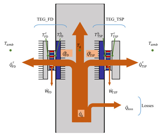
Figure 1.
Scheme of the methodology to estimate thermal resistances and heat fluxes.
Part of the heat that flows through the thermoelectric modules is converted into electricity, whereas the rest must be released to the ambient, as shown in Equations (3) and (4).
After the experimental tests, knowing the temperature of several points of the device, as well as the mass flow of the hot gases, the enthalpy variation that suffers this flow can be obtained, , with Equation (1). Besides, using the voltage and current values from the thermoelectric generators, the electric power output of them can be determined using Equations (5) and (6).
Moreover, the thermosyphon heat exchanger used in one of the thermoelectric generators has been characterised (see Section 3.2) to obtain the thermal resistance of the device as a function of the heat flux dissipated, . After an iterative calculation, the thermal resistance of the system, ; the heat flux released to the ambient, ; and, using Equation (3), the heat flux absorbed by this TEG, , can be estimated. With this result, the hot face temperature of the TE modules, ; and the temperature of the hot gases, ; the thermal resistance of the hot side heat exchanger can be determined, see Equation (7).
It has been assumed that both hot side heat exchangers are equal, so their thermal resistance has the same value since the thermal behaviour of a finned dissipater is hardly affected by the heat flux [29]. Therefore, the heat absorbed by the thermoelectric generator using the finned dissipater on its cold side can be estimated using Equation (8).
3. TEG Design
This section includes the design and building of the heat exchangers of both sides that form the thermoelectric generator. It also includes the assembly of the whole prototypes and the installation at the exhaust pipe of the boiler described in Section 2.1. The requirements followed for the design of these devices include the possibility to operate in a real application during extended periods and they must be compact enough to install several of these systems to recover that waste heat source. In this way, if the system is applied to a larger scale, the very same design could be used to ensure a proper behaviour of the device.
3.1. Hot Side Heat Exchanger
The goal of the hot side heat exchanger is to bring the temperature of the hot face of the thermoelectric modules closer to the temperature of the hot gases that flow inside the exhaust duct. Due to the simplicity and adaptability to different geometries, a finned dissipater has been chosen for this task. It is now necessary to optimize the design of the heat sink, considering the thermal behaviour of the device, as well as the influence of these fins inside the exhaust pipe. A computational model, using the fluid dynamics software ANSYS Fluent, has been used to analyse heat transfer phenomena and flow performance for different geometries under several boundary conditions. This model was developed in a previous work by Aranguren et al. [29] where it was validated and an independence mesh study was performed. It is a 3D model that employs the realizable turbulence model and can successfully simulate the thermal and fluid behaviour of a hot gas current.
Figure 2 shows the different geometries studied with the computational model. Case A represents a basic inner pipe with flat surfaces and no elements that could enhance heat transfer between the hot gases and the thermoelectric modules. Case B includes long fins longitudinally placed inside the duct which are 35 heigh and are 21 spaced. The objective of these flat plates is to increase the turbulence of the gases flow and to extend the heat transfer area. With the aim of rising the turbulence, even more, short fins have been also studied in two configurations: aligned, Case C; and misaligned, Case D. In this latter case, the exchange area is equal to the surface offered by Case B, so this design will be useful to analyse the influence of the turbulence increase for the same exchange surface.
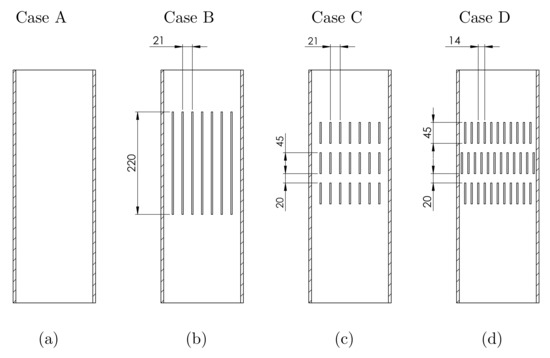
Figure 2.
Geometries analysed for the hot side heat-exchanger. (a) Flat inner surface; (b) Long fins; (c) Short aligned fins; and (d) Short misaligned fins.
All the geometries have been included in the CFD software and properly meshed to represent the velocity and temperature boundary layers of the hot exhaust gases. The boundary conditions used are shown in Figure 3: velocity inlet, which includes the velocity and inlet temperature of the hot gases; walls, for the surface of the pipe distinguishing the adiabatic zones and the ones converted by thermoelectric modules, where heat flux, , is absorbed; pressure outlet to state the exit of the fumes. Once each of the four geometries is meshed the simulations have been carried out varying the inlet temperature, 490 °C, 525 °C and 560 ; and the mass flow of the gases, 100 kg/h, 133 kg/h and 170 /, reproducing the conditions that can be obtained from the experimentation.
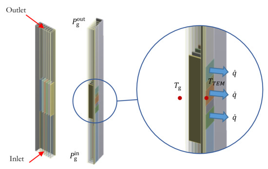
Figure 3.
Boundary conditions used in the ANSYS Fluent simulations.
The objective of these simulations is to check the performance of each heat exchanger by estimating the thermal resistance between the hot fumes and the external wall of the duct, where the thermoelectric modules would be placed; and determining the pressure drop caused between the inlet and outlet of the pipe. The thermal resistance of the hot heat exchanger is calculated using Equation (10), where is the temperature of the hot gases; and the temperature of the outer wall of the duct where the thermoelectric modules are placed. The pressure losses are estimated using Equation (11) and the pressure of the gases at the inlet and outlet of the pipe, and respectively.
Figure 4 shows the velocity diagram of one of the simulations run with ANSYS Fluent where the effect of using fins inside the pipe seems significant over the turbulence of the flow. This diagram has been extracted from a vertical cut section inside the duct at a middle point of the fins added.
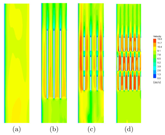
Figure 4.
Velocity diagram at a vertical cut section inside the duct after the simulations with a gases temperature of 490 and a mass flow of 100 /. (a) Flat inner surface; (b) Long fins; (c) Short aligned fins; and (d) Short misaligned fins.
The results for the thermal resistance of the hot side heat exchanger are presented in Figure 5 as a function of the mass flow. In all the configurations studied the thermal resistance decreases as the mass flow increases due to the enhancement of the convective coefficients achieved by the rise of the gas velocity. Moreover, case A gets the worst thermal resistance results compared to other configurations that include fins inside. There are small differences between case B and C, since, although case B offers more exchange area, case C presents higher turbulence of the flow restarting the boundary layer and increasing the convective heat transfer coefficient. Case D, which has the same exchange area as case B, obtains better results for the thermal resistance because of the increase in the turbulence and the reduction of the fin spacing that speeds the gases up, enhancing the convective coefficients. As it can be seen, the influence of the temperature of the gases is negligible over the thermal resistance for the ranges analysed.

Figure 5.
Thermal resistance of the hot side heat exchangers, between the exhaust gases and the hot face of the thermoelectric modules.
With regard to the pressure losses, there are also little differences of the behaviour of the heat exchangers with the temperature. Therefore, Figure 6 shows the pressure drop for the geometries considered for the simulation with the gases at an inlet temperature of 560 . The flat pipe, case A, has the lowest pressure losses among all the cases, as expected. For cases B and C the pressure drop is similar; and case D, with the reduction of the fin spacing, that increases the turbulences, the pressure losses increase drastically. Figure 6 also includes the curve of the blower installed in the boiler that pumps the air to the combustion chamber and helps the hot gases to be released to the atmosphere through the exhaust pipe. As this blower is going to be used for the experiments of the boiler with the thermoelectric generator, it should be able to overcome the pressure losses offered by the heat exchanger place inside the exhaust pipe.

Figure 6.
Blower curve and pressure losses caused by the different geometries of the heat exchangers analysed. Temperature of the hot gases 560 .
According to the results obtained from the simulations, it is essential to include fins inside the exhaust duct in order to greatly enhance heat transfer between the hot gases and the face of the thermoelectric modules. The thermal resistances of the hot side heat exchanger can be reduced from / or 4 / if the pipe were flat, to thermal resistances of 2 / by means of including these fins inside. Despite the low thermal resistance achieved in case D, this design has been rejected due to its high pressure drop, even over the blower curve for the mass flows range studied. Case B and case C have similar thermal and hydraulic behaviour, however, case B design has been chosen for the hot side heat exchanger as it is easier to manufacture.
3.2. Cold Side Heat Exchangers
The cold side heat-exchangers’ objective is to help to release the heat that has not been converted to electricity by the thermoelectric modules to the atmosphere, and thus, increases the temperature difference between the the faces of the modules. There is a wide range of systems that can be employed as heat exchangers, in this study the devices considered are: a finned heat sink with forced convection and a biphasic thermosyphon under free convection. Finned dissipaters stand out thanks to their simplicity and commercial availability since they can be found in many geometries and configurations and are inexpensive compared to other technologies. However, they need a fan to make the air flow through their fins achieving an effective heat transfer. For this reason, this system is going to be compared to a biphasic thermosyphon with natural convection, which is a passive device, where no fans or pumps are needed. It is a more complex system but, as there is no auxiliary consumption, all the power output generated by the thermoelectric modules is usable.
The requirement for the design of the thermoelectric generator prototype is that it could be possible to be installed at a larger scale, therefore several devices could be used to harvest energy from the same waste heat source.
3.2.1. Finned Heat Sink
The finned dissipater chosen for the cold side heat exchanger for one of the thermoelectric generators has base thickness, a 150 × 225 rectangular base, the corrugated fins are high, thick and they are 6 spaced. This system has been designed according to previous works where finned heat sinks were employed as cold side heat exchangers in thermoelectric devices [30] and includes a Sunon MEC0251V1 fan to make the air flow between the fins.
3.2.2. Biphasic Thermosyphon under Free Convection
For the design of the other heat exchanger studied, the biphasic thermosyphon, a validated computational model previously developed has been employed [27]. This loop thermosyphon with water has an evaporator in contact with the thermoelectric modules. The heat released by them makes the fluid inside boil, this vapour flows through the vapour line up to the condenser. Once there, the vapour turns back into liquid as it releases the heat to the atmosphere and, due to the tilt angle of the condenser tubes, the liquid drains back to the evaporator, closing the loop, see Figure 7.

Figure 7.
Biphasic thermosyphon employed on one of the thermoelectric generators under free convection.
This device has a 150 × 225 rectangular base, similar to finned heat sink. As reported in the previous work, the most important part of such devices is the condensation section, that is why this thermosyphon has 18 parallel copper tubes, 2 long each, with an internal diameter of 7 . These tubes include external × 25 aluminium fins, with a thick which are 8 spaced to enhance free convection of the heat between the condenser and the ambient. The condenser has been split into two branches to provide a more compact prototype.
In this way, as it can be seen in Figure 8 and as it happens with the finned heat sink, this design allows the installation of multiple thermoelectric generators in the same exhaust duct. The condensers can be slightly separated from the duct to enable the evaporator of the following generator.
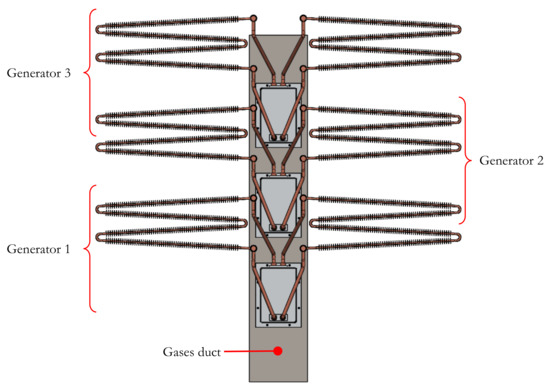
Figure 8.
Installation scheme of several thermoelectric generators with biphasic thermosyphons on the same exhaust duct.
Once the biphasic thermosyphon is built, it has been characterised to obtain the value of its thermal resistance, according to Equation (12), and be able to use the methodology explained before. For these experiments, electric resistances have been employed to simulate the heat that the device must release, ; temperature probes have been placed to measure the temperature at the evaporator section, ; and the ambient temperature, . The results obtained from the test are represented in Figure 9.

Figure 9.
Experimental characterization of the biphasic thermosyphon.
3.3. TEG Prototype
Once all the heat exchangers have been designed and built, the thermoelectric generators have been installed at the exhaust pipe of the boiler as Figure 10 shows. Both thermoelectric generators have identical hot side heat exchangers and have 6 thermoelectric modules each. The first prototype uses the finned heat sink as the cold side heat exchanger, TEG_FD; whereas the other prototype employs the biphasic thermosyphon with free convection, TEG_TSP. Both prototypes are placed at the same point of the pipe, and the idea is to compare the power output and efficiency of these devices under the exact same working conditions.

Figure 10.
Thermoelectric generators built and installed at the exhaust pipe of the boiler. Scheme of the parts that form the prototypes and their assembly.
Both thermoelectric generators have been installed with several probes and sensors to properly monitor the behaviour of them registering values of temperature, mass flow, voltage and current. Figure 11 shows the distribution of the sensors employed which is as follows: 16 temperature probes to register hot and cold face temperature of 8 thermoelectric modules; 6 sensors for inlet and outlet temperature of the hot gases and determine the temperature drop of the fumes across the generators; 2 ambient temperature probes; 2 sensors to determine the temperature of the wall of the insulation and estimate the heat losses; 1 mass flow meter; 2 voltmeters; and 2 ammeters for the estimation of the electric power output of each thermoelectric generator. The characteristics of all the sensors employed are gathered in Table 1.
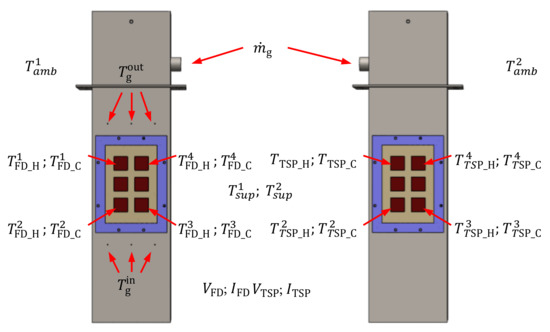
Figure 11.
Sensors and probes distribution along the thermoelectric generators.

Table 1.
Resolution and accuracy of the measurement probes.
Once the prototype has been completely designed and built it is installed at the exhaust duct of the boiler’s combustion chamber. Then, the connections of the probes and sensors are made and a trial experiment is performed to check the performance of the whole system and determine the limit working conditions. Thanks to this test, the maximum inlet temperature of the hot gases in the thermoelectric generator is set to 405 so as not to exceed the 230 on the hot face of the thermoelectric modules, as recommended by the manufacturer.
4. Results and Discussion
The main goal of this study is to prove the performance of a whole thermoelectric generator under real working conditions and maximise the electric power output obtained. Both systems, TEG_FD and TEG_TSP, are compared and the behaviour of these devices is analysed for different input parameters. Firstly, the influence of the load resistance is studied obtaining the performance curve of the generators. It has also been explored the effect of the auxiliary consumption that, in this case, has the fan employed with the finned dissipater, which punishes the total power output. And finally, the influence of the mass flow of the hot gases has been investigated trying to obtain the maximum electric power from the generators. The methodology described in Section 2 is employed for the discussion of the results.
4.1. Influence of the Load Resistance
Setting an inlet temperature, , of 405 and a mass flow of 70 / the performance of both thermoelectric generators have been tested varying the load resistance connected to the thermoelectric modules. The feed voltage to the fan of the finned heat sink of the TEG_FD is set to 4 . Figure 12 show the results and, as expected, the power output grows along with the load resistance up to a maximum point in this case in the range from 19–22. Beyond this point, the power generation starts to slowly decrease.

Figure 12.
Net power output of both thermoelectric generators as a function of the load resistance.
In all cases, the power output generated by the TEG_TSP is higher than the electricity produced by the TEG_FD. With the TEG_TSP are generated, which represents per thermoelectric module, whereas, with the TEG_FD, the total power output is from which must be taken out due to the auxiliary consumption of the fan. Therefore, a net power output of are produced, which is per thermoelectric module; that represents a 54.4% lower than the other generator. As shown in Table 2, this difference is achieved thanks to the lower thermal resistances of the thermosyphon, / per module; compared to the thermal resistance of the finned dissipater, /. Thus, more thermal power goes through the TEG_TSP, getting a higher temperature difference between the faces of the modules, and therefore, producing more electric power.
Table 2.
Experimental results of the thermoelectric generators for an inlet temperature of , a mass flow of , and a voltage of the fan of 4 .
4.2. Influence of the Auxiliary Consumption
The second aspect that wanted to be tested is the auxiliary consumption necessary of the fan that moves the air through the finned dissipater in one of the thermoelectric generators. The higher the velocity of the air, the lower the thermal resistance of that heat exchanger, which leads to a higher temperature difference between the faces of the modules and higher power output. However, it also increases the extra consumption of the auxiliary system, decreasing the net power output at a certain level. Setting the load resistance to its optimal value, obtained from the previous analysis, and an inlet temperature of the gases at 405 with a mass flow of 70 /, the results of Figure 13 and Table 3 are obtained. For the TEG_FD prototype, shifting from 4 to 8 for the voltage supplied to the fan causes a reduction of the thermal resistance of the finned dissipater from / to /, which increases the total electric production from to . This effect is achieved with an increment of the auxiliary consumption from to . Here, the rise of the total power output is higher than the increase of the auxiliary consumption, therefore the net electric generation also rises from to . However, at a voltage of 12 for the fan, the rise of the power generation is lower than the increment in the auxiliary consumption. That is why the net electric production decreases. As a consequence, an optimum value for the net power generation is obtained at a fan voltage of 8 .

Figure 13.
Influence of the auxiliary consumption on the net power output of the thermoelectric generators.
Table 3.
Experimental results of the thermoelectric generators for an inlet temperature of , a mass flow of , and several voltages applied to the fan of the TEG_FD.
In any case, the electric output of the TEG_TSP is , a 63.7% higher than the electric production of the TEG_FD, even at the maximum generation point which is , at a voltage of the fan of 8 .
4.3. Influence of the Hot Gases Mass Flow
Finally, the influence of the mass flow of the gases that goes through the pipe is studied. For that, a constant inlet temperature of them is set to 405 and a voltage of 8 , that maximises the net power output, is used for the fan of the TEG_FD.
In both prototypes, whose results are shown in Figure 14 and Table 4 the net power output increases as the mass flow of the gases is risen from 70 / to 130 /. In the TEG_TSP the electric output goes from to at the optimum load resistance value, which is an improvement of a 12.8%. Considering the TEG_FD the electric output goes from 6 to at the optimum load resistance value again, which represents an improvement of a 15%. The reason for that is the reduction of the thermal resistance at the hot side of the generator, due to the rise of the mass flow, and the enhancement of the heat transfer leading to higher temperature differences between the faces of the modules.

Figure 14.
Influence of the auxiliary consumption on the net power output of the thermoelectric generators.
Table 4.
Experimental results of the thermoelectric generators for an inlet temperature of , different mass flow rates, and a voltage applied to the fan of the TEG_FD of 8 .
5. Conclusions
In this work, the design, optimization and experimentation of a complete thermoelectric generator for waste heat recovery have been performed. A study methodology has been developed to understand the performance of the whole system including the analysis of the heat fluxes and thermal resistances. The heat exchangers at both sides of the thermoelectric modules have been considered and designed. The hot side heat exchanger has been optimized using the computational fluid dynamics software, ANSYS Fluent. The finned dissipater employed in this part has been studied for different geometries and arrangements considering not only the thermal behaviour but also its effect on the hot gases current, by studying the pressure losses inside the duct. After the simulations, a geometry with low thermal resistance has been selected and built.
For the cold side heat exchanger, two options have been studied. The first one is the use of a finned dissipater with a fan; the other is a biphasic thermosyphon that works under free convection, acting as a passive heat exchanger. The idea was to compare both alternatives working on the same conditions.
After the experimental tests, the power generation curve for both thermoelectric generators has been obtained as a function of the load resistance to which the thermoelectric modules are connected. The device that uses the biphasic thermosyphon produces up to ; which represents a 82.8% more electric output than the other generator that uses a finned dissipater, .
The influence of the auxiliary consumption on the net power output has been also analysed for the thermoelectric generator with the finned dissipater, increasing its production up to with a voltage of 8 supplied to the fan of this dissipater.
Finally, the effect of the mass flow of the hot gases has also been studied. As expected, the higher the mass flow, the higher heat transfer coefficients inside the duct, which causes an increase on the temperature difference between the module’s faces and thus an increment on the power output. The maximum electric power generation is achieved for an inlet temperature of the gases at 405 and a mass flow of 130 /, reaching in the thermoelectric generator with the biphasic thermosyphon and in the generator with the finned dissipater.
This work has remarked the importance of optimizing hot and cold side heat exchangers when designing a thermoelectric generator. It is vital to take into account not only the thermal performance of such devices but also their influence over the entire generator: pressure losses, compactness, etc. It has also been proven that the extra consumption of the auxiliary equipment must always be considered to estimate the net power output of a thermoelectric generator. Besides, the use of a passive heat exchanger, through a biphasic thermosyphon under free convection, has resulted to be of great interest in this application.
Author Contributions
Conceptualization, D.A. and P.A.; methodology, M.A. and Á.C.; validation, L.C.; investigation, M.A.; resources, D.A.; writing—original draft preparation, M.A.; writing—review and editing, P.A. and Á.C.; funding acquisition, D.A. All authors have read and agreed to the published version of the manuscript.
Funding
This research was funded by the Spanish Ministry of Science, Innovation and Universities, and European Regional Development Fund research project number RTI2018-093501-B-C22; and the Education Department of the Government of Navarra with the Predoctoral Grants for Phd programms of Interest to Navarra.
Institutional Review Board Statement
Not applicable.
Informed Consent Statement
Not applicable.
Data Availability Statement
Not applicable.
Conflicts of Interest
The authors declare no conflict of interest. The funders had no role in the design of the study; in the collection, analyses, or interpretation of data; in the writing of the manuscript, or in the decision to publish the results.
Abbreviations
The following abbreviations are used in this manuscript:
| Pressure losses, | |
| FD | Finned dissipater |
| I | Electric current, |
| mass flow of the gases, | |
| heat power released at the cold side of the generator, | |
| heat power absorbed at the hot side of the generator, | |
| waste heat absorbed from the gases, | |
| Pressure at the inlet, | |
| Pressure at the outlet, | |
| Thermal resistance of the cold heat exchanger, | |
| Thermal resistance of the hot heat exchanger, | |
| Temperature at the cold side of the generator, | |
| Temperature at the hot side of the generator, | |
| Inlet temperature of the gases, | |
| Outlet temperature of the gases, | |
| TEG | Thermoelectric Generator |
| TSP | Thermosyphon |
| V | Electric voltage, |
| electric power output, |
References
- Jiménez-Arreola, M.; Pili, R.; Dal Magro, F.; Wieland, C.; Rajoo, S.; Romagnoli, A. Thermal power fluctuations in waste heat to power systems: An overview on the challenges and current solutions. Appl. Therm. Eng. 2018, 134, 576–584. [Google Scholar] [CrossRef]
- Sun, L.; Wang, D.; Xie, Y. Energy, exergy and exergoeconomic analysis of two supercritical CO2 cycles for waste heat recovery of gas turbine. Appl. Therm. Eng. 2021, 196, 117337. [Google Scholar] [CrossRef]
- Kim, Y.M.; Negash, A.; Mehdi Shamsi, S.S.; Shin, D.G.; Cho, G. Experimental Study of a Lab-Scale Organic Rankine Cycle Sytem for Heat and Water Recovery from Flue Gas in Thermal Power Plants. Energies 2021, 14, 4328. [Google Scholar] [CrossRef]
- Oyelami, A.T.; Adejuyigbe, S.B.; Olusunle, S.O. Thermal analysis of recuperator developed for waste heat recycling in liquid-fuel fired furnaces. Int. J. Heat Technol. 2021, 39, 121–127. [Google Scholar] [CrossRef]
- Meng, F.; Chen, L.; Feng, Y.; Xiong, B. Thermoelectric generator for industrial gas phase waste heat recovery. Energy 2017, 135, 83–90. [Google Scholar] [CrossRef]
- Yazawa, K.; Shakouri, A.; Hendricks, T.J. Thermoelectric heat recovery from glass melt processes. Energy 2017, 118, 1035–1043. [Google Scholar] [CrossRef]
- Araiz, M.; Casi, Á.; Catalán, L.; Martínez, Á.; Astrain, D. Prospects of waste-heat recovery from a real industry using thermoelectric generators: Economic and power output analysis. Energy Convers. Manag. 2020, 205, 112376. [Google Scholar] [CrossRef]
- Nesarajah, M.; Frey, G. Optimized Design of Thermoelectric Energy Harvesting Systems for Waste Heat Recovery from Exhaust Pipes. Appl. Sci. 2017, 7, 634. [Google Scholar] [CrossRef] [Green Version]
- Chiarotti, U.; Moroli, V.; Menchetti, F.; Piancaldini, R.; Bianco, L.; Viotto, A.; Baracchini, G.; Gaspardo, D.; Nazzi, F.; Curti, M.; et al. Development of a Small Thermoelectric Generators Prototype for Energy Harvesting from Low Temperature Waste Heat at Industrial Plant. J. Nanosci. Nanotechnol. 2017, 17, 1586–1591. [Google Scholar] [CrossRef] [PubMed]
- Børset, M.T.; Wilhelmsen, Ø.; Kjelstrup, S.; Burheim, O.S. Exploring the potential for waste heat recovery during metal casting with thermoelectric generators: On-site experiments and mathematical modeling. Energy 2017, 118, 865–875. [Google Scholar] [CrossRef] [Green Version]
- Astrain, D.; Aranguren, P.; Martínez, A.; Rodríguez, A.; Pérez, M.G. A comparative study of different heat exchange systems in a thermoelectric refrigerator and their influence on the efficiency. Appl. Therm. Eng. 2016, 103, 1289–1298. [Google Scholar] [CrossRef]
- Hatami, M.; Ganji, D.D.; Gorji-Bandpy, M. A review of different heat exchangers designs for increasing the diesel exhaust waste heat recovery. Renew. Sustain. Energy Rev. 2014, 37, 168–181. [Google Scholar] [CrossRef]
- Mostafavi, S.A.; Mahmoudi, M. Modeling and fabricating a prototype of a thermoelectric generator system of heat energy recovery from hot exhaust gases and evaluating the effects of important system parameters. Appl. Therm. Eng. 2018, 132, 624–636. [Google Scholar] [CrossRef]
- Yu, R.; Chaoyi, W.; Shusheng, Z. Transitional Flow and Heat Transfer Characteristics in a Rectangular Duct with Stagger-arrayed Short Pin Fins. Chin. J. Aeronaut. 2009, 22, 237–242. [Google Scholar] [CrossRef] [Green Version]
- Zhao, C.Y.; Lu, W.; Tassou, S.A. Thermal analysis on metal-foam filled heat exchangers. Part II: Tube heat exchangers. Int. J. Heat Mass Transf. 2006, 49, 2762–2770. [Google Scholar] [CrossRef]
- Ejlali, A.; Ejlali, A.; Hooman, K.; Gurgenci, H. Application of high porosity metal foams as air-cooled heat exchangers to high heat load removal systems. Int. Commun. Heat Mass Transf. 2009, 36, 674–679. [Google Scholar] [CrossRef] [Green Version]
- Wang, T.; Luan, W.; Liu, T.; Tu, S.T.; Yan, J. Performance enhancement of thermoelectric waste heat recovery system by using metal foam inserts. Energy Convers. Manag. 2016, 124, 13–19. [Google Scholar] [CrossRef]
- Chen, J.; Zuo, L.; Wu, Y.; Klein, J. Modeling, experiments and optimization of an on-pipe thermoelectric generator. Energy Convers. Manag. 2016, 122, 298–309. [Google Scholar] [CrossRef] [Green Version]
- Remeli, M.F.; Date, A.; Orr, B.; Ding, L.C.; Singh, B.; Affandi, N.D.N.; Akbarzadeh, A. Experimental investigation of combined heat recovery and power generation using a heat pipe assisted thermoelectric generator system. Energy Convers. Manag. 2016, 111, 147–157. [Google Scholar] [CrossRef]
- Martínez, A.; Astrain, D.; Aranguren, P. Thermoelectric self-cooling for power electronics: Increasing the cooling power. Energy 2016, 112, 1–7. [Google Scholar] [CrossRef] [Green Version]
- Tzeng, S.C.; Jeng, T.M.; Lin, Y.L. Parametric study of heat-transfer design on the thermoelectric generator system. Int. Commun. Heat Mass Transf. 2014, 52, 97–105. [Google Scholar] [CrossRef]
- Kim, T.Y.; Negash, A.A.; Cho, G. Waste heat recovery of a diesel engine using a thermoelectric generator equipped with customized thermoelectric modules. Energy Convers. Manag. 2016, 124, 280–286. [Google Scholar] [CrossRef]
- Shabgard, H.; Allen, M.J.; Sharifi, N.; Benn, S.P.; Faghri, A.; Bergman, T.L. Heat pipe heat exchangers and heat sinks: Opportunities, challenges, applications, analysis, and state of the art. Int. J. Heat Mass Transf. 2015, 89, 138–158. [Google Scholar] [CrossRef]
- Aranguren, P.; Astrain, D.; Martínez, A. Study of complete thermoelectric generator behavior including water-to-ambient heat dissipation on the cold side. J. Electron. Mater. 2014, 43, 2320–2330. [Google Scholar] [CrossRef] [Green Version]
- Date, A.; Date, A.; Dixon, C.; Singh, R.; Akbarzadeh, A. Theoretical and experimental estimation of limiting input heat flux for thermoelectric power generators with passive cooling. Sol. Energy 2015, 111, 201–217. [Google Scholar] [CrossRef]
- Remeli, M.F.; Tan, L.; Date, A.; Singh, B.; Akbarzadeh, A. Simultaneous power generation and heat recovery using a heat pipe assisted thermoelectric generator system. Energy Convers. Manag. 2015, 91, 110–119. [Google Scholar] [CrossRef]
- Araiz, M.; Martínez, A.; Astrain, D.; Aranguren, P. Experimental and computational study on thermoelectric generators using thermosyphons with phase change as heat exchangers. Energy Convers. Manag. 2017, 137, 155–164. [Google Scholar] [CrossRef] [Green Version]
- Quirepace. YP3 Blower; Technical Report; Quirepace: Fareham, UK, 2017. [Google Scholar]
- Aranguren, P.; Araiz, M.; Astrain, D.; Martínez, A. Thermoelectric generators for waste heat harvesting: A computational and experimental approach. Energy Convers. Manag. 2017, 148, 680–691. [Google Scholar] [CrossRef] [Green Version]
- Astrain, D.; Vian, J. Study and Optimization of the Heat Dissipater of a Thermoelectric Refrigerator. J. Enhanc. Heat Transf. 2005, 12, 159–170. [Google Scholar] [CrossRef]
Publisher’s Note: MDPI stays neutral with regard to jurisdictional claims in published maps and institutional affiliations. |
© 2021 by the authors. Licensee MDPI, Basel, Switzerland. This article is an open access article distributed under the terms and conditions of the Creative Commons Attribution (CC BY) license (https://creativecommons.org/licenses/by/4.0/).