Abstract
The droop control scheme based on Q − ω and P − V characteristics is conventionally employed to share the load power among sources in an islanded low-voltage microgrid with resistive line impedances. However, it suffers from poor active power sharing, and is vulnerable to sustained deviations in frequency and voltage. Therefore, accurate power sharing and maintaining the frequency and voltage in the desired ranges are challenging. This paper proposes a novel microgrid control strategy to address these issues. The proposed strategy consists of a virtual flux droop and a model predictive control, in which the virtual flux is the time integral of the voltage. Firstly, the novel virtual flux droop control is proposed to accurately control the power sharing among DGs. Then, the model predictive flux control is employed to generate the appropriate switching signals. The proposed strategy is simple without needing multiple feedback control loops. In addition, pulse width modulation is not required and tuning challenges for PI regulators are avoided. In order to evaluate the effectiveness of the proposed microgrid control strategy, simulation analysis is carried out in Matlab/Simulink software environment. The results show that accurate power sharing is achieved while a good dynamic response is provided. Furthermore, the voltage and frequency deviations are significantly improved.
1. Introduction
In recent decades, many efforts have been made to increase the penetration of distributed generators (DGs) based on renewable resources such as PV and wind turbines in distribution networks [1,2]. The concept of microgrid has emerged as a promising approach to integrate different types of DGs into the existing AC power grids. In particular, reliable stand-alone DGs are very useful and promising for providing energy resilience strategies for remote communities, i.e. DGs with proper control schemes can help to provide a reliable and regular supply of energy and keep essential operations running when the grid goes down. DGs are commonly interfaced to an islanded microgrid by inverters in parallel [2,3,4,5,6,7]. This structure brings the advantages of flexibility, high redundancy and is economic [8,9].
In the islanded microgrid, the connection to the main grid is not available. In this condition, the microgrid operates autonomously. Therefore, an appropriate control strategy should be applied to accurately share the load among DGs as well as maintaining frequency and voltage level within the permissible ranges. The conventional droop method is widely used for controlling islanded microgrids. The main advantage of this method is that there is no dependency on the communication links which allows the “plug and play” functionality of DGs [9,10,11,12]. In the islanded microgrid with inverter based-DGs, the conventional droop method can adjust frequency and amplitude of the inverter voltage by adjusting active and reactive powers delivered to the microgrid, respectively. However, it has the disadvantage of frequency and voltage deviations and poor power sharing [13]. Moreover, the conventional droop method is based on an assumption that line impedances are inductive, while they are mainly resistive in low-voltage microgrids. As a result, the power sharing accuracy is further reduced [14].
In order to solve problems of the conventional droop method for power sharing of an islanded low-voltage microgrid with parallel inverters, some improved droop control strategies have been proposed in the literature. Researchers have attempted to modify the relations between the parameters in the conventional droop. In this regard, it was proposed to use and for low-voltage microgrids, with highly resistive line impedances. Although this control method offers improved performance, it cannot properly share the active power [15,16]. A strategy was proposed in [10]. However, the power sharing accuracy of this kind of control method is affected by the improper operation of the restoration mechanism to bring to zero at steady-state. An improved method based on was proposed to address this issue. However, it is not effective for islanded microgrids with resistive line impedances. In [12] a strategy was adopted to improve the active power sharing and voltage control. However, avoiding large oscillations in this scheme relies on an extra control gain which needs much effort to be carefully designed.
Injecting modifying signals has been taken into account as another approach to improve the power sharing control. For this reason, in [17] an amended control method based on the conventional and droop was proposed so that a small real power disturbance is injected to estimate the reactive power control error. Moreover, in [18] an enhanced method using AC bus signaling was proposed to improve the accuracy of the reactive power sharing, which needs the estimation of the line resistance. However, the effectiveness of these control strategies depends on the accuracy of the estimation process, which is difficult in practice. In addition, the quality of the output current and voltage may be affected by injecting AC signals to the output voltage reference in these control methods.
The third approach to achieve accurate power sharing is based on the virtual impedance technique which can be employed in the low-voltage microgrid, where the line impedances are highly resistive. The line impedances can be reshaped to be purely inductive or resistive by incorporating virtual impedance. In this regard, an improved method was proposed in [19,20]. However, the value determination of the virtual impedances in different conditions is difficult. Furthermore, the initial value of output impedances should be accurately acquired to completely compensate for the errors of line impedances, which is difficult in practice.
Regarding the aforementioned methods, it should be noted that the control structures usually consist of the inner current loop and the outer voltage loop. Subsequently, complex coordinate transformations and careful tuning of PI regulators are needed. In addition, using the concept of virtual impedance or injecting auxiliary signals to overcome the disadvantages of the conventional droop method leads to multiple feedback signals, where additional regulators have to be used. Moreover, sinusoidal pulse width modulation is needed to generate the switching signals [21,22,23,24,25]. All these factors make applications of these controllers limited in practice.
The idea of virtual flux droop control is taken into account as an effective strategy to deal with these problems. Based on this idea, the virtual flux, which is the time integral of the voltage, is expressed as a function of the reactive power. In addition, the angular difference between the virtual fluxes is expressed as a function of active power. In this method, there is no need for complex transformations and tuning of PI regulators. Moreover, the switching signals are generated by the direct flux control technique in a similar way to direct torque control and direct power control methods. Two hysteresis comparators are employed to produce the inputs of a look-up table, and subsequently, the proper switching vector is selected [26,27,28]. However, this control strategy is developed for an islanded microgrid with highly inductive line impedances. Therefore, it cannot accurately share the load demand between sources in the case that the line impedances are highly resistive. Moreover, the ripples of voltage and current are inevitable due to the hysteresis comparators [4,29].
This paper proposes a novel microgrid control strategy to overcome the aforementioned problems in the low-voltage islanded microgrids with resistive line impedances. Firstly, a novel virtual flux droop control (NVFD) is proposed assuming that line impedances are highly resistive. Then, a model predictive flux control (MPFC) is developed to appropriately select the optimal switching vector. The idea of the model predictive control (MPC) for power electronic converters offers several advantages; for example, this idea is simple and provides a fast dynamic response, moreover, it is possible to incorporate nonlinearities and constraints of the system and variables into the model. Therefore, MPFC is taken into account as the effective solution to improve the control strategy of the microgrid. The MPFC uses a model for predicting the future behavior of the variables to be controlled. Subsequently, all possible switching states are evaluated by a cost function that formulates the desired behavior of the system. Consequently, the appropriate switching signals are obtained, and are applied to the inverter. The merits of the proposed control strategy in this article are:
- (1)
- It is straightforward, as there is no need for multiple feedback control loops.
- (2)
- It can share the demanded load power between DGs proportional to their ratings.
- (3)
- It can deal with the problem of deviations in voltage and frequency. Moreover, the voltage and current waveforms meet the IEEE Std 519-2014 [30] and the frequency waveform meets the international standard CENELEC EN50160 [31].
- (4)
- The expandability and the high reliability of the islanded microgrid are maintained.
The remaining sections of this paper are organized as follows: Section 2 describes the mathematical equations of the proposed virtual flux droop control for the islanded microgrid with highly resistive line impedances. Then the microgrid control strategy based on the NVFD and the MPFC is proposed in Section 3. The effectiveness of the proposed control strategy is validated by simulation analysis in the Matlab/Simulink software environment. In addition, the results are evaluated by comparing with the conventional droop control scheme based on the voltage active power droop and frequency reactive power boost (VPD/FQB) method with and characteristics in Section 4. Finally, this paper is summarized in Section 5.
2. Proposed Virtual Flux Droop Control
The equivalent circuit of an islanded microgrid is shown in Figure 1. The parallel inverters interfacing DGs to the microgrid are connected to the common bus through the line impedances. The mathematical equation of this circuit is obtained by Kirchhoff’s voltage law:
where is the output voltage vector of the inverter, is the voltage vector of the common bus, and is the injected current vector to the common bus. In addition, and are respectively the resistance and the inductance of the line impedance. Moreover, the number of the inverter is denoted by the subscript “i”.
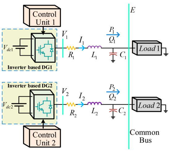
Figure 1.
An islanded microgrid with parallel inverters.
The delivered power to the common bus by the inverter is calculated by:
where is the complex power. Furthermore, and are respectively the active and the reactive powers.
Similar to the magnetic flux in electrical machines, the virtual flux vectors are defined as the time integral of the corresponding voltage vectors by:
where and are respectively the virtual flux vectors of the inverter “i” and the common bus which have the angles represented by and . Therefore, amplitudes and phase angles of the virtual fluxes can be achieved in terms of amplitudes and phase angles of the corresponding voltage vectors:
where and are the angles of the and , respectively. In addition, is the angular frequency.
Assuming that the line impedances are highly resistive, the injected current is obtained in terms of virtual fluxes by neglecting the line inductance and using Equations (1), (3) and (4):
Now, the delivered complex power is rewritten in terms of virtual fluxes by substituting Equations (4)–(7) in Equation (2):
Equation (8) is decomposed to the real and imaginary parts which are respectively equal to the active and reactive powers. Therefore:
where is the angular difference in radians defined as [26]. The angular difference between the voltages of the inverter and the common bus is typically small, which results in:
Consequently:
The aforementioned analysis indicates that the active power is associated with the amplitude difference between the virtual fluxes, i.e., and similarly, the reactive power is related to the angular difference. As a result, the mathematical equations of the novel virtual flux droop control are proposed as follows:
where is the nominal active power, is the nominal reactive power, and are the droop coefficients, is the nominal angular difference and is the nominal virtual flux amplitude of the inverter. The control commands and determine values of the angular difference and the virtual flux amplitude of the inverter.
3. Proposed Microgrid Control Strategy
The MPC method is considered as an effective control method for power electronic converters. The idea of MPC is simple and easy to understand. Moreover, it is possible to easily incorporate the constraints and the nonlinearities of the system. The desired behavior of the MPC is guided through the formulation of a cost function to be minimized [32,33,34]. Thus, the MPC method is employed in this paper to propose the control strategy for the islanded microgrid consisting of parallel inverter-based DGs.
The structure of the proposed control strategy for the islanded microgrid is shown in Figure 2. It is composed of power sharing control, inverter model, prediction mechanism and cost function minimization described in the following section.
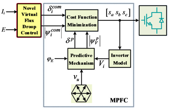
Figure 2.
Structure of the proposed microgrid control strategy.
3.1. Power Sharing Control
The power demanded by the load should be shared proportionally to the ratings of the inverters while the voltage and the frequency are maintained within the desired ranges. This problem has been addressed in the literature by using different control methods, for example [35], has redesigned a conventional and droop controller based on a total sliding-mode control (TSMC) technique. In the proposed method in this article, an accurate power sharing is achieved by the novel virtual flux droop control. As described in Section 2, the delivered active power and the delivered reactive power are calculated and subsequently, the command values are obtained for the virtual flux amplitude of the inverter and the angular difference using Equations (15) and (16).
3.2. Inverter Model
Considering that two-level inverters are used in this paper, there are 8 possible switching states, which can be represented by:
where is the switching state vector. In addition, , and are three binary switching signals corresponding to phase a, phase b and phase c of the inverter, respectively. The status of each switch is given by ; if the corresponding switch is off and if the corresponding switch is on. The switching state vector can be expressed in the frame by:
where is the switching state vector in the frame and . The switching state vectors are shown in Figure 3. The corresponding voltage space vectors generated by the inverter in the frame are also illustrated, which can be obtained in terms of the switching state vectors by:
is the voltage space vector in the frame, and are respectively the real and the imaginary parts of in the frame, and is the input dc voltage of the inverter. The complex forms of voltage space vectors in the frame are given in Table 1. Note that , which leads to only seven different voltage space vectors.
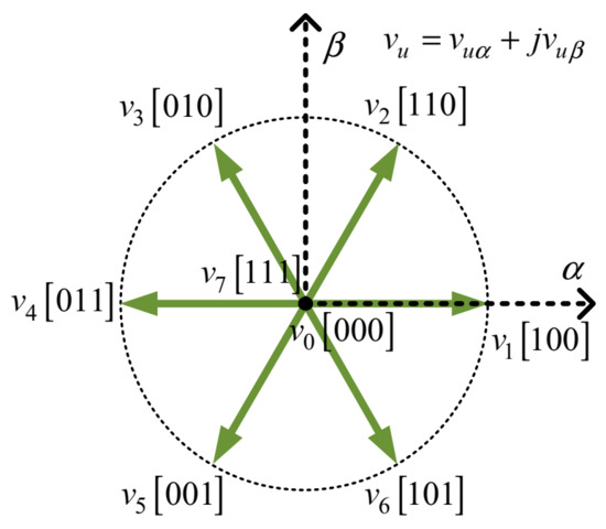
Figure 3.
Possible voltage space vectors in the frame.

Table 1.
Possible switching states and related voltage space vectors used in two-level three-phase inverter.
3.3. Prediction Mechanism
The output voltage and the virtual flux of the inverter at sampling instant in the complex frame are achieved using Equations (3) and (19). The virtual flux amplitude of the inverter and the angular difference between the inverter and the common bus virtual flux vectors have to be predicted. The components of the inverter virtual flux in the frame i.e., and are expressed using Equation (3):
where is the sampling period. Subsequently, the amplitude and the phase angle of the inverter virtual flux at the next sampling instant are obtained by:
The superscript “p” denotes the predicted variables. It should be noted that the phase angle of the virtual flux of the common bus is generated using a virtual three-phase voltage. Then, it is achieved at the next sampling instant by:
Therefore, the angular difference between the virtual flux vectors of the inverter and the common bus is predicted at the next sampling instant by:
3.4. Cost Function Minimization
In order to select the optimal switching state vector, the predicted values of and are evaluated by the cost function for all seven voltage space vectors. Therefore, the optimal , which minimizes the cost function, is selected and the related switching state vector will be applied to the inverter at the next sampling instant. The cost function represents the desired behavior of the system. In this paper, the cost function is defined in such a way that both the virtual flux amplitude of the inverter and the angular difference between the virtual fluxes of the inverter and the common bus are close to their command values. The related command values are calculated based on the NVFD using Equations (15) and (16). Thus, the cost function is expressed by:
where and are the weighting factors. By reducing the cost function, the first term aims to decrease the virtual flux ripples, and the second term aims for a reduction in the angular difference ripples. Therefore, the weighting factors are tuned by considering a trade-off between the ripples’ reduction in the virtual flux amplitude and the angular difference.
4. Simulation Results Analysis
The effectiveness of the proposed control strategy is evaluated using the simulation analysis in Matlab/Simulink software environment. In this regard, the islanded microgrid for which the line impedances are highly resistive is simulated and the proposed control strategy is applied. The inverter based-DGs are connected to each other through a tie-line, as shown in Figure 4. For a small remote community it is desirable to have DGs close to each other, which leads to low voltage drop and easy communication, however for some reasons, the DGs may be far apart. In this condition, good DGs parallel operation will be achieved by connecting the inverters through tie-lines. Therefore, the tie-line connection has been considered in this paper for more accurate analysis. In addition, the inductances of the line and the filter are modeled together as [26,28].
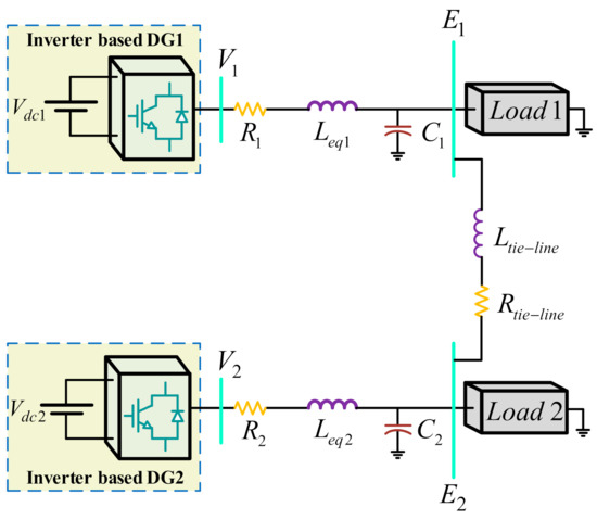
Figure 4.
Parallel operation of the islanded microgrid under study via a tie-line connection.
In studying the system, an event is created in which the load demand suddenly decreases at t = 2 s and then it increases to the initial value at t = 4 s. The parameters of the microgrid and the controller are listed in Table 2. The performance of the proposed control strategy is compared with the VPD/FQB method [16], which is based on and characteristics, for the highly resistive microgrids. The comparison results are presented in Table 3. The droop characteristics of the VPD/FQB method are described by the following mathematical equations:
where and are the angular frequency and the output voltage amplitude of the inverter at no load, respectively. Moreover, and are the injected active power and the injected reactive power, respectively. In addition, and are the command values for the angular frequency and the output voltage amplitude of the inverter. Furthermore, and are the droop coefficients. The subscript “i” denotes the number of the inverter.
Table 2.
Microgrid and control parameters.
Table 3.
Comparison results in steady-state for the nominal condition.
The load-side voltage waveforms of DG1 for the conventional method and the proposed control strategy are shown in Figure 5 and Figure 6, respectively. Subsequently, their THD spectra in the nominal condition are illustrated in Figure 7 and Figure 8, respectively. Furthermore, the per-unit values of the line voltages for the conventional method and the proposed strategy are compared as shown in Figure 9. Although the voltage waveforms are balanced and quite sinusoidal for both control schemes, the amplitude of the voltage deviations for the proposed control strategy is considerably lower than the conventional method as given in Table 3, which also leads to an improvement in the THD index. Decreasing the load at t = 2 s typically leads to an increase in the per-unit value of the load-side voltage. However, the conventional control method cannot keep the voltage within the permissible range, while the proposed control strategy can maintain the voltage within the desired range (), and therefore, its effectiveness in the voltage control is validated.
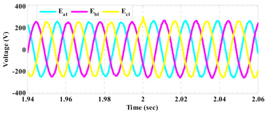
Figure 5.
Load-side voltage waveforms of DG1 based on the conventional control method.
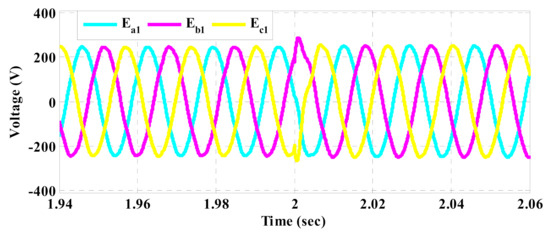
Figure 6.
Load-side voltage waveforms of DG1 based on the proposed control strategy.
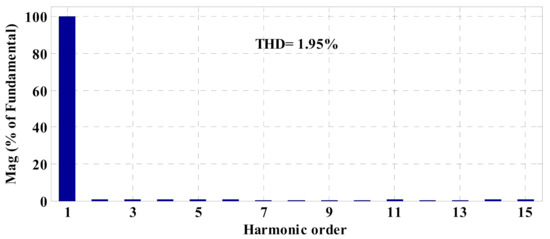
Figure 7.
THD spectra of load-side voltage of DG1 based on the conventional control method.

Figure 8.
THD spectra of load-side voltage of DG1 based on the proposed control strategy.
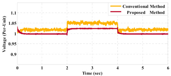
Figure 9.
Line voltage comparison of the load-side voltage of DG1.
The current waveforms injected by DG1 based on the conventional and the proposed schemes are respectively shown in Figure 10 and Figure 11. In addition, their THD spectra are depicted in Figure 12 and Figure 13, respectively. Furthermore, the injected currents of DGs in the nominal condition, based on the conventional method and the proposed strategy are also shown in Figure 14 and Figure 15, respectively. As can be seen, the load demand is improperly shared among DGs in the conventional method because the injected currents of DGs are almost equal despite being different in rating. On the other hand, the injected currents of DGs based on the proposed control strategy are proportional to their ratings. The effectiveness of the conventional method depends on the performance of the inner current control loop, where PI regulators are employed. However, PI regulators and also the inner current control loop are omitted in the structure of the proposed control strategy and the best switching vector is chosen using the model predictive flux control scheme. Thus, the performance of the proposed strategy is overall improved in different conditions of the load demand, which leads to better current control. As a result, the THD index of the current is reduced in comparison to the conventional method, as given in Table 3.
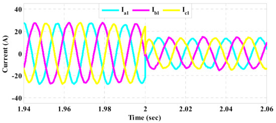
Figure 10.
Injected current waveforms of DG1 based on the conventional control method.
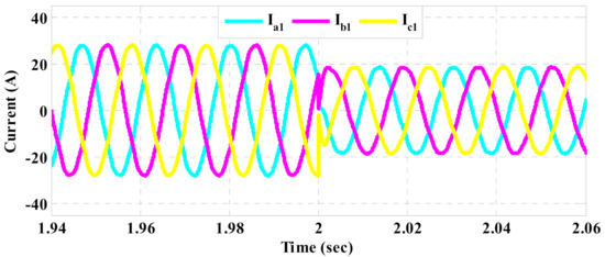
Figure 11.
Injected current waveforms of DG1 based on the proposed control strategy.
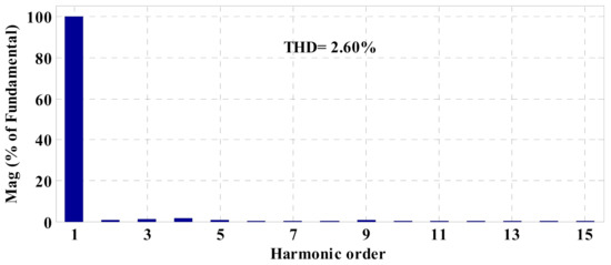
Figure 12.
THD spectra of the injected current of DG1 based on the conventional control method.
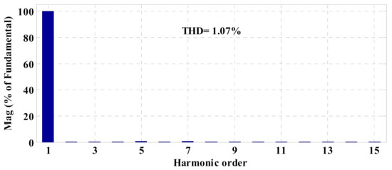
Figure 13.
THD spectra of the injected current of DG1 based on the proposed control strategy.
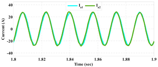
Figure 14.
Injected currents of DGs to the microgrid based on the conventional control method.
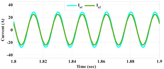
Figure 15.
Injected currents of DGs to the microgrid based on the proposed control strategy.
The delivered active and reactive powers of both DGs to the microgrid for the conventional method and the proposed control strategy are shown in Figure 16 and Figure 17, respectively. To compare the results, the errors for active and reactive powers in the nominal condition are defined as:
where and are respectively the active power and the reactive power errors, In addition, and are respectively the actual active and reactive powers. Furthermore, and are the rated values of the active and reactive powers of DGi. N is the number of total DGs, which in this paper is equal to two. The load demand is improperly shared among DGs due to the poor performance of the conventional method in power sharing. Therefore, the power share of each DG is not proportional to its rating. Nevertheless, the proposed control strategy can accurately share the load demand in different conditions among DGs proportional to their ratings. As a result, the power errors (especially the active power errors) are reduced in comparison to the conventional method, as given in Table 3.
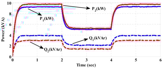
Figure 16.
Delivered power to the microgrid based on the conventional control method.
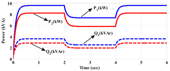
Figure 17.
Delivered power to the microgrid based on the proposed control strategy.
Figure 18 shows the comparison of the frequency response for both control schemes. The poor frequency control of the conventional VPD/FQB control method based on control loop leads to the frequency deviation. However, because of the tight control of the angular difference between the virtual flux vectors of the inverter and the common bus in the proposed method, both virtual flux vectors will rotate with a fixed angular frequency. As a result, regardless of how much δ has changed, the angular frequency of the virtual flux vector of the common bus will be constant. Regarding Figure 18, the dynamic frequency response of the proposed strategy is very fast and its transient response is sufficiently damped. Therefore, the frequency response based on the proposed strategy reaches the steady-state sooner. In the steady-state condition, the frequency error is quite near zero and the frequency deviations are negligible. On the contrary, the steady-state frequency deviations of the conventional method, i.e., VBD/FQB method, are larger and persistent. In addition, after the load changes from a nominal value, the frequency error is significant in the steady-state in the VBD/FQB method. However, there is a drawback in the proposed method. The maximum frequency deviation in the transient state is more in the proposed strategy than in the conventional method. Nevertheless, it is still less than ±0.2 Hz (or about 0.34%) which is significantly less than the allowed variations range for frequency i.e., ±1% [18,31]. It should be noted that the control parameters in the proposed strategy can be tuned in such a way that the maximum frequency deviation is reduced. However, this leads to slower dynamic response. Therefore, the proposed strategy is superior in terms of its performance compared to the conventional method in frequency control.

Figure 18.
Frequency comparison of the islanded microgrid.
5. Conclusions
Studying the control schemes of islanded microgrids is very important for at least two reasons: (1) these microgrids may be designed as autonomous stand-alone microgrids, which have many applications. One application is to assist remote communities with having a reliable, resilient electrical energy service. (2) Grid-connected microgrids may occasionally switch to islanding mode either in a short period of time after a contingency, or for a longer time during natural disasters.
The control method for power sharing in the low-voltage islanded microgrid is conventionally based on and droop characteristics. However, it suffers from disadvantages such as poor active power sharing, and frequency and voltage deviations. This paper proposes a novel microgrid control strategy to overcome these problems in a low-voltage islanded microgrid with highly resistive line impedances. The proposed strategy consists of the novel virtual flux droop (NVFD) control and the model predictive flux control (MPFC). Firstly, the NVFD control produces the command values for the amplitude of the virtual flux vector of the inverter and its angular difference from the virtual flux vector of the common bus. Then, the MPFC uses the model of the system to predict the future behavior of the control parameters, i.e., the virtual flux amplitude of the inverter and its angular difference compared to the common bus. Subsequently, all possible voltage space vectors are evaluated using a defined cost function, and the optimal switching state vector is selected for applying to the inverter.
The proposed control strategy and the conventional control method are compared by simulation in the environment of Matlab/Simulink software. The results highlight that the proposed strategy offers more accurate power sharing and better voltage and frequency control in comparison to the conventional method. Therefore, the effectiveness of the proposed control strategy is confirmed.
Author Contributions
Conceptualization, methodology, software, and validation, S.K.; writing, S.K., M.B. and N.H.; writing—review, N.H., M.B. and F.B.; editing, N.H.; supervision, M.B., N.H., F.B. All authors have read and agreed to the published version of the manuscript.
Funding
This research received no external funding.
Institutional Review Board Statement
Not applicable.
Informed Consent Statement
Not applicable.
Data Availability Statement
No publicly archived dataset is used.
Conflicts of Interest
The authors declare no conflict of interest.
References
- Blaabjerg, F.; Yang, Y.; Ma, K.; Wang, X. Power electronics—The key technology for renewable energy system integration. In Proceedings of the 2015 International Conference on Renewable Energy Research and Applications (ICRERA), Palermo, Italy, 22–25 November 2015; pp. 1618–1626. [Google Scholar]
- Karimipouya, A.; Karimi, S.; Abdi, H. Microgrid frequency control using the virtual inertia and ANFIS-based Controller. Int. J. Ind. Electron. Control Optim. 2019, 2, 145–154. [Google Scholar]
- Chen, Y.; Guerrero, J.M.; Shuai, Z.; Chen, Z.; Zhou, L.; Luo, A. Fast reactive power sharing, circulating current and resonance suppression for parallel inverters using resistive-capacitive output impedance. IEEE Trans. Power Electron. 2016, 31, 5524–5537. [Google Scholar] [CrossRef] [Green Version]
- Khanabdal, S.; Banejad, M.; Blaabjerg, F.; Hosseinzadeh, N. Virtual Flux Droop Control with Constant Switching Frequency for Power Sharing Between Parallel Inverters in Islanded Microgrids. In Proceedings of the 2019 27th Iranian Conference on Electrical Engineering (ICEE), Yazd, Iran, 30 April–2 May 2019; pp. 868–874. [Google Scholar]
- Ghasemi, A.; Banejad, M.; Rahimiyan, M. Integrated energy scheduling under uncertainty in a micro energy grid. IET Gener. Transm. Distrib. 2018, 12, 2887–2896. [Google Scholar] [CrossRef]
- Jafarian, Y.; Karimi, A.; Bevrani, H. Secondary voltage control in a hybrid microgrid. Int. J. Ind. Electron. Control Optim. 2019, 2, 221–232. [Google Scholar]
- Sedaghati, R.; Shakarami, M. A new sliding mode-based power sharing control method for multiple energy sources in the microgrid under different conditions. Int. J. Ind. Electron. Control Optim. 2019, 2, 25–38. [Google Scholar]
- Zhang, Y.; Ma, H. Theoretical and Experimental Investigation of Networked Control for Parallel Operation of Inverters. IEEE Trans. Ind. Electron. 2011, 59, 1961–1970. [Google Scholar] [CrossRef]
- Chen, Z.; Pei, X.; Yang, M.; Peng, L. An Adaptive Virtual Resistor (AVR) Control Strategy for Low-Voltage Parallel Inverters. IEEE Trans. Power Electron. 2019, 34, 863–876. [Google Scholar] [CrossRef]
- Lee, C.; Chu, C.; Cheng, P. A new droop control method for the autonomous operation of distributed energy resource interface converters. IEEE Trans. Power Electron. 2013, 28, 1980–1993. [Google Scholar] [CrossRef]
- Zhong, Q.-C. Robust Droop Controller for Accurate Proportional Load Sharing among Inverters Operated in Parallel. IEEE Trans. Ind. Electron. 2013, 60, 1281–1290. [Google Scholar] [CrossRef]
- Chen, J.; Yue, D.; Dou, C.; Chen, L.; Weng, S.; Li, Y. A virtual complex impedance based droop method for paral-lel-connected inverters in low-voltage AC microgrids. IEEE Trans. Ind. Inform. 2021, 17, 1763–1773. [Google Scholar]
- Golsorkhi, M.S.; Shafiee, Q.; Lu, D.D.-C.; Guerrero, J.M. Distributed Control of Low-Voltage Resistive AC Microgrids. IEEE Trans. Energy Convers. 2018, 34, 573–584. [Google Scholar] [CrossRef]
- Bai, X.; Miao, H.; Zeng, C. Improved Droop Control Strategy for Reactive Power Sharing of Parallel Inverters in Low-Voltage Microgrid. In Proceedings of the 2019 IEEE Innovative Smart Grid Technologies-Asia (ISGT Asia), Chengdu, China, 21–24 May 2019; pp. 2538–2543. [Google Scholar]
- Guerrero, J.M.; Matas, J.; de Vicuna, L.G.; Castilla, M.; Miret, J. Decentralized control for parallel operation of distributed generation inverters using resistive output impedance. IEEE Trans. Ind. Electron. 2007, 54, 994–1004. [Google Scholar] [CrossRef]
- Han, H.; Hou, X.; Yang, J.; Wu, J.; Su, M.; Guerrero, J.M. Review of power sharing control strategies for islanding operation of AC microgrids. IEEE Trans. Smart Grid 2016, 7, 200–215. [Google Scholar] [CrossRef] [Green Version]
- He, J.; Li, Y.W. An Enhanced Microgrid Load Demand Sharing Strategy. IEEE Trans. Power Electron. 2012, 27, 3984–3995. [Google Scholar] [CrossRef]
- De Araujo, L.S.; Alonso, A.M.D.S.; Brandao, D.I. Decentralized Control of Voltage- and Current-Controlled Converters Based on AC Bus Signaling for Autonomous Microgrids. IEEE Access 2020, 8, 202075–202089. [Google Scholar] [CrossRef]
- Razi, R.; Iman-Eini, H.; Hamzeh, M. An impedance-power droop method for accurate power sharing in islanded resistive microgrids. IEEE J. Emerg. Sel. Top. Power Electron. 2020, 8, 3763–3771. [Google Scholar] [CrossRef]
- Vijay, A.S.; Parth, N.; Doolla, S.; Chandorkar, M.C. An adaptive virtual impedance control for improving power sharing among Inverters in islanded AC microgrids. IEEE Trans. Smart Grid 2021, 12, 2991–3003. [Google Scholar] [CrossRef]
- Krishna, T.N.V.; Sathishkumar, P.; Himasree, P.; Punnoose, D.; Raghavendra, K.V.G.; Naresh, B.; Rana, R.A.; Kim, H.J. 4T analog MOS control-high voltage high frequency (HVHF) plasma switching power supply for water purification in industrial applications. Int. J. Electron. 2018, 7, 245. [Google Scholar] [CrossRef] [Green Version]
- Krishna, T.N.V.; Himasree, P.; Rao, S.S.; Kumar, Y.A.; Kundakarla, N.B.; Kim, H.J. Design and development of a digital controlled dielectric barrier discharge (DBD) AC power supply for ozone generation. Int. J. Sci. Ind. Res. 2020, 79, 1057–1068. [Google Scholar]
- Alotaibi, I.; Abido, M.A.; Khalid, M.; Savkin, A.V. A comprehensive review of recent advances in smart grids: A sus-tainable future with renewable energy resources. Energies 2020, 13, 6269. [Google Scholar] [CrossRef]
- Sahoo, S.K.; Sinha, A.K.; Kishore, N.K. Control Techniques in AC, DC, and Hybrid AC–DC Microgrid: A Review. IEEE J. Emerg. Sel. Top. Power Electron. 2018, 6, 738–759. [Google Scholar] [CrossRef]
- Hosseinzadeh, N.; Khanabdal, S.; Al-Jabri, Y.; Al-Abri, R.; Hinai, A.; Banejad, M. Voltage stability of microgrids. In Variability, Scalability and Stability of Microgrids; IET Digital Library: London, UK, 2019; Volume 10, pp. 327–376. [Google Scholar]
- Hu, J.; Zhu, J.; Dorrell, D.G.; Guerrero, J.M. Virtual flux droop method—A new control strategy of inverters in microgrids. IEEE Trans. Power Electron. 2014, 29, 4704–4711. [Google Scholar] [CrossRef] [Green Version]
- Hu, J. Predictive direct flux control—A new control method of voltage source inverters in distributed generation applications. Energies 2017, 10, 428. [Google Scholar] [CrossRef] [Green Version]
- Chandorkar, M.; Divan, D.; Adapa, R. Control of parallel connected inverters in stand-alone AC supply systems. IEEE Trans. Ind. Appl. 2002, 29, 136–143. [Google Scholar] [CrossRef]
- Khanabdal, S.; Banejad, M.; Blaabjerg, F.; Hosseinzadeh, N. A Novel Control Strategy of an Islanded Microgrid Based on Virtual Flux Droop Control and Direct Flux Fuzzy Control. Int. J. Eng. 2021, 34, 1274–1283. [Google Scholar] [CrossRef]
- Langella, R.; Testa, A.; Alii, E. IEEE Recommended Practice and Requirements for Harmonic Control in Electric Power Systems; University of Campania “Luigi Vanvitelli”: Caserta, Italy, 2014. [Google Scholar]
- Standard EN50160. Voltage Characteristics of Electricity Supplied by Public Distribution System; CENELEC: Brussels, Belgium, 2004.
- Vazquez, S.; Rodriguez, J.; Rivera, M.; Franquelo, L.G.; Norambuena, M. Model Predictive Control for Power Converters and Drives: Advances and Trends. IEEE Trans. Ind. Electron. 2017, 64, 935–947. [Google Scholar] [CrossRef] [Green Version]
- Dragicevic, T. Model Predictive Control of Power Converters for Robust and Fast Operation of AC Microgrids. IEEE Trans. Power Electron. 2018, 33, 6304–6317. [Google Scholar] [CrossRef]
- Chen, T.; Abdel-Rahim, O.; Peng, F.; Wang, H. An improved finite control set-MPC-based power sharing control strategy for islanded AC microgrids. IEEE Access 2020, 8, 52676–52686. [Google Scholar] [CrossRef]
- Zhang, Q.-Q.; Wai, R.-J. Robust Power Sharing and Voltage Stabilization Control Structure via Sliding-Mode Technique in Islanded Micro-Grid. Energies 2021, 14, 883. [Google Scholar] [CrossRef]
Publisher’s Note: MDPI stays neutral with regard to jurisdictional claims in published maps and institutional affiliations. |
© 2021 by the authors. Licensee MDPI, Basel, Switzerland. This article is an open access article distributed under the terms and conditions of the Creative Commons Attribution (CC BY) license (https://creativecommons.org/licenses/by/4.0/).