Abstract
A marine seawater source heat pump is based on the relatively stable temperature of seawater, and uses it as the system’s cold and heat source to provide the ship with the necessary cold and heat energy. This technology is one of the important solutions to reduce ship energy consumption. Therefore, in this paper, the heat exchanger in the CO2 heat pump system with graphene nano-fluid refrigerant is experimentally studied, and the influence of related factors on its heat transfer enhancement performance is analyzed. First, the paper describes the transformation of the heat pump system experimental bench, the preparation of six different mass concentrations (0~1 wt.%) of graphene nanofluid and its thermophysical properties. Secondly, this paper defines graphene nanofluids as beneficiary fluids, the heat exchanger gains cold fluid heat exergy increase, and the consumption of hot fluid heat is heat exergy decrease. Based on the heat transfer efficiency and exergy efficiency of the heat exchanger, an exergy transfer model was established for a seawater source of tube heat exchanger. Finally, the article carried out a test of enhanced heat transfer of heat exchangers with different concentrations of graphene nanofluid refrigerants under simulated seawater constant temperature conditions and analyzed the test results using energy and an exergy transfer model. The results show that the enhanced heat transfer effect brought by the low concentration (0~0.1 wt.%) of graphene nanofluid is greater than the effect of its viscosity on the performance and has a good exergy transfer effectiveness. When the concentration of graphene nanofluid is too high, the resistance caused by the increase in viscosity will exceed the enhanced heat transfer gain brought by the nanofluid, which results in a significant decrease in the exergy transfer effectiveness.
1. Introduction
Shipping has always been the most economical mode of transportation for bulk commodities in the world. The global maritime trade relying on ports operates about 80% of the total global trade and transportation [1]. While the shipping industry has effectively promoted the prosperity of global trade and the development of the world economy, it has also brought a lot of environmental pollution. Ship emissions have become a major source of pollution in global port cities and sea areas. According to data from the international maritime organization, if no effective energy-saving and emission reduction measures are taken at present, the CO2 emissions of marine vessels will account for 18% of the global total by 2050 [2]. Most of the ship’s energy consumption and emissions are energy consumption for its cargo storage, personnel production and life. Traditional ship air conditioners generally use exhaust gas or oil-fired boilers to generate saturated steam above 150 °C for heat exchangers. Then, the fan or steam pipeline sends the heat to each cabin, to achieve the purpose of heating and domestic hot water. However, due to the general slowdown of the ship, the steam generated by the exhaust gas boiler cannot meet the needs of the whole ship, and an oil-fired boiler has to be used to assist [3], which will lead to an increase in the operating cost of the whole ship. Data show that the demand for refrigeration air conditioning and hot water for cruise ships accounts for more than 45% of the entire ship’s electricity consumption [4]. These electric power needs to consume a large amount of fuel, which will generate huge additional energy consumption in addition to power navigation, especially when the ship’s power system is not working after the port is docked, and its energy consumption and emissions will be more serious without the main engine energy recovery [5]. In summary, the quality of the air in the ship, as well as the supply of cold and heat, will not only greatly affect the health and efficiency of the crew and passengers, but also bring safety risks to the operation of the cargo and the main and auxiliary equipment of the ship’s operation.
Based on the existing problems in current ship equipment facing the severe world maritime ship environmental protection, active global energy conservation and emission reduction policy guidance, ship energy-saving heat pump technology and research came into being. Marine seawater source heat pumps take advantage of the relatively stable temperature of the ocean [6] and use the compressor in the system to extract low-grade energy from seawater at the expense of a small amount of electrical energy. This energy is used as a cold/heat source of the heat pump system, and its temperature is increased or decreased before being transmitted to the user, to provide the required cold/heat or domestic hot water on board. Its energy efficiency ratio of winter heating can generally reach 3~6, while the summer cooling energy efficiency ratio can reach 2~4 [7]. Traditional heating ventilation air conditioning (HVAC) requires a lot of auxiliary equipment to complete the above functions, and the marine heat pump system of seawater source only needs to switch between the seawater side condenser and the evaporator according to the user’s needs to complete the cooling and heating function adjustment. Therefore, the heat pump technology will be an important solution to reduce the ship’s electrical energy consumption, navigation costs and emissions. Additionally, heat pump technology has an important application value in many cases. Fossa [8] studied the application of borehole heat exchangers in ground-coupled heat pumps. The basic thermal response factor is recursively calculated, and a direct method for calculating the long-term effective ground resistance is given. Andrei et al. [9] introduced the use of a seawater source heat pump and analyzed related energy consumption to illustrate the temperature gradient utilization of marine heat pumps and the advantages of higher energy efficiency. Zheng et al. [10] tested the heat transfer performance of a polyethylene spiral coil heat exchanger in a heat pump system with a seawater source. The effects of seawater flow and surface icing on the heat transfer performance of the heat exchanger were studied. Liu et al. [11] gave a heat pump system with seawater source with a capillary tube as a front-end heat exchanger. Studies have found that capillary tubes serve as a heat exchanger between external seawater and internal glycol antifreeze, reducing initial system investment and increasing COP. Ezgi et al. [12] investigated the feasibility of using steam jet heat pump systems in ships. The optimal design parameters were obtained by performing a thermodynamic analysis using an H2O-LiBr absorption heat pump as the HVAC system. Yun et al. [13] proposed an automatic cascade heat pump system to overcome the adverse effect of environmental temperature on the efficiency of the CO2 heat pump. The automatic cascade heat pump uses two-stage expansion and CO2-R32 azeotropic refrigerant. Priarone et al. [14] used a curve fitting method to import measured data from a large number of suppliers into the software, and built models of ground source water heat pumps and air heat pumps, and finally estimated the COP of the heat pump under different temperature operating conditions.
How to select the working fluid of the thermal system and evaluate the energy consumption of the heat exchange equipment has always been an important content of engineering practice design and optimization improvement research. Firstly, the working medium circulating in the heat pump system exchanges energy with the outside world through the change of its thermal state, to realize reverse Carnot cycle and other energy transfer from low temperature to high temperature. The performance of its system depends to some extent on the characteristics of the working medium. Secondly, due to environmental protection requirements, various classification societies currently restrict the use of traditional HFC refrigerants [15]. Therefore, the selection of a suitable environmentally friendly working medium is crucial to the performance of the ship’s heat pump system and energy saving and emission reduction. Chen et al. [16] studied the distribution of R134a refrigerant in the system under different operating conditions to improve the efficiency of the vapor compression refrigeration unit. The results can be used to optimize the refrigerant charge of the refrigeration unit and its components. Bobbo et al. [17] analyzed different refrigerant fluids as alternatives to the ground source heat pump R410A. The thermodynamic properties, flow rate, pressure, and heat transfer efficiency of R32, R290, and R454b are compared in the system compressor, evaporator, and condenser under given conditions. Paniagua et al. [18] compared the system performance of transcritical CO2 and R410A heat pumps in zero-energy comprehensive building applications. Combined with experimental data and models, the situation of two hot pumps receiving and generating hot water at the same ambient temperature was analyzed. Aiming at the characteristic that transcritical CO2 is more sensitive to working conditions, an optimization method was developed to improve its performance. The above research content reflects an alternative situation of the current thermal system working fluid. The research hotspots are mainly the application of environmentally friendly new working fluid and the impact of the system.
There are many analysis and evaluation methods currently used to measure the energy consumption of heat exchangers and guide their optimal design [19]. They can be divided into the following three categories: first, the analysis and evaluation based on the first law of thermodynamics [20]; second, the evaluation combining the conservation of energy and the second law of thermodynamics [21]; finally, the above methods are improved and derived, including thermoeconomics [22], composition method [23], the theory of fire accumulation dissipation [24], etc. Sun et al. [25] studied a shell-and-tube heat exchanger with inclined three-lobed baffles, numerically simulated its flow and heat transfer characteristics, and analyzed the structure using heat transfer coefficients and pressure drops. Shen et al. [26] considered the limitations of traditional methods in the evaluation of mechanical energy dissipation, introduced the theory of entropy production, and intuitively studied the mechanical energy dissipation of variable flow and blade tip clearance through numerical simulation of axial flow pumps. Preißinger et al. [27] studied the design of ORC systems, the selection of working fluids and the matching of heat sources and heat sink temperatures from the perspective of thermal economics, and developed ORC thermoeconomic models based on complexity parameters and structural dimensions. In summary, most of the evaluation of heat exchange equipment is for equipment improvement and performance improvement, but most of them only involve fluid flow, heat transfer performance and relatively little analysis of the overall energy transfer and loss of the equipment.
In addition to the above studies, the heat exchanger is also an important part of the system. Especially for seawater source heat pumps, the heat exchanger is a key component that directly affects the use of low-grade energy and conversion performance [28]. To prevent seawater from corroding the heat exchange equipment and damaging the ship’s power and related systems, the condenser or evaporator of a marine heat pump system with seawater source, in general, does not directly exchange heat with seawater. The refrigerant vapor in the heat pump evaporator first transfers the cooling capacity to a certain kind of refrigerant, and then carries the energy transfer to the seawater through the intermediate heat exchanger. In this process, how to ensure the efficient transfer of energy in various heat exchangers has been a problem in the industry [29]. Therefore, it is a current research hotspot to use nanoparticles as a refrigerant to enhance the heat transfer method to actively increase the flow heat transfer rate of the heat exchanger and increase the energy efficiency coefficient of the heat pump system [30]. For the design and optimization of heat exchangers with different structures and new heat exchange fluids in a complex heat exchange system, traditional models and correlations cannot fully accurately reflect the effects of heat transfer and pressure drop on system performance. Therefore, specific problems need to be analyzed and studied in detail for working conditions, structures and new fluid conditions. Aprea et al. [31] investigated the effect of nanofluids as refrigerant auxiliary fluids on heat transfer enhancement in vapor compression refrigeration systems. The results show that adding 10% copper nanoparticles to the water/glycol mixture can enhance the heat transfer of the medium by about 30%. Kristiawan et al. [32] studied two passively enhanced heat transfer technologies combining a microchannel structure and a nanofluid by measuring Nusselt number, friction coefficient and heat transfer performance. It has been proven that, compared with water flowing in a square microchannel, using nanofluids with a volume fraction of 0.01% can increase the heat transfer efficiency of the microchannel. Ramirez et al. [33] numerically studied the forced convection process of five nanofluids in straight tubes of different structures under constant temperature and constant heat flux conditions. The results show that as the volume fraction of Al2O3 nanoparticles increases, the average Nusselt number increases. Qi et al. [34] used a two-step method to prepare stable titanium dioxide-water nanofluids and tested their heat transfer and flow characteristics in triangular and circular tube heat exchanger systems. The fitting formula of the Nusselt number and drag coefficient of nanofluid in the triangular tube is given, and the comprehensive performance of nanofluid in the triangular tube is studied. In recent years, research on related nanometers has been very rapid. Due to its better thermophysical properties, the heat transfer performance of the fluid can be increased. Among many nanofluids, graphene is a leader with higher thermal conductivity and electrical conductivity, and smaller viscosity [35,36,37]. Therefore, it is very promising to study graphene nanofluids as refrigerants to increase the performance of traditional thermal systems.
Given the above problems, this article draws on the advantages of various parties in the literature to conduct experimental research and performance analysis on a heat exchanger with graphene nano-fluid refrigerant in an environmentally friendly working fluid transcritical CO2 heat pump system. The temperature and pressure coupled exergy transfer analysis method is used to specifically evaluate the comprehensive performance of the heat exchanger to guide subsequent optimization and practical design.
2. Research Methods and Experiments
2.1. Heat Pump Heat Exchanger Test-Bed
The purpose of this article is to study the role of graphene nanofluids as refrigerants in improving the performance of heat exchangers in seawater source heat pump systems. We retrofit the experimental system of the previous marine transcritical CO2 heat pump system with a seawater source. The original heat pump system is a 1.5 HP transcritical CO2 water source heat pump system test bench for heating energy efficiency of about four, which can supply 80–200 L of hot water at a temperature of 55~60 °C [38,39]. The modified seawater source circulation system is shown in Figure 1. Based on the nano-fluid refrigerant-enhanced heat transfer enhanced seawater source heat pump heat exchanger, a testbed for improving performance, other transcritical CO2 heat pump systems, data measurement acquisition and electrical control systems are constant.
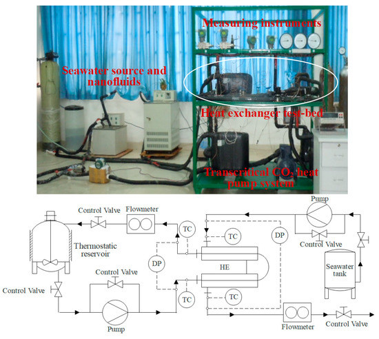
Figure 1.
Heat pump system with seawater source and heat exchanger testbed.
The modified nano-fluid heat exchanger experimental process is as follows. Firstly, a nano-fluid refrigerant is charged in a constant temperature, stirred tank and a constant temperature is set to simulate the heat transfer conditions of the heat pump evaporator. Subsequently, the refrigerant in the constant temperature tank is transported by the circulation pump to the tube side of the coaxial sleeve heat exchanger at a constant flow rate to exchange heat with the seawater. After measuring its temperature difference, pressure drop and flowrate, it returns to the constant temperature tank to complete the heat exchange cycle on the heat exchanger tube side. Finally, the seawater is transported from the storage tank to the shell side of the coaxial sleeve heat exchanger by the open pump to exchange heat with the nanofluids on the tube side. After measuring the temperature difference, pressure drop, and flowrate, the seawater is discharged from the open cycle, and the heat exchange on the shell side of the heat exchanger ends. The structure and heat exchange area of the related test heat exchangers is shown in Table 1. The shell-side material of the heat exchanger uses stainless steel to prevent seawater corrosion and pressure. The nickel-copper pipe is used on the tube side of the heat exchanger to enhance heat exchange. The error analysis of relevant parameters about this experiment system was shown in Table 2. All the measurement parameters were recorded by a computer with the data logger system. Error analysis of measurements is calculated by Equation (1), where the x1, x2, etc. and w1, w2, etc. are the independent variables of a measuring result and the uncertainties, respectively.

Table 1.
Dimensions of the heat exchangers.
Table 2.
Measuring the operating parameters of the instrument.
2.2. Properties of Graphene Nanofluid
As shown in Figure 2, a scanning electron microscope (SEM) was used to observe the micrograph of the purchased graphene nanofluid stock solution 5 wt.%. The SEM images of the GnP were provided by the supplier, who gives the GnP images at 15 μm, 10 μm, and 5 μm magnified sizes. It can be seen from the SEM images that, due to the special two-dimensional structure of the graphene sheet, the graphene nanosheets are distributed in a wrinkled shape in the base fluid solution. Figure 3 is a process for preparing nanofluids with different concentrations and testing their thermophysical properties. Firstly, a 5 wt.% graphene nanofluid stock solution purchased from a company in the USA and its glycol-based solution are shown. After being diluted by a certain mass ratio, there are five kinds of nanofluids to be tested (0.01~1 wt.%) with different mass concentrations. Secondly, we added a surfactant to each of the nanofluids to be measured, and put them into an ultrasonic vibration water bath to diffuse the nanoparticles in the solution, adjusting the duration so that the nanosheets completely diffuse into the base liquid. Finally, the dispersion stability of the solution was tested by zeta potential analysis, and then the viscosity and thermal conductivity of the fluids were measured by a rotational viscometer and a thermal constant analyzer.
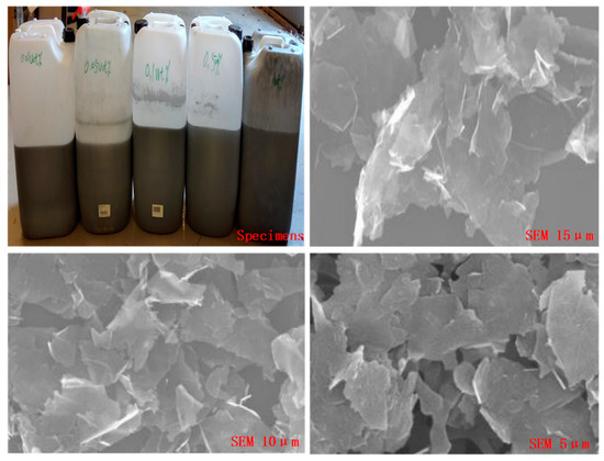
Figure 2.
Nanofluids samples views of the experiment and SEM image of GnP.
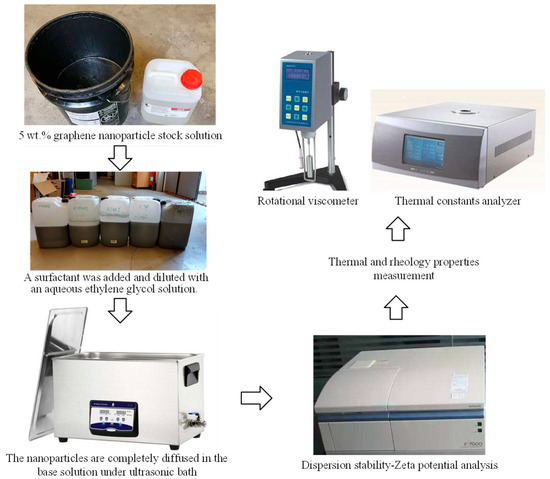
Figure 3.
Graphene nanofluid preparation and the physical property measurement process.
In summary, the thermal properties of the five graphene nanofluids are shown in Table 3. It can be seen that as the concentration of nanoparticles increases, the thermal conductivity and viscosity coefficient of the fluid to be measured are also increasing. When the mass concentration reaches 1.0, the viscosity of the graphene nanofluid will increase rapidly, and the value measured by the rotational viscometer exceeds three times that of the base fluid. Additionally, their density and specific heat capacity can be given according to the following empirical formulas. For detailed processes and analysis, refer to references [40,41].
where the ρ and cp are density and specific heat of the GnP nanofluids, the ϕ indicates the volume fraction of the nanoparticles, and subscripts nf, bf and np indicate nanofluid, base fluid and nanoparticles, respectively.
Table 3.
Thermal properties of nanofluids compared to base fluids.
3. Exergy Transfer Model and Data Reduction
The traditional evaluation of the energy efficiency of heat exchangers and the use of nanofluids to enhance heat transfer analysis are limited to changes in related parameters such as Nusselt number, Reynolds number, heat transfer rate, pumping and convective heat transfer coefficients [42,43]. To dig deep into the energy transfer, utilization and loss caused by the use of nanofluids in heat exchangers, this paper uses the idea of heat exchanger effectiveness to build an exergy transfer model using exergy analysis and exergy transfer theory. It is expected to reveal the intrinsic energy transfer, utilization and loss of nanofluids in the enhanced heat transfer process in heat exchangers from the perspective of exergy transfer.
The exergy loss in the heat exchanger includes two parts caused by the limited heat transfer temperature difference and the fluid viscous flow resistance. Therefore, it is assumed that the flow and heat transfer processes in the heat exchanger are in a stable state, the axial heat conduction and external heat dissipation are ignored, the nanofluid working medium is stable in physical properties, and the working temperature is above the ambient temperature. The differential expression of the specific exergy change of the working medium in the heat exchanger in this paper is given as:
where, cp is specific heat at constant pressure, v is the specific volume of the working medium, TΘ is the environment temperature. For incompressible fluids, v is considered to be constant in normal physical properties and is brought into Equation (4) to obtain:
By integrating the Equation (5), it can obtain:
where P is pressure, T is temperature, m is mass flow of medium, f is the friction factor, u is the velocity of the medium, d is the equivalent diameter, ρ is the density of the working medium, L is the length of the heat exchanger, and the subscripts i and o are the inlet and outlet of the heat exchanger. After obtaining the above expression, the exergy transfer effectiveness εe of the heat exchanger is defined as the actual exergy change of the target heat exchange medium compared to its maximum possible exergy change. For the heat exchanger of this study, the target medium is cold fluid, which benefits from the increase of the cold fluid (graphene nanofluid refrigerant) heat exergy and its consumption is the reduction of the hot fluid (seawater) heat exergy. The maximum possible exergy change of the medium is the maximum exergy change in the ideal state of the countercurrent, i.e., the case of the pressure exergy loss of the countercurrent is 0, after that:
Define a series of dimensionless numbers:
then
putting into Equation (8) to simplify, it can get:
where D is the heat capacity ratio of the cold and hot fluid, and φ is the heat transfer effectiveness of the heat exchanger. Relevant formulas used in other analyses are shown in Table 4.
Table 4.
Mathematical formulas used in the correlation analysis of this study.
4. Results and Discussion
4.1. Performance Analysis of Heat Exchanger
To clarify the influence of nanofluids on the enhancement of convective heat transfer, the changing trend of the ratio of heat conduction resistance to convective heat transfer resistance at the bottom of laminar fluid flow was explored. Six groups (1 wt.%, 0.5 wt.%, 0.1 wt.%, 0.05 wt.%, 0.01 wt.%, 0 wt.%) of graphene nanofluids with different mass fractions were used for the following experimental study, and their base fluid was 50 wt.%:50 wt.% ethylene glycol aqueous solution. As shown in Figure 4, its influence on the heat transfer performance of coaxial sleeve heat exchanger and the change of Nusselt number with Reynolds number. The results show that the increase of the Reynolds number increases the disturbance of the fluid and destroys the flow boundary layer. The more intense the convective heat transfer of the fluid in the tube, the stronger its heat transfer performance. Additionally, as the concentration of graphene nanoparticles increases, the heat transfer performance also improves. It can be explained that the thermal conductivity of the nanoparticles is significantly higher than that of the base fluid, so as the concentration of the nanofluid increases, the thermal conductivity of the working fluid will be greater than that of the base fluid. In addition, graphene nanoparticles are subjected to Brownian forces in nanofluids to perform irregular Brownian diffusion and thermal diffusion movement [40,41,42]. It makes micro-convection between the nanoparticles and the base fluid, enhances the energy transfer between the nanoparticles and the base fluid, sharpens the destruction of the boundary layer, enhances disturbance, and enhances heat transfer. However, with the increase in the concentration of graphene nanoparticles, the viscosity of the nanofluid continues to increase. If a high Nusselt number is to be maintained, a large amount of pump work is consumed [42]. In the perspective of energy conservation, it is not economical to increase the mass fraction of graphene nanoparticles to obtain a small thermal conductivity gain. From the change trend of the ratio of the thermal resistance to the convective heat transfer resistance at the bottom of the fluid laminar flow, the heat transfer enhancement rate from 0.01% to 0.1% is greater than the heat transfer enhancement rate from 0.1% to 1%. These results can increase the heat transfer gain by about 7% or more.
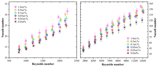
Figure 4.
Effects of nanofluids mass fraction on Nusselt number in a laminar and turbulent flow.
The effect of graphene nanofluids with different mass fractions on the friction resistance coefficient of coaxial sleeve heat exchangers is shown in Figure 5. The root mean square error (RMSE) measured during the experiment is less than ±7.4%, and the relevant trend is well reflected by the error bars and relevant test points. It is clear that the friction factor increases as the mass fraction of graphene nanoparticles increase at similar Reynolds numbers. It is because the friction factor is positively related to the viscosity of the fluid, and the viscosity of the nanofluid increases with the increase of the nanoparticle mass fraction, so the friction factor increases. In addition, in laminar and turbulent flows, the friction factor decreases as the Reynolds number increases. This is due to the negative correlation between the friction factor and the square of the flow velocity. Therefore, in addition to changing the viscosity of the fluid, increasing the nanoparticle concentration will not cause other properties to affect the friction factor.
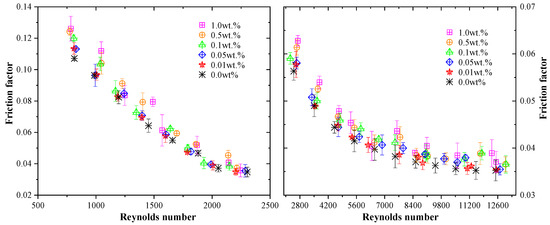
Figure 5.
Effects of nanofluids mass fraction on friction factor in laminar and turbulent flow.
The above analysis only demonstrated the positive effects of increasing flow rate and graphene nanoparticle concentration on characterizing enhanced heat transfer. However, the corresponding friction factor will also increase, and the energy efficiency evaluation of the heat exchanger is simply the result of strengthening the trade-off between the enhanced heat transfer and drag coefficient [40,41]. To further quantitatively analyze the effects of different graphene nanofluid concentrations and flow rates on the performance of heat exchangers, Figure 6 shows the relationship between the pump work and thermal efficiency of the heat exchanger. The results show that, under the experimental conditions, the heat transfer effectiveness of the six measured nanofluids in the heat exchanger gradually increases with the increase of the pump work. The increase in heat exchange performance of the heat exchanger is often accompanied by a pressure drop or pump power consumption, which is in line with the first law of thermodynamics. Secondly, due to the increase in the heat transfer effectiveness of the heat exchanger caused by different concentrations of graphene nanofluids, the increase in unit pump work is greater than the increase in heat exchange capacity. The heat transfer effectiveness of graphene nanofluids at the concentration of 0.01~0.1 wt.% was greater than 0.5~1 wt.%. This indicates that graphene nanofluids with a concentration above 0.1 wt.% in the heat exchanger can improve the heat transfer by means of a greater thermal conductivity of the fluid, but also cause greater frictional resistance and consume more pump work.
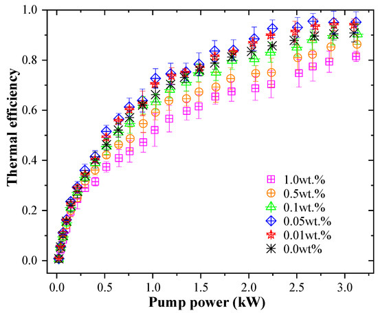
Figure 6.
Pump power versus thermal efficiency of heat exchanger.
Figure 7 shows the relationship between Peclet number on the nanofluid side of the heat exchanger and the convective heat transfer coefficient of the fluid. The heat transfer Peclet number is the product of the Reynolds number and Prandtl number. Its physical meaning is the ratio of convective heat transfer to fluid heat transfer under forced motion. It takes into account both the momentum and the heat diffusivity, i.e., it also measures the density, specific heat, thermal conductivity, and flowrate. The effect of this dimensionless number on the convection heat transfer coefficient of the heat exchanger while increasing the thermal conductivity of the fluid is now given. The results show that as the Peclet number increases, the convective heat transfer coefficients of all measured fluids gradually increase. At the concentration of 0.01~0.1 wt.%, the convective heat transfer coefficient of graphene nanofluids was higher than that of base fluid (0 wt.%). It is because the heat transfer improvement effect brought by the addition of nanoparticles is greater than the increase in its thermal resistance. The convective heat transfer coefficient at the concentration of 0.5~1 wt.% was lower than that of the base fluid, and the thermal resistance of the heat exchanger on the nanofluid side increases sharply. In this interval, the increase of the nanofluid concentration causes the convective heat transfer coefficient to decrease.
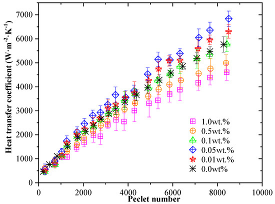
Figure 7.
Convective heat transfer coefficient versus the Peclet number.
4.2. Energy Transfer Efficiency Analysis
The exergy loss in the heat exchanger includes two parts caused by the limited heat transfer temperature difference and the fluid viscous flow resistance. Therefore, the exergy transfer function is used to analyze the influence of the two factors on the energy transfer of the heat exchanger, i.e., the enhanced heat transfer caused by the thermal conductivity of the nanofluid and the loss of pump power caused by its viscosity increase. Figure 8 shows the changing trend of the influence of different concentrations of graphene nanofluids on the exergy transfer effectiveness of the heat exchanger under different NTU conditions. The NTU defines the ratio of the total heat conductance of the fluid (i.e., the inverse of the heat transfer heat resistance of the heat exchanger) to the heat capacity of the fluid, which is an indicator of the comprehensive technical and economic efficiency of the reaction heat exchanger. Since the experimentally tested heat exchanger has a certain volume, it only changes the flow rate and heat capacity of the hot and cold fluids. Therefore, under countercurrent conditions, as the NTU increases, the exergy transfer effectiveness of the graphene nanofluid side in the heat exchanger gradually increases. It can be expected that the final value will approach one, which is the case of infinite flow velocity. Besides, when at a certain NTU value, the heat exchanger has a better exergy transfer effectiveness when the nanoparticle concentration is in the range of 0.01~0.1 wt.% compared to the range of 0.5~1 wt.%. It is because the viscosity of the heat transfer medium and the pump work lost gradually increase as the concentration increases, and the effect of related energy dissipation of graphene nanofluids at concentrations above 0.1 wt.% exceeds the benefits of enhanced heat transfer.
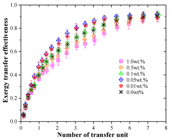
Figure 8.
Effects of nanofluids mass fraction on exergy transfer effectiveness at different NTU.
Figure 9 shows the effect of the concentration of graphene nanofluid on the heat transfer effectiveness of heat exchangers under different conditions of heat capacity ratio of cold and hot fluid. In this study, the graphene nanofluid was defined as the benefit fluid, and the increase in heat exergy of the cold fluid was obtained, while the decrease in heat exergy of the hot fluid was consumed. The exergy transfer effectiveness of graphene nanofluids with different concentrations showed different variation trends, and the heat exchangers with concentrations of 0.01~0.1 wt.% had better performance than those with concentrations of 0.5~1 wt.%. It is because the exergy loss includes two parts caused by the limited heat transfer temperature difference and the fluid viscous flow resistance. The enhanced heat transfer effect brought by the lower concentration of graphene nanofluid is greater than the effect of its fluid viscosity on performance. When the concentration of the graphene nanofluid is too high, the resistance caused by the increase in viscosity will exceed the enhanced heat transfer gain brought by the nanofluid, leading to a significant decrease in the exergy transfer effectiveness, which meets the definition of Equation (11). Besides, the exergy transfer effectiveness of graphene nanofluids in heat exchangers decreases with increasing D and eventually approaches a constant value. It is because for a non-phase change heat exchanger, the smaller the change in the heat capacity ratio of the cold and hot fluid in the heat exchanger is equivalent to the smaller the temperature difference between the heat exchanger and the outside, the greater the corresponding effectiveness. Therefore, when designing a single-phase heat exchanger without phase change, it is important that the hot and cold fluids have an approximate heat capacity ratio so that a high exergy transfer effectiveness can be achieved.
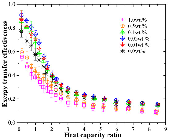
Figure 9.
Effects of nanofluids mass fraction on exergy transfer effectiveness at different heat capacity ratios.
5. Conclusions
This paper focuses on the heat pump technology for the energy saving and emission reduction of maritime ships and carries out the experimental test and analysis based on the first and second laws of thermodynamics for a heat exchanger with a graphene nanofluids refrigerant in a transcritical CO2 heat pump system. Firstly, the effect of the enhanced heat transfer and fluid resistance factor in the heat exchanger using different concentrations of graphene nanofluids was studied. Secondly, based on the heat transfer effectiveness and exergy efficiency of the heat exchanger, a heat exchanger exergy transfer model was theoretically established. Finally, exergy transfer was evaluated for various working conditions of the graphene nanofluid heat exchanger with different concentrations. The main conclusions are as follows:
(1) Based on the comparison of equal Re numbers under laminar and turbulent conditions, the thermophysical properties of GnP nanofluids are the main factors affecting the heat transfer performance and fluid resistance factor of heat exchangers. Under the same Re number conditions, both the Nu number and the heat transfer factor increase to varying degrees with the increase of nanoparticle concentration.
(2) According to the further analysis of the first law of thermodynamics, it can be obtained that the proper increase of pump work and Pe number can significantly increase the heat transfer efficiency and convective heat transfer coefficient of the nanofluid. The heat transfer efficiency of the graphene nanofluids at unit pump work was greater than 0.5~1 wt.%, and the convective heat transfer coefficient of the graphene nanofluids was higher than that of the base fluid at 0.01~0.1 wt.%.
(3) The exergy transfer effectiveness of the heat exchanger in this study defines the graphene nanofluid as the benefit fluid, gains an increase in the exergy of the cold fluid heat, and consumes a decrease in the exergy of the hot fluid heat. The graphene nanofluids with concentrations of 0.01~0.1 wt.% had better exergy transfer effectiveness than those with concentrations of 0.5~1 wt.% in the heat exchanger. The enhanced heat transfer effect of the lower concentration of graphene nanofluid is greater than the effect of its viscosity on performance. When the concentration of graphene nanofluid is too high, the resistance caused by the increase in viscosity will exceed the enhanced heat transfer gain brought by the nanofluid, leading to a significant decrease in the exergy transfer effectiveness.
Author Contributions
Z.W. and F.H. conducted the experiments and wrote the paper. Z.W. analyzed the results. Y.J. gave some suggestions and carried on project administration/funding acquisition. W.L. commented on the paper. All authors have read and agreed to the published version of the manuscript.
Funding
This work was funded by the Fundamental Research Funds for the Central Universities (No. 3132020, 3132019331), the National Natural Science Foundation of China (No. 51906026). Their support is gratefully acknowledged.
Conflicts of Interest
The authors declare no conflict of interest.
Nomenclature
| A | area of surface-heat transfer (m2) |
| cp | heat capacity (J·kg−1·K−1) |
| d | hydraulic diameter (m) |
| D | heat capacity ratio |
| e | exergy (W) |
| ΔE | specific exergy (W) |
| f | friction factor |
| h | heat transfer coefficient (W·m−2·K−1) |
| L | heat transfer length (mm) |
| k | thermal conductivity (W·m−1·K−1) |
| m | mass flow rate (kg·s−1) |
| Nu | Nusselt number |
| ΔP | pressure drop (kPa) |
| Pe | Peclet number |
| Pr | Prandtl number |
| q | heat (W) |
| Q | heat flux (W) |
| Re | Reynolds number |
| s | cross-sectional area (m2) |
| T | temperature (K) |
| U | overall heat transfer coefficient (W·m−2·K−1) |
| v | specific volume (m3·kg−1) |
| Pw | pump power (kW) |
| μ | dynamic viscosity (Pa·s) |
| u | velocity (m·s−1) |
| Greek symbols | |
| εE | exergy transfer effectiveness |
| ρ | density (kg·m−3) |
| ϕ | volume concentration |
| φ | thermal efficiency |
| Subscripts | |
| bf | base fluid |
| exp | experimental |
| c, h | cold or hot side |
| nf | nanofluid |
| i, o | inlet or outlet |
| Θ | environment |
| Abbreviations | |
| EGW | ethylene glycol-water |
| GnP | graphene nanoplatelets |
| CHTC | convective heat-transfer coefficient |
| ID/OD | inner tube/outer tube |
| HVAC | heating ventilation air conditioning |
| TC | thermocouple |
| DP | differential pressure |
| HE | heat exchanger |
| RMSE | root-mean-square error |
References
- Han, F.; Wang, Z.; Ji, Y.; Li, W. Energy analysis and multi-objective optimization of waste heat and cold energy recovery process in LNG-fueled vessels based on a triple organic Rankine cycle. Energy Convers. Manag. 2019, 195, 561–572. [Google Scholar] [CrossRef]
- Trivyza, N.L.; Rentizelas, A.; Theotokatos, G. Impact of carbon pricing on the cruise ship energy systems optimal configuration. Energy 2019, 175, 952–966. [Google Scholar] [CrossRef]
- Benamara, H.; Hoffmann, J.; Youssef, F. Maritime Transport: The Sustainability Imperative. In Sustainable Shipping; Springer: Cham, Switzerland, 2019; pp. 1–31. [Google Scholar]
- Goldsworthy, B.; Goldsworthy, L. Assigning machinery power values for estimating ship exhaust emissions: Comparison of auxiliary power schemes. Sci. Total Environ. 2019, 657, 963–977. [Google Scholar] [CrossRef] [PubMed]
- Valencia Ochoa, G.; Acevedo Peñaloza, C.; Duarte Forero, J. Thermoeconomic optimization with PSO Algorithm of waste heat recovery systems based on organic rankine cycle system for a natural gas engine. Energies 2019, 12, 4165. [Google Scholar] [CrossRef]
- Zhao, Z.; Zhang, Y.; Mi, H.; Zhou, Y.; Zhang, Y. Experimental research of a water-source heat pump water heater system. Energies 2018, 11, 1205. [Google Scholar] [CrossRef]
- Valarezo, A.S.; Sun, X.Y.; Ge, T.S.; Dai, Y.J.; Wang, R.Z. Experimental investigation on performance of a novel composite desiccant coated heat exchanger in summer and winter seasons. Energy 2019, 166, 506–518. [Google Scholar] [CrossRef]
- Fossa, M. The temperature penalty approach to the design of borehole heat exchangers for heat pump applications. Energy Build. 2011, 43, 1473–1479. [Google Scholar] [CrossRef]
- Andrei, P. Study Regarding Marine Heat Pump; Analele Universitatii Maritime Constanta: Constanta, Romania, 2012; Volume 13, pp. 143–146. [Google Scholar]
- Zheng, W.; Zhang, H.; You, S.; Ye, T. Numerical and experimental investigation of a helical coil heat exchanger for seawater-source heat pump in cold region. Int. J. Heat Mass Transf. 2016, 96, 1–10. [Google Scholar] [CrossRef]
- Liu, L.; Wang, M.; Chen, Y. A practical research on capillaries used as a front-end heat exchanger of seawater-source heat pump. Energy 2019, 171, 170–179. [Google Scholar] [CrossRef]
- Ezgi, C.; Girgin, I. Design and thermodynamic analysis of a steam ejector refrigeration/heat pump system for naval surface ship applications. Entropy 2015, 17, 8152–8173. [Google Scholar] [CrossRef]
- Yun, S.K. Study on the performance characteristics of a new CO2 auto-cascade heat pump system. J. Korean Soc. Mar. Eng. 2017, 41, 191–196. [Google Scholar] [CrossRef]
- Priarone, A.; Silenzi, F.; Fossa, M. Modelling Heat Pumps with Variable EER and COP in EnergyPlus: A Case Study Applied to Ground Source and Heat Recovery Heat Pump Systems. Energies 2020, 13, 794. [Google Scholar] [CrossRef]
- Hafner, I.A.; Gabrielii, C.H.; Widell, K. Refrigeration Units in Marine Vessels: Alternatives to HCFCs and High GWP HFCs; Nordic Council of Ministers: Copenhagen, Denmark, 2019; pp. 1–90.
- Chen, X.; Li, Z.; Zhao, Y.; Jiang, H.; Liang, K.; Chen, J. Modelling of refrigerant distribution in an oil-free refrigeration system using R134a. Energies 2019, 12, 4792. [Google Scholar] [CrossRef]
- Bobbo, S.; Fedele, L.; Curcio, M.; Bet, A.; De Carli, M.; Emmi, G.; Poletto, F.; Tarabotti, A.; Mendrinos, D.; Mezzasalma, G.; et al. Energetic and exergetic analysis of low global warming potential refrigerants as substitutes for R410A in ground source heat pumps. Energies 2019, 12, 3538. [Google Scholar] [CrossRef]
- López Paniagua, I.; Jiménez Álvaro, Á.; Rodríguez Martín, J.; González Fernández, C.; Nieto Carlier, R. Comparison of transcritical CO2 and conventional refrigerant heat pump water heaters for domestic applications. Energies 2019, 12, 479. [Google Scholar] [CrossRef]
- Wang, Z.; Li, Y. Layer pattern thermal design and optimization for multistream plate-fin heat exchangers—A review. Renew. Sustain. Energy Rev. 2016, 53, 500–514. [Google Scholar] [CrossRef]
- Zhao, Z.; Zhou, Y.; Ma, X.; Chen, X.; Li, S.; Yang, S. Effect of different zigzag channel shapes of PCHEs on heat transfer performance of supercritical LNG. Energies 2019, 12, 2085. [Google Scholar] [CrossRef]
- Pons, M. Exergy Analysis and process optimization with variable environment temperature. Energies 2019, 12, 4655. [Google Scholar] [CrossRef]
- Lillo, G.; Mastrullo, R.; Mauro, A.W.; Trinchieri, R.; Viscito, L. Thermo-economic analysis of a hybrid ejector refrigerating system based on a low grade heat source. Energies 2020, 13, 562. [Google Scholar] [CrossRef]
- Bejan, A.; Lorente, S. Constructal theory of generation of configuration in nature and engineering. J. Appl. Phys. 2006, 100, 041301. [Google Scholar] [CrossRef]
- Alic, F. Entransy dissipation analysis and new irreversibility dimension ratio of nanofluid flow through adaptive heating elements. Energies 2020, 13, 114. [Google Scholar] [CrossRef]
- Sun, Y.; Wang, X.; Long, R.; Yuan, F.; Yang, K. Numerical Investigation and Optimization on Shell Side Performance of a Shell and Tube Heat Exchanger with Inclined Trefoil-Hole Baffles. Energies 2019, 12, 4138. [Google Scholar] [CrossRef]
- Shen, S.; Qian, Z.; Ji, B. Numerical Analysis of Mechanical Energy Dissipation for an Axial-Flow Pump Based on Entropy Generation Theory. Energies 2019, 12, 4162. [Google Scholar] [CrossRef]
- Preißinger, M.; Brüggemann, D. Thermoeconomic evaluation of modular organic Rankine cycles for waste heat recovery over a broad range of heat source temperatures and capacities. Energies 2017, 10, 269. [Google Scholar] [CrossRef]
- Wu, Z.; You, S.; Zhang, H.; Fan, M. Mathematical Modeling and Performance Analysis of Seawater Heat Exchanger in Closed-Loop Seawater-Source Heat Pump System. J. Energy Eng. 2019, 4, 04019012. [Google Scholar] [CrossRef]
- Alam, T.; Kim, M.H. A comprehensive review on single phase heat transfer enhancement techniques in heat exchanger applications. Renew. Sustain. Energy Rev. 2018, 81, 813–839. [Google Scholar] [CrossRef]
- Sun, X.H.; Yan, H.; Massoudi, M.; Chen, Z.H.; Wu, W.T. Numerical simulation of nanofluid suspensions in a geothermal heat exchanger. Energies 2018, 11, 919. [Google Scholar] [CrossRef]
- Aprea, C.; Greco, A.; Maiorino, A.; Masselli, C. Enhancing the heat transfer in an active barocaloric cooling system using ethylene-glycol based nanofluids as secondary medium. Energies 2019, 12, 2902. [Google Scholar] [CrossRef]
- Kristiawan, B.; Wijayanta, A.T.; Enoki, K.; Miyazaki, T.; Aziz, M. Heat Transfer Enhancement of TiO2/water nanofluids flowing inside a square minichannel with a microfin structure: A numerical investigation. Energies 2019, 12, 3041. [Google Scholar] [CrossRef]
- Ramirez-Tijerina, R.; Rivera-Solorio, C.; Singh, J.; Nigam, K.D.P. Numerical study of heat transfer enhancement for laminar nanofluids flow. Appl. Sci. 2018, 8, 2661. [Google Scholar] [CrossRef]
- Qi, C.; Liu, M.; Wang, G.; Pan, Y.; Liang, L. Experimental research on stabilities, thermophysical properties and heat transfer enhancement of nanofluids in heat exchanger systems. Chin. J. Chem. Eng. 2018, 26, 2420–2430. [Google Scholar] [CrossRef]
- Ghozatloo, A.; Rashidi, A.; Shariaty-Niassar, M. Convective heat transfer enhancement of graphene nanofluids in shell and tube heat exchanger. Exp. Therm. Fluid Sci. 2014, 53, 136–141. [Google Scholar] [CrossRef]
- Sadeghinezhad, E.; Mehrali, M.; Saidur, R.; Mehrali, M.; Latibari, S.T.; Akhiani, A.R.; Metselaar, H.S.C. A comprehensive review on graphene nanofluids: Recent research, development and applications. Energy Convers. Manag. 2016, 111, 466–487. [Google Scholar] [CrossRef]
- Arshad, A.; Jabbal, M.; Yan, Y.; Reay, D. A review on graphene based nanofluids: Preparation, characterization and applications. J. Mol. Liq. 2019, 279, 444–484. [Google Scholar] [CrossRef]
- Wang, Z.; Gong, Y.; Wu, X.H.; Lu, Y. Thermodynamic analysis and experimental research of transcritical CO2 cycle with internal heat exchanger and dual expansion. Int. J. Air Cond. Refrig. 2013, 21, 1350005. [Google Scholar] [CrossRef]
- Wang, Z.; Han, F.; Sundén, B. Parametric evaluation and performance comparison of a modified CO2 transcritical refrigeration cycle in air-conditioning applications. Chem. Eng. Res. Des. 2018, 131, 617–625. [Google Scholar] [CrossRef]
- Wu, Z.; Wang, L.; Sunden, B. Pressure drop and convective heat transfer of water and nanofluids in a double-pipe helical heat exchanger. Appl. Therm. Eng. 2013, 60, 266–274. [Google Scholar] [CrossRef]
- Wang, Z.; Wu, Z.; Han, F.; Wadsö, L.; Sundén, B. Experimental comparative evaluation of a graphene nanofluid coolant in miniature plate heat exchanger. Int. J. Therm. Sci. 2018, 130, 148–156. [Google Scholar] [CrossRef]
- Tariq, R.; Zhan, C.; Ahmed Sheikh, N.; Zhao, X. Thermal performance enhancement of a cross-flow-type Maisotsenko heat and mass exchanger using various nanofluids. Energies 2018, 11, 2656. [Google Scholar] [CrossRef]
- Wang, Z.; Li, Y. Irreversibility analysis for optimization design of plate fin heat exchangers using a multi-objective cuckoo search algorithm. Energy Convers. Manag. 2015, 101, 126–135. [Google Scholar] [CrossRef]
© 2020 by the authors. Licensee MDPI, Basel, Switzerland. This article is an open access article distributed under the terms and conditions of the Creative Commons Attribution (CC BY) license (http://creativecommons.org/licenses/by/4.0/).