Abstract
In this paper, a parallel estimation system of the stator resistance and the rotor speed is proposed in speed sensorless six-phase induction motor (6PIM) drive. First, a full-order observer is presented to provide the stator current and the rotor flux. Then, an adaptive control law is designed using the Lyapunov stability theorem to estimate the rotor speed. In parallel, a stator resistance identification scheme is proposed using more degrees of freedom of the 6PIM, which is also based on the Lyapunov stability theorem. The main advantage of the proposed method is that the stator resistance adaptation is completely decoupled from the rotor speed estimation algorithm. To increase the robustness of the drive system against external disturbances, noises, and parameter uncertainties, an active disturbance rejection controller (ADRC) is introduced in direct torque control (DTC) of the 6PIM. The experimental results clarify the effectiveness of the proposed approaches.
1. Introduction
Three-phase induction motor drives have become a mature technology in the last years, but investigations into concepts of multiphase induction motor drives are still taking place. Multiphase drive systems have a nearly 40-year history of research and study due to their promising advantages against the conventional three-phase systems. The phase redundancy of the multiphase drives provides extra merits such as fault-tolerant operation, series-connected multimotor drive systems, asymmetry and braking systems. Six-phase induction motors (6PIMs) are known for its fault-tolerant capability, low rate of inverter switches, and low DC-link voltage utilization compared with its three-phase one [1,2,3]. On the other hand, the modular three-phase structure of the 6PIM allows the use of well-known three-phase technologies. The 6PIM is successfully used in special applications, such as electric ships, electric aircrafts, electric vehicles, and melt pumps, where the high reliability and continuity of the operation are critical factors for the system [4]. The phase redundancy of the 6PIM provides the ability of the open-phase fault-tolerant operation without any extra electronic components [5,6].
Among different structures of the 6PIM [4], the asymmetrical 6PIM with double isolated neutral points, which consists of two sets of three-phase windings spatially shifted by 30 electrical degrees, has attracted the interest of many researchers [7,8,9,10]. The traditional three-phase control strategies, including switching table-based direct torque control (ST-DTC) [7], modulation-based DTC [8], the field-oriented control (FOC) [9], and finite control set-model predictive control (FCS-MPC) [10], can be extended to 6PIM (or other multi-phase machines) with some modifications to use more freedom degrees that exist in multi-phase machines. DTC is a well-accepted technique due to its simplicity, quick dynamics, and robustness [11]. The modulation-based DTC strategy offers better phase current, torque, and flux response. On the contrary, this method has more complexity against conventional ST-DTC. The ST-DTC approach has straightforward and simple structure, but it is completely overshadowed by low-order harmonics due to unused voltage vectors in the losses subspaces. To overcome this restriction, the idea of duty cycle control is introduced by several researchers [12,13].
The rapid development of intelligent and high-performance control technologies has also brought about changes in the adjustable speed drive system for different industrial applications [14,15]. To operate safely and reliably under different conditions, there is a lot of debate nowadays about the main control strategy of the system [16,17]. Among different high-performance control strategies of drive systems, the DTC strategy has a straightforward algorithm. The DTC technique is inherently speed sensorless. Nevertheless, if an outer speed loop is added to the DTC, the speed value is also necessary. Sensorless three/multi-phase induction machine drives are widely addressed in the technical literature due to multiple shortcomings of shaft encoders [18,19,20,21,22,23]. To investigate the instability problem of the traditional rotor flux-based model reference adaptive system (MRAS) speed estimators in the regenerating-mode low-speed operation, a stator current-based and back electromotive force-based MRASs are addressed in [19,20], respectively. In [21], two modified adaptation mechanisms are proposed to replace the classical proportional-integral (PI) regulator. The full-order Luenberger and Kalman filter observers are discussed in [22,23], respectively. Providing a DTC drive system with parallel identification of the rotor speed and the stator resistance is a challenging task because the operation of the DTC scheme is severely dependent on the stator resistance. This problem is sporadically reported for three-phase induction machines (3PIMs) [24,25], where the rotor speed and the stator resistance estimators encounter an overlap due to limited freedom degrees of 3PIM. In this paper, the problem of parallel estimation is investigated using more freedom degrees of 6PIM.
The outer speed control loop of the DTC scheme conventionally contains the PI regulator to obtain torque command from speed error. In general, the control law of a PID regulator is a linear combination of proportional-integral-derivative terms, which is suitable for linear systems. For nonlinear systems, such as the 6PIM drive system, the PI regulator has been given a lot of attention due to its simplicity. However, it suffers from multiple problems including: (1) tuning of its parameters; (2) high sensitivity against noise and external disturbances; and (3) loss of efficiency due to oversimplified control law [26,27]. One promising technique to relatively get rid of the drawbacks of PI regulator is active disturbance rejection controller (ADRC) [26,28]. The ADRC is a nonlinear control scheme, which provides a robust control against noises, external disturbances, and parameter uncertainties. For these reasons, the ADRC technique has recently attracted more attention for electric drive systems. To address this issue, a modified FOC scheme based on first-order ADRCs for current and speed control loops is proposed in [29]. A combined active disturbance rejection and sliding-mode controller for an induction motor is presented to achieve total robustness [30].
The aim of this paper is to present an ADRC-based DTC scheme for sensorless 6PIM drives. The speed estimator is based on adaptive full-order observer, and its control law is designed using Lyapunov stability theorem. Besides the speed estimation system, a stator resistance estimator is proposed using additional degrees of freedom of the 6PIM to enhance the robustness of the sensorless DTC strategy against stator resistance uncertainties. The adaptation law for the stator resistance estimator is derived using the Lyapunov stability theorem to ensure its overall convergence.
The rest of this paper is organized as follows. Section 2 introduces the mathematical model of the 6PIM. Section 3 presents the design procedure of the adaptive full-order observer, the speed estimator, and the stator resistance estimator. The DTC scheme of the 6PIM is discussed in Section 4, which includes the ST-DTC scheme, and ADRC in DTC. The experimental results are presented in Section 5. Finally, Section 6 summarizes the findings and concludes the paper.
2. Dynamic Model of 6PIM
There are two popular approaches for modeling of the multi-phase machines: (1) multiple d–q approach [9]; (2) vector space decomposition (VSD) approach [31]. The first method is exclusively used for modular three-phase structures-based multi-phase machines such as six-phase and nine-phase machines. However, the second method can be used for all types of multi-phase machines. In this research, the VSD approach is used, where a 6PIM with distributed windings is modeled in the three orthogonal subspaces, i.e., the , and . Among them, only the variables are in relation with electromechanical energy conversion, while and variables do not actively contribute to the torque production.
The schematic diagram of a six-phase voltage source inverter (VSI)-fed an 6PIM with two isolated neutral points is shown in Figure 1. The transfer between the normal variables and variables is performed by transformation matrix as follows [31]:
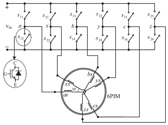
Figure 1.
Six-phase two-level VSI-fed 6PIM.
By applying matrix to the voltage equations in the original six-dimensional system, the 6PIM model can be represented in the three orthogonal submodels, identified as , , and . The voltage space vector equations of the 6PIM in the subspace are written as follows:
The flux linkages are
where , , , R, and L represent voltage, current, flux linkage, resistance, and inductance, respectively, for stator (s subscript) and rotor (r subscript) quantities, and p denotes derivative operator. The electromagnetic torque produced by the 6PIM is expressed as
where P is pole pairs and ⊗ denotes the cross product.
The 6PIM voltage equations in the subspace are the same as a passive R-L circuit as follows:
where is stator leakage inductance.
On the presumption that the stator mutual leakage inductances can be neglected, the 6PIM model in the subspace has the same form of the subspace. However, the applied 6PIM with two isolated neutral points avoids zero-sequence currents because it contains two sets of balanced three-phase windings.
3. Adaptive Full-Order Observer
The block diagram of the proposed and estimators based on the adaptive state observer is shown in Figure 2. It contains the stator current and rotor flux observers, the stator resistance identifier, and the rotor speed estimator, which are discussed below.
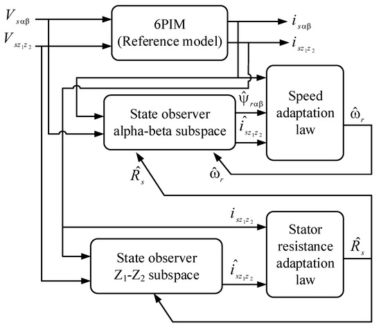
Figure 2.
The block diagram of the proposed parallel estimation system of the stator resistance and the rotor speed based on an adaptive full-order observer.
3.1. Stator Current and Rotor Flux Observers
The general form of state-space model of the 6PIM in the subspace is
Assuming stator current and rotor flux as state variables and using Equations (2) and (3), the elements of state-space representation in subspace will be
with
where is rotor time constant and is leakage coefficient.
The state observer of the 6PIM has a similar form of state-space representation except that an additional compensation term based on error of measurable states and observer gain matrix is added to it. The state observer can be written as
where the marker indicates the estimated values, and is the observer gain matrix. The matrix contains unknown parameters of the 6PIM such as the rotor speed and the stator resistance. These parameters can be estimated by the designing of a suitable adaptation control law with a nonlinear theorem such as a Lyapunov stability theorem. It is worth mentioning here that the matrix also contains the rotor time constant. However, simultaneous estimation of the rotor speed, the rotor time constant, and the stator resistance is challenging because of persistency of excitation conditions problem [32]. Some techniques have recently been developed based on signal injection to provide persistent excitation [33], which suffer from steady-state torque and speed ripples. In this paper, the stator resistance is estimated from additional degrees of freedom of the 6PIM, while the rotor speed is provided using the 6PIM equations in subspace. This procedure provides the stator resistance independent from the rotor speed.
The observer gain matrix must be designed to ensure stability and good dynamic response of the observer at a wide range of the speeds. Using pole-placement method, the elements of matrix is provided as [22,34]
where
where is observer constant gain.
3.2. Stator Resistance Identification
In this paper, a stator resistance adaptation system is proposed using the machine model in the subspace. This method can be utilized for any multi-phase machines. It is completely decoupled from the rotor speed and the rotor time constant, whereas most of the conventional stator resistance estimators, developed for three-phase machines, are related to these parameters. The proposed estimator only depends on the stator leakage inductance , which can be approximately assumed to be constant.
The state-space model of 6PIM in the subspace, with consideration of and as the state variables, can be derived from Equations (7) and (8) as follows:
In this case, the proposed states observer is given by
It should be noted that a correction term is neglected in Equation (21) due to the inherent stability of the observer.
The proposed adaptation law for the stator resistance estimation is
where and are the integral and proportional gains, respectively, and is the stator resistance error signal
The proof for the stator resistance adaptation law is presented in Appendix A.
3.3. Rotor Speed Estimation
In order to design the speed adaptation law, it is considered as an unknown parameter. First, an appropriate positive definite function is chosen as the Lyapunov candidate. Then, the adaptation law is obtained using the Lyapunov criterion to ensure asymptotic stability of the system. The speed adaptation law is
where and are proportional and integral gains, respectively, and is the speed error signal as follows:
The proof for the speed adaptation law is presented in Appendix B.
4. DTC of 6PIM
4.1. ST-DTC Scheme
A six-phase VSI contains overall different voltage space vectors, 60 active, and four zero vectors, where the active voltage vectors are distributed in four non-zero levels depicted in Figure 3. The electrical angle of each sectors is . The 6PIM phase-to-neutral voltages can be calculated as
where is the switching state. When (), the corresponding stator terminal is connected to positive (negative) DC-link rail. The voltage space vectors are given by
where and .
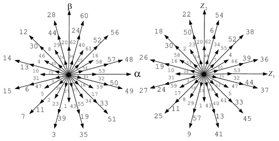
Figure 3.
The (top side) and the (down side) vector subspaces for a six-phase VSI.
The flux estimator is obtained from
and the toque estimator is obtained from (6). In the traditional ST-DTC, the torque and stator flux errors are applied to hysteresis regulators to provide the sign of torque and stator flux . According to gained signals and also the position of stator flux, a proper large voltage vector is selected based on Table 1 during each sampling period. From Figure 3, the corresponding voltage vectors in the subspace will produce large current harmonics, when only large voltage vectors are used to control the torque and flux. Hence, it can alleviate the current harmonics through reduction of the components by applying a combined voltage vector during each sampling period. This technique is referred to as duty cycle control, where a virtual vector (synthesized by large and medium voltage space vectors) is applied to the inverter in each sampling period because the large and medium voltage vectors are in the opposite direction in the subspace (see Figure 3). The duration of the applied vectors is calculated in order to reduce the average volt-seconds in the subspace [4]. The block diagram of the proposed sensorless DTC strategy with the adaptive full-order observer is shown in Figure 4a. In this figure, the speed control loop is based on the ADRC strategy, which will be discussed in the next subsection.

Table 1.
Switching table of DTC strategy.
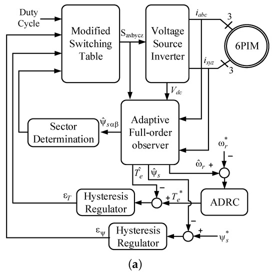
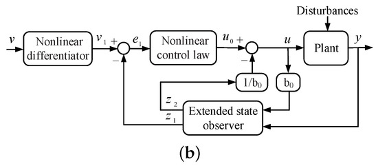
Figure 4.
Block diagram of (a) the proposed sensorless DTC strategy; (b) ADRC.
4.2. ADRC in DTC
To enhance the robustness of the DTC technique against external disturbances and measurement noises, the ADRC is proposed to replace with the conventional PI regulator in the outer speed control loop. The block diagram of ADRC is shown in Figure 4b. It consists of three main elements: (1) nonlinear differentiator; (2) extended state observer; (3) nonlinear control law.
In some industrial applications, the command values are changed as step function, which is not suitable for the control system because of a sudden jump of output and control signals. To solve this problem, the nonlinear differentiator is used, which makes a reasonable transient profile from command signals for tracking [26]. The nonlinear differentiator can be expressed by
where is a nonlinear function as
with
where and are the parameters of the nonlinear differentiator, and h is sampling period.
The extended state observer is an enhanced version of feedback linearization method to compensate the total disturbances of the system. Using this observer, the state feedback term can be estimated online; hence, it is an adaptive robust observer against model uncertainties and external disturbances. The extended state observer is represented as follows:
where the nonlinear function is defined as
where , , , , and are the parameters of the extended state observer.
The conventional PI controller is based on the linear combination of proportional and integral terms of error, which may degrade the performance of the DTC scheme. Different nonlinear combination of error can be presented to overcome this problem. In this paper, the following nonlinear control law is used:
where , , and are the parameters of nonlinear control law.
5. Experimental Validation
5.1. Description of Experimental Setup
The schematic and photograph of the experimental setup are shown in Figure 5a,b, respectively. The principal elements are
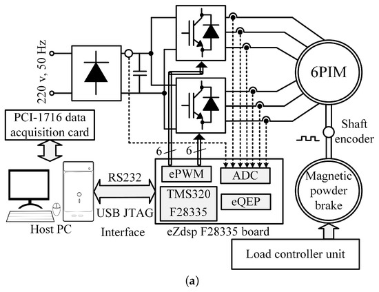
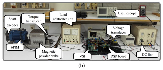
Figure 5.
Experimental setup (a) schematic (b) photograph.
- a TMS320F28335-based digital signal processor (DSP) board.
- two custom-made two-level three-phase VSIs based on BUP 314D IGBTs and LEM LTS 6-NP current transducers.
- an LEM LV25-P voltage transducer.
- an Autonics incremental shaft encoder.
- a magnetic powder brake mechanically coupled to the 6PIM.
- a bridge rectifier.
- a 1-hp three-phase induction motor, which has been rewound to provide an asymmetrical 6PIM. The specifications of the 6PIM are shown in Table 2.
Table 2. The parameters of 6PIM.
5.2. Experimental Results
The performance of the proposed sensorless DTC strategy has been experimentally surveyed using DSP platform, programmed through Code Composer Studio (CCS v.3.3) and MATLAB. The IQmath and digital motor control (DMC) libraries have been used to provide optimized code. A 10 kHz sampling frequency with a 2 s dead-band has been adopted. The experimental results have been captured using an Advantech PCI-1716 data acquisition card (DAQ) and serial port with LABVIEW and MATLAB, respectively. The serial communications interface (SCI) module has been employed to provide a serial connection between host PC and DSP. An incremental shaft encoder has been used to verify the performance of the speed estimation algorithm. All of the experiments have been carried out in sensorless mode as well as closed-loop adaptation of the stator resistance under various test scenarios, emphasizing on the low-speed region.
The experimental results of the proposed parallel estimation system of stator resistance and rotor speed under 50% initial stator resistance mismatch are shown in Figure 6. The speed command is 7% rated speed under rated load torque. In this test, the electric drive is allowed to start with a wrong stator resistance. This causes an error in estimated electromagnetic torque and actual speed. However, the estimated speed and the stator flux follow their reference values because of the controller action. It can be seen that the estimation error of the speed and the electromagnetic torque due to detuned stator resistance are removed within short seconds after activation of the stator resistance estimator at .
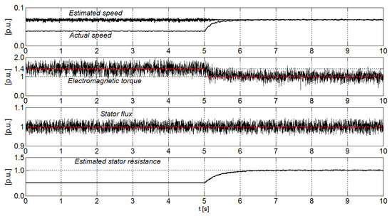
Figure 6.
Experimental results of the proposed parallel estimation system under initial mismatch of stator resistance.
As already mentioned, the proposed parallel estimation system has the merit of avoiding overlap between stator resistance and rotor speed estimators, whereby the stator resistance is independently estimated from rotor speed using additional freedom degrees of 6PIM. The experimental results of estimated stator resistance under speed changes and load change are shown in Figure 7a,b, respectively. In Figure 7a, the speed command is changed as a step function from a very low speed to 17% rated speed, and, in Figure 7b, a load torque is suddenly applied to the motor at . It can be clearly adjudged that the adaptation process of stator resistance is independent of speed and load torque changes.
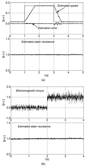
Figure 7.
Experimental results of the estimated stator resistance under (a) speed changes (b) load torque change.
Disturbance-free operation of the ADRC-based speed controller is evaluated through a comparative study of its performance and the conventional PI regulator. The experimental results for the estimated speed under sudden load torque changes at 7% rated speed when the conventional PI and introduced ADRC are utilized as speed controllers are shown in Figure 8. As can be seen, applying the external load torque to the 6PIM leads to a larger overshoot (undershoot), when the conventional PI regulator is employed. The ADRC properly improves the disturbance rejecting capability, which in turn provides a robust performance against load torque changes.
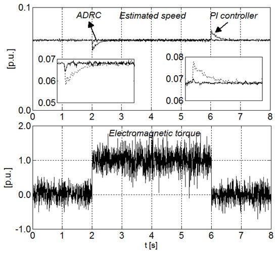
Figure 8.
Experimental results of the estimated speed with PI and ADRC-based speed controllers under load changes.
6. Conclusions
Multiphase electrical machines and drives have different advantages over their traditional three phase counterparts. In recent years, multiple research works have been published to explore the specific advantages of multiphase machines and drives. In this regard, a parallel estimation system of the stator resistance and the rotor speed for direct torque-controlled 6PIM was proposed in this paper. The speed estimator is based on an adaptive full-order observer, which estimates the speed signal using the 6PIM model in the subspace, while the stator resistance estimator employs the 6PIM model in the subspace. Hence, the stator resistance is identified independently of the rotor speed. The rotor speed- and the stator resistance-adaptation laws were derived using the Lyapunov stability theorem. The performance of the proposed sensorless DTC was experimentally investigated, where the obtained results confirmed its capabilities in terms of accuracy as well as no overlap between the stator resistance and the rotor speed estimators. In order to provide a robust performance for the DTC technique against external load torques, the PI regulator was replaced by an ADRC, as a well-known disturbance-free controller. The better performance of the DTC scheme based on ADRC was verified through a comparative study with the conventional PI regulator.
Author Contributions
Conceptualization, methodology, validation, formal analysis, writing–original draft preparation, H.H., M.H.H.; writing—review and editing, resources, A.R.; project administration, T.V.; investigation, A.K.; funding acquisition, D.V.L.; supervision, A.B. All authors have read and agreed to the published version of the manuscript.
Funding
The research has been supported by the Estonian Research Council under grant PSG453 “Digital twin for propulsion drive of autonomous electric vehicle” and was financially supported by Government of Russian Federation (Grant 08-08).
Conflicts of Interest
The authors declare no conflict of interest.
Appendix A. The Design of Adaption Law for Stator Resistance Estimation
The quadratic Lyapunov function for asymptotic stability of the proposed stator resistance estimation system is defined as
where is a positive constant, , is the estimated stator resistance, is the real stator resistance, and is the error matrix of the state variables in the subspace as
The asymptotic stability of the stator resistance estimator is assured when the Lyapunov candidate function is positive definite as well as its time derivative is negative definite. The time derivative of the Lyapunov candidate function is calculated as
With some mathematical manipulation, Equation (A3) can be written as
The first term of Equation (A4) is inherently negative definite. The stability of the system is eventually assured, when the sum of the last two terms of Equation (A4) is zero as
which leads to
where the tuning signal is
A PI regulator is employed to enhance the dynamic behaviour of the proposed estimator, instead of Equation (A6) as
where and are the integral and proportional constants.
Appendix B. The Design of Adaption Law for Speed Estimation
The Lyapunov candidate function for asymptotic stability of the speed estimation system is
where is a positive constant, , and is the error matrix of the estimated and real values in subspace as
In this case, the first-order time derivative of Lyapunov function can be deduced as
The first term of Equation (A11) is guaranteed to be negative definite by suitable adopting of observer gain matrix . The Lyapunov stability criterion is satisfied, if the sum of second and third terms of Equation (A11) is zero. With some calculations, the adaptation law for speed estimator is acquired as
where the tuning signal is
References
- Levi, E.; Bojoi, R.; Profumo, F.; Toliyat, H.A.; Williamson, S. Multiphase induction motor drives—A technology status review. IET Electr. Power Appl. 2007, 1, 489–516. [Google Scholar] [CrossRef]
- Heidari, H.; Rassõlkin, A.; Vaimann, T.; Kallaste, A.; Taheri, A.; Holakooie, M.H.; Belahcen, A. A novel vector control strategy for a six-phase induction motor with low torque ripples and harmonic currents. Energies 2019, 12, 1102. [Google Scholar] [CrossRef]
- Levi, E. Multiphase Electric Machines for Variable-Speed Applications. IEEE Trans. Ind. Electron. 2008, 55, 1893–1909. [Google Scholar] [CrossRef]
- Holakooie, M.H.; Ojaghi, M.; Taheri, A. Direct Torque Control of Six-Phase Induction Motor With a Novel MRAS-Based Stator Resistance Estimator. IEEE Trans. Ind. Electron. 2018, 65, 7685–7696. [Google Scholar] [CrossRef]
- Che, H.S.; Duran, M.J.; Levi, E.; Jones, M.; Hew, W.P.; Rahim, N.A. Postfault Operation of an Asymmetrical Six-Phase Induction Machine With Single and Two Isolated Neutral Points. IEEE Trans. Power Electron. 2014, 29, 5406–5416. [Google Scholar] [CrossRef]
- Lu, H.; Li, J.; Qu, R.; Ye, D. Fault-tolerant predictive current control with two-vector modulation for six-phase permanent magnet synchronous machine drives. IET Electr. Power Appl. 2018, 12, 169–178. [Google Scholar] [CrossRef]
- Holakooie, M.H.; Ojaghi, M.; Taheri, A. Modified DTC of a Six-Phase Induction Motor With a Second-Order Sliding-Mode MRAS-Based Speed Estimator. IEEE Trans. Power Electron. 2019, 34, 600–611. [Google Scholar] [CrossRef]
- Bojoi, R.; Farina, F.; Griva, G.; Profumo, F.; Tenconi, A. Direct torque control for dual three-phase induction motor drives. IEEE Trans. Ind. Appl. 2005, 41, 1627–1636. [Google Scholar] [CrossRef]
- Singh, G.K.; Nam, K.; Lim, S.K. A simple indirect field-oriented control scheme for multiphase induction machine. IEEE Trans. Ind. Electron. 2005, 52, 1177–1184. [Google Scholar] [CrossRef]
- Gregor, R.; Barrero, F.; Toral, S.L.; Duran, M.J.; Arahal, M.R.; Prieto, J.; Mora, J.L. Predictive-space vector PWM current control method for asymmetrical dual three-phase induction motor drives. IET Electr. Power Appl. 2010, 4, 26–34. [Google Scholar] [CrossRef]
- Zaid, S.A.; Mahgoub, O.A.; El-Metwally, K.A. Implementation of a new fast direct torque control algorithm for induction motor drives. IET Electr. Power Appl. 2010, 4, 305–313. [Google Scholar] [CrossRef]
- Hoang, K.D.; Ren, Y.; Zhu, Z.Q.; Foster, M. Modified switching-table strategy for reduction of current harmonics in direct torque controlled dual-three-phase permanent magnet synchronous machine drives. IET Electr. Power Appl. 2015, 9, 10–19. [Google Scholar] [CrossRef]
- Tatte, Y.N.; Aware, M.V. Torque Ripple and Harmonic Current Reduction in a Three-Level Inverter-Fed Direct-Torque-Controlled Five-Phase Induction Motor. IEEE Trans. Ind. Electron. 2017, 64, 5265–5275. [Google Scholar] [CrossRef]
- Rassõlkin, A.; Vaimann, T.; Kallaste, A.; Kuts, V. Digital twin for propulsion drive of autonomous electric vehicle. In Proceedings of the 2019 IEEE 60th International Scientific Conference on Power and Electrical Engineering of Riga Technical University (RTUCON), Riga, Latvia, 7–9 October 2019; pp. 1–4. [Google Scholar]
- Kuts, V.; Tahemaa, T.; Otto, T.; Sarkans, M.; Lend, H. Robot manipulator usage for measurement in production areas. J. Mach. Eng. 2016, 16, 57–67. [Google Scholar]
- Sell, R.; Leier, M.; Rassõlkin, A.; Ernits, J.P. Self-driving car ISEAUTO for research and education. In Proceedings of the 2018 19th International Conference on Research and Education in Mechatronics (REM), Delft, The Netherlands, 7–8 June 2018; pp. 111–116. [Google Scholar]
- Rassõlkin, A.; Sell, R.; Leier, M. Development case study of the first estonian self-driving car, iseauto. Electr. Control Commun. Eng. 2018, 14, 81–88. [Google Scholar] [CrossRef]
- Kumar, R.; Das, S.; Syam, P.; Chattopadhyay, A.K. Review on model reference adaptive system for sensorless vector control of induction motor drives. IET Electr. Power Appl. 2015, 9, 496–511. [Google Scholar] [CrossRef]
- Gadoue, S.M.; Giaouris, D.; Finch, J.W. Stator current model reference adaptive systems speed estimator for regenerating-mode low-speed operation of sensorless induction motor drives. IET Electr. Power Appl. 2013, 7, 597–606. [Google Scholar] [CrossRef]
- Rashed, M.; Stronach, A.F. A stable back-EMF MRAS-based sensorless low-speed induction motor drive insensitive to stator resistance variation. IEE Proc. Electr. Power Appl. 2004, 151, 685–693. [Google Scholar] [CrossRef]
- Holakooie, M.H.; Taheri, A.; Sharifian, M.B. MRAS Based Speed Estimator for Sensorless Vector Control of a Linear Induction Motor with Improved Adaptation Mechanisms. J. Power Electron. 2015, 15, 1274–1285. [Google Scholar] [CrossRef]
- Holakooie, M.H.; Ojaghi, M.; Taheri, A. Full-order Luenberger observer based on fuzzy-logic control for sensorless field-oriented control of a single-sided linear induction motor. ISA Trans. 2016, 60, 96–108. [Google Scholar] [CrossRef]
- Habibullah, M.; Lu, D.D.C. A Speed-Sensorless FS-PTC of Induction Motors Using Extended Kalman Filters. IEEE Trans. Ind. Electron. 2015, 62, 6765–6778. [Google Scholar] [CrossRef]
- Lee, K.B.; Blaabjerg, F. Sensorless DTC-SVM for Induction Motor Driven by a Matrix Converter Using a Parameter Estimation Strategy. IEEE Trans. Ind. Electron. 2008, 55, 512–521. [Google Scholar] [CrossRef]
- Lascu, C.; Boldea, I.; Blaabjerg, F. Direct torque control of sensorless induction motor drives: A sliding-mode approach. IEEE Trans. Ind. Appl. 2004, 40, 582–590. [Google Scholar] [CrossRef]
- Han, J. From PID to Active Disturbance Rejection Control. IEEE Trans. Ind. Electron. 2009, 56, 900–906. [Google Scholar] [CrossRef]
- Mahmudizad, M.; Ahangar, R.A. Improving load frequency control of multi-area power system by considering uncertainty by using optimized type 2 fuzzy pid controller with the harmony search algorithm. World Acad. Sci. Eng. Technol. 2016, 10, 1051–1061. [Google Scholar]
- Wang, G.; Wang, B.; Li, C.; Xu, D. Weight-transducerless control strategy based on active disturbance rejection theory for gearless elevator drives. IET Electr. Power Appl. 2017, 11, 289–299. [Google Scholar] [CrossRef]
- Li, J.; Ren, H.P.; Zhong, Y.R. Robust Speed Control of Induction Motor Drives Using First-Order Auto-Disturbance Rejection Controllers. IEEE Trans. Ind. Appl. 2015, 51, 712–720. [Google Scholar] [CrossRef]
- Alonge, F.; Cirrincione, M.; D’Ippolito, F.; Pucci, M.; Sferlazza, A. Robust Active Disturbance Rejection Control of Induction Motor Systems Based on Additional Sliding-Mode Component. IEEE Trans. Ind. Electron. 2017, 64, 5608–5621. [Google Scholar] [CrossRef]
- Zhao, Y.; Lipo, T.A. Space vector PWM control of dual three-phase induction machine using vector space decomposition. IEEE Trans. Ind. Appl. 1995, 31, 1100–1109. [Google Scholar] [CrossRef]
- Kubota, H.; Matsuse, K. Speed sensorless field-oriented control of induction motor with rotor resistance adaptation. IEEE Trans. Ind. Appl. 1994, 30, 1219–1224. [Google Scholar] [CrossRef]
- Wang, K.; Chen, B.; Shen, G.; Yao, W.; Lee, K.; Lu, Z. Online updating of rotor time constant based on combined voltage and current mode flux observer for speed-sensorless AC drives. IEEE Trans. Ind. Electron. 2014, 61, 4583–4593. [Google Scholar] [CrossRef]
- Yin, Z.; Zhang, Y.; Du, C.; Liu, J.; Sun, X.; Zhong, Y. Research on Anti-Error Performance of Speed and Flux Estimation for Induction Motors Based on Robust Adaptive State Observer. IEEE Trans. Ind. Electron. 2016, 63, 3499–3510. [Google Scholar] [CrossRef]


© 2020 by the authors. Licensee MDPI, Basel, Switzerland. This article is an open access article distributed under the terms and conditions of the Creative Commons Attribution (CC BY) license (http://creativecommons.org/licenses/by/4.0/).