Abstract
The application of the large-capacity energy storage and heat storage devices in an integrated energy system with a high proportion of wind power penetration can improve the flexibility and wind power accommodation capacity of the system. However, the efficiency and cost of the flexible resource should also be taken into consideration when improving the new energy accommodation capacity. Based on these considerations, the authors try to construct a joint optimal scheduling model for day-ahead energy storage and heat storage that considers flexibility. The power supplies and devices will be modeled separately, which enables a universal applicability. The objective function is the minimum cost and wind curtailment. Various practical constraints are taken into account. The mixed integer programming and software GLPK is used to program and solve. The actual operation data of a provincial power grid in northern China is used to conduct simulation analysis in four different working conditions. The results show that the model can maintain economical efficiency under different working conditions. In addition, it can adjust and dispatch various power supplies and devices efficiently, significantly improving wind power accommodation of the system.
1. Introduction
Great changes have taken place in the field of energy development. The only way to achieve sustainable development is to promote energy revolution and develop renewable energy. As a mature renewable energy, wind power has been developed and utilized on a large scale. In 2050, 60% of China’s electricity will come from renewable sources [1]. By then, the installed capacity of wind power generation will reach 2396 GW, and the proportion of power generated by wind will be 35.2%. However, there still exists the problem of wind curtailment in its power system, which has become an urgent challenge for the healthy development of the wind power industry.
The insufficient flexibility of a power system is the main reason for difficulty in wind power accommodation [2,3]. China has a vast area and there are abundant high-quality wind energy resources in the northern regions. However, their power systems are dominated by thermal power units. In their actual operation, peak-shaving is usually undertaken by thermal power units. The penetration ratio of wind power has been increasing in recent years, and its reverse peak regulation characteristics and large fluctuations have brought certain difficulties to the formulation of the dispatching plan. As a result, the dispatching department usually adopts means of wind curtailment or even shuts down the units to ensure the stable operation of the power grid, which leads to energy waste and economy loss. Furthermore, during the heating period of more than half a year in north China, the combined heat and power (CHP) units usually are operated under the mode of “Following the thermal load” (FTL) in order to meet the demand for heating [4,5] (Refer to Table A1 for all acronyms). The demand for thermal load at night is high but the electrical load is low. The electric power generation level of the CHP unit adopting the mode of “FTL” is relatively higher, and the remaining power space is small. It is in this period that the wind resource is abundant. So, the application of “FTL” results in a large amount of wind curtailment. Nowadays, thermal power (TP) and CHP units have been transformed by installing heat storage devices (HSD) and electric boilers (EB) [6,7,8,9,10,11,12,13,14]. In addition, new flexible resources such as energy storage devices (ESD) and pumped storage power stations have been further developed [15,16,17,18,19]. The advancement in these two aspects provides new options for the peak regulation of power systems. In References [9,10], by adding HSDs, the “FTL” mode of CHP units was decoupled, and its adjustment ability was improved; Reference [11] systematically summarized the comprehensive energy system, which goes beyond the scope of the power system. The use of large-capacity heat storage will improve the optimization capacity of the energy system over a wide time and space range, and increase the capacity of renewable energy consumption. However, this paper did not provide any analysis of specific implementation modes and application effects. Reference [12] proposed a wind power consumption method for adding an EB to a CHP unit, which reduced the cost of power generation and improved the capacity for wind power consumption. Reference [15] proposed the basic idea of using ESDs to solve these problems.
The effectiveness of the method for solving the problem of wind curtailment by improving the flexibility of the system has been confirmed in practice. On January 1, 2017, the operation rules of northeast electric auxiliary service market were published. After a six-month implementation period, the curtailment rate in northeast China has been greatly reduced. Curtailment rates in Heilongjiang, Jilin, and Liaoning dropped to 16%, 24%, and 9%, respectively. By the first half of 2019, curtailment rates in the three provinces had dropped to 2.0%, 3.3%, and 0.6%. However, the consequent increase in auxiliary service costs has also attracted attention from all parties. On November 5, 2019, the Comprehensive Department of the National Energy Administration issued the "Notice on the Relevant Situation of Electric Power Ancillary Services in the First Half of 2019". Compensation expenses were 2.49 billion yuan, seeing an increase of 69.4% year-on-year, of which peak shaving compensation expenses were 2.45 billion yuan, an increase of 73.8% year-on-year. This phenomenon has led people to think about some new questions: Is the use of flexible resources efficient? Can the optimization of dispatching reduce the overall auxiliary service costs while improving the power grid’s ability to absorb new energy?
Based on problems above, this paper builds a joint optimization and scheduling model for electric storage and heat storage that considers flexibility. By using electric boilers and heat storage devices, the rigid constraint of “FTL” for CHP units is decoupled. The fluctuation and intermittency of the output of renewable energy and the peak-valley characteristics of the power load are further stabilized by energy storage devices. The cost of each flexible resource scheduling is taken into consideration in the objective function. Effective resource dispatch improves the flexibility of the system. While improving the system’s ability to absorb new energy, the model also ensures the economic efficiency of the system.
The paper is structured as follows: In Section 2, the operating characteristics of electric-heat integrated energy system are introduced. The powers sources and devices models are described in detail in Section 3. The overall optimal scheduling model is provided in Section 4, and the case study is presented in Section 5. Finally, the conclusions are drawn in Section 6.
2. Electric-Heat Integrated Energy System
In the electric-thermal integrated energy system, the use of HSDs can help achieve thermal-electrolytic decoupling. In addition, ESDs can match the fluctuating and intermittent new energy output. It can coordinate with TP units, CHP units, EBs, and HSDs to increase flexibility, further improving the system’s new energy consumption. In addition, the thermal system and electrical system are also highly complementary in physical characteristics. On the one hand, the transmission and distribution network of the thermal system has certain heat storage characteristics. Compared with the "time-to-use" of the power of the electrical system, a thermal system has greater inertia. As a result, it has a natural tolerance to the volatility and intermittency of electricity. On the other, an electric power system has a large spatial range of transmission and optimized allocation capabilities that a thermal system lacks. If the function of energy storage can be added to it, then the inertia and flexibility of a thermal system can be further improved. The fluctuation and intermittent nature of the new energy output in the power system and the peak and valley characteristics of the power load can be better suppressed as well.
A structure diagram of the electric-heat integrated energy system is shown in Figure 1. Electric boilers are used on the power supply side, and only abandoned wind power is used to supply electric for heating because thermal energy has lower quality compared with electrical energy. This method of energy use is more reasonable.
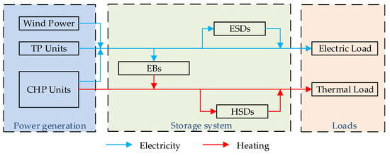
Figure 1.
The structure diagram of an electric-heat integrated energy system.
3. Powers Sources and Devices Models
As shown in Figure 1, the integrated energy system consists of three parts. The power generation sector consists of CHP units, TP units, and wind power units, which produce electricity and heat. Storage system includes HSDs, ESDs and EBs. The heat generated by an EB is partly supplied by direct heating and partly stored in a HSD. HSDs and ESDs are used for energy storage, mainly including batteries, storage tanks. The third part is loads, including thermal load and electrical load. In this paper, TP units, CHP units, HSDs, ESDs, and EBs are modeled separately. Modularization makes the model more universally applicable.
3.1. Conventional Thermal Power Units
3.1.1. Operation Costs Model
3.1.2. Constraints
Generation from the TP units is bounded by the following inequality constraints:
where and are the upper and lower limits of the TP unit , respectively.
At the same time, the units are constrained by the climbing speed:
where and are the maximum downward and upward climb speed of unit , respectively. is the interval per unit time.
3.2. CHP Units
3.2.1. Operation Costs Model
3.2.2. Constraints
Considering the general actual operation, CHP units in this model are steam extraction units without adjusting the extraction volume, that is, they are operated in the mode of the fixed thermoelectric ratio. The heating ratio constraint is as follows:
where is the electric heating rate of CHP unit .
Like TP units, the CHP units must meet the upper and lower limits of output constraint:
where and are the lower and upper limits of the CHP unit , respectively.
The same goes for the climbing speed constraint:
where and are the maximum downward and upward climb speed of CHP unit .
3.3. Heat Storage Devices
3.3.1. Operation Costs Model
3.3.2. Constraints
The capacity of HSDs is limited, and the rate of heat storage and heat release is also capped. Therefore, the specific constraint expression is as follows:
where is the stored heat capacity. is the total capacity of the device. and are the upper limit of the heat storage power and heat release power, respectively.
In actual operation, it is approximately believed that heat leakage loss power is proportional to heat storage. In addition, the HSD is generally required to be in an operating cycle, usually 1 day, and then it will be restored to the original heat storage. The specific constraint expression is as follows:
where is the heat leakage ratio.
It is also a constraint that a HSD cannot be operated both in heat storage and exothermic states. The specific constraints are as follows:
3.4. Electric Storage Devices
3.4.1. Operation Costs Model
3.4.2. Constraints
The constraint of ESD is similar to that of HSD. The capacity constraint, power storage and discharge constraint, and working condition constraint are mainly considered at the same time.
3.5. Electric Boilers
3.5.1. Operation Costs Model
The cost of the electric boiler is not taken into account, because it only uses the abandoned wind power for heating.
3.5.2. Constraints
The constraints of electric boiler mainly include the electric heat conversion ratio and upper limit of power consumption. Specific constraints are as follows:
where is the electric heat conversion ratio. It is usually equal to 1. is the electrical power of the electric boiler. is the thermal power provided by the device. is the maximum power.
4. Overall Optimal Scheduling Model
4.1. Objective Function
To achieve the maximum absorption of wind power and overall economical efficiency of the system, the objective function of the model comprehensively takes into consideration the minimum wind curtailment and the lowest total operating cost of TP units, CHP units, HSDs, and ESDs. The specific objective function is as follows:
where is the total number of optimized periods. is the number of wind turbines. is the wind curtailment power of wind turbine . is the cost penalty coefficient to ensure the overall economic efficiency of the system. , , , and are the quantities of CHP units, HSDs, ESDs, and TP units.
4.2. Constraints
In addition to the constraint conditions of the above models, the system electrical load balance and thermal load balance constraints should also be considered:
where is the electrical load at time . is the reserve at time . is the heat load. What is more, the network security constraints are as follows:
where is the power of branch at time . , are the limits of .
4.3. Solution Method
At present, there are many methods to solve optimization problems, such as the nature-inspired algorithm [20,21,22] or numerical algorithm [23,24]. The mixed integer programming is adopted in this article. The GLPK, which is a mature open source software package, is used to solve this mixed integer programming problem. It uses the method of proximity search, which has the capability of quickly improving the first MIP incumbents and improves the solution speed significantly [25].
5. Case Study
The system parameters, work scenarios, and other information of the case are shown in Table 1.

Table 1.
Case information.
As can be seen from Table 1, Fortran and GLPK are used to solve the example. Example data are from a provincial power grid, including two thermal power plants and two power storage plants. Thermal power plant A includes CHP units and HSDs. Power plant B includes CHP units, EBs and HSDs. The maximum capacity of the HSDs of the two thermal power plant is 300 and 200 , respectively. The maximum charge-discharge power of storage stations A and B is 25 MW and 20 MW, respectively. In the example, there are about 3000 regular variables and 1800 relaxation variables at one point in time, a total of about 5000 variables. Time granularity of 15 min is used, so there are 96 points in a day, a total of about 500,000 variables. Examples in this paper verify the practicability of this model from the perspective of four working conditions: ordinary operating conditions (condition 1), a small amount of wind abandoning conditions (condition 2), all-day wind curtailment conditions (condition 3), and conditions where the wind abandoning period is not long enough to fill HSDs (condition 4).
5.1. Ordinary Operating Conditions
The optimization scheduling result for condition 1 is shown in Figure 2.
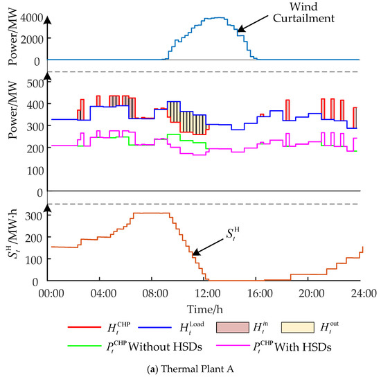
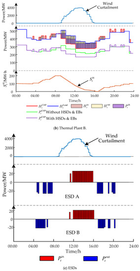
Figure 2.
The optimization scheduling result of condition 1.
As can be seen from Figure 2a,b, during the curtailment period, the electrical power output of CHP units of these two power plants decreased, leading to a decrease in heat output. Therefore, in order to meet the demand of heat load, HSDs releases heat to make up for the lack of heat output. Moreover, the capacity of HSDs is maximized. In addition, the electric boiler of plant B is also converted to heat during the wind curtailment period. Various resources are operated in a flexible way, thereby improving the absorption capacity of wind power effectively.
5.2. All-day Wind Curtailment Conditions
The optimization scheduling result for condition 2 is shown in Figure 3.
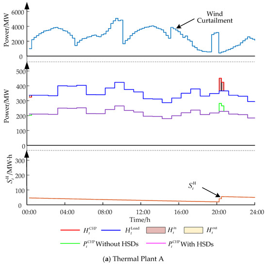
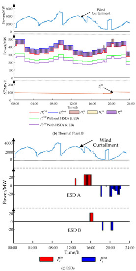
Figure 3.
The optimization scheduling result of condition 2.
In this working condition, it can be seen from Figure 3a,b that the two HSDs hardly work. This is because the electric boiler does not need to store heat for HSDs. Otherwise, according to the operating conditions of HSDs, heat will be released at the end of a cycle, resulting in the loss of energy. There is no need to pump steam to the unit for heat storage, too. Otherwise the unit will increase the electrical output, further aggravating the wind curtailment. The coordinated operation of this model under this condition can alleviate the curtailment of wind and also take into account the economic efficiency of system operation.
5.3. A Small Amount of Wind Curtailment Conditions
The optimization scheduling result for condition 3 is shown in Figure 4.
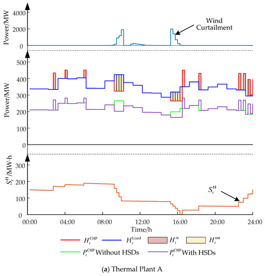
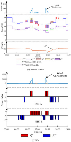
Figure 4.
The optimization scheduling result of condition 3.
It can be seen from Figure 4 that in this operating condition, the unit’s electric output also decreases. Electricity is also stored at two storage plants. The HSD capacity remains because the volume of wind curtailment is small and the wind curtailment period is too short. Under this condition, the model can solve the problem of wind abandoning well.
5.4. Conditions Where the Wind Curtailment Period Is Not Long Enough to Fill HSDs
The optimization scheduling result for condition 4 is shown in Figure 5.
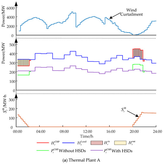
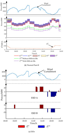
Figure 5.
The optimization scheduling result of condition 4.
Under this working condition, since the wind curtailment period is very short, the heat storage tank cannot be full, and the capacity of HSDs is insufficient. However, if the heat storage power of HSDs is increased, the heat storage capacity can be theoretically improved, thus the utilization effect can be enhanced.
5.5. Case Study Conclusions
The enhancement of wind power accommodation in four working conditions is shown in Table 2.
Table 2.
Wind power accommodation enhancement under four conditions.
As can be seen from Table 2, under the four working conditions, the increased accommodation rate did not increase significantly due to the large amount of original wind curtailment that exceeded the absorption limit of the system. However, the increased consumption of curtailment power has a major improvement, among which the maximum is 2441.07 in working condition 4. In working condition 3, the utilization rate of heat storage and energy storage device is low due to the low volume and the short period of wind curtailment, resulting in a relatively low amount of increased consumption of curtailment power. However, its increased accommodation rate is the highest, at 20.38%, which indicates that the effect of wind abandoning consumption lifting under this working condition is also relatively obvious. The four examples can prove that the model in this paper can satisfy various working conditions under actual operation condition, and the joint coordinated dispatching of various resources can greatly improve system flexibility and increase the absorption capacity of wind power. At the same time, it can be concluded that the configuration of heat storage device should consider not only the capacity of HSDs, but also the heat storage power of HSDs. In a word, the higher the heat storage power, the stronger its ability to adapt to various working conditions and the more applicable it is.
6. Conclusions
The key to improving the accommodation of wind power is to enhance the power system regulation ability under different working conditions and to improve the flexibility of that power system. In this paper, the coupling relationship between the power system and thermal system is analyzed. The electric–thermal integrated energy system is constructed. By using HSD and EB, the rigid constraint of "FLT" is decoupled, and the adjustment ability of CHP unit is improved. The fluctuation and intermittency of the output of renewable energy in the power system and the peak-valley characteristics of the power load are further stabilized by the ESD. Finally, a day-ahead energy storage and heat storage joint optimal scheduling model considering flexibility is established. Each power supply and device is modeled separately, which enables universal applicability. The objective function is the minimum cost and wind curtailment. Various practical situations are taken into account as constraints. The actual data of a provincial power grid in China are taken as an example, and the changes of the system operation before and after adding heat storage and energy storage are simulated to analyze four different working conditions. The results show that this model not only gives consideration to economic efficiency under different working conditions, but also coordinates and schedules various resources, effectively improving the flexibility of system and enhancing the absorption capacity of wind power.
Author Contributions
All of the authors have contributed to this research. Conceptualization, Y.Z.; methodology, Y.Z., F.X. and P.Z.; software, Y.Z.; writing—original draft preparation, P.Z.; writing—review and editing, Y.Z. and P.Z.; project administration, F.X.; supervision, D.C. and W.G.; data curation, X.C.; funding acquisition, B.G. All authors have read and agreed to the published version of the manuscript.
Funding
This research was funded by the State Grid Liaoning Electric Power Co., Ltd. Technology Project (NO. SGTYHT / 17-JS-199).
Acknowledgments
Thanks to my dear friends, Shengkai Guo, Pengxiang Huang, Yaya Zhang, and Yu Wang, for giving me valuable suggestions.
Conflicts of Interest
The authors declare no conflict of interest.
Appendix A
Table A1.
Table of full names and acronyms.
Table A1.
Table of full names and acronyms.
| Full Name | Acronym |
|---|---|
| Combined heat and power | CHP |
| Following the thermal load | FTL |
| Thermal power | TP |
| Heat storage device | HSD |
| Electric boiler | EB |
| Energy storage device | ESD |
References
- Bai, J.H.; Xin, S.X.; Liu, X.; Zheng, K. Roadmap of Realizing the High Penetration Renewable Energy in China. Proc. CSEE 2015, 35, 3699–3705. [Google Scholar] [CrossRef]
- Chen, X.; Kang, C.; O’Malley, M.; Xia, Q.; Bai, J.; Chun, L.; Sun, R.; Wang, W.; Li, H. Increasing the flexibility of combined heat and power for wind power integration in China: Modeling and implications. IEEE Trans. Power Syst. 2015, 30, 1848–1857. [Google Scholar] [CrossRef]
- Wu, Y.T.; Fu, L.; Zhang, S.G.; Tang, D.K. Study On A Novel Co-operated Heat and Power System for Improving Energy Efficiency and Flexibility of Cogeneration Plants. Appl. Therm. Eng. 2019, 163, 1–13. [Google Scholar] [CrossRef]
- Luo, Y.H.; Yin, Z.X.; Yang, D.S.; Zhou, B.W. A New Wind Power Accommodation Strategy for Combined Heat and Power System Based on Bi-Directional Conversion. Energies 2019, 12, 2458. [Google Scholar] [CrossRef]
- Lin, C.H.; Wu, W.C.; Zhang, B.M.; Sun, Y. Decentralized Solution for Combined Heat and Power Dispatch Through Benders Decomposition. IEEE Trans. Sustain. Energy 2017, 8, 1361–1372. [Google Scholar] [CrossRef]
- Shin, D.U.; Ryu, S.R.; Kim, K.W. Simultaneous Heating and Cooling System with Thermal Storage Tanks Considering Energy Efficiency and Operation Method of The System. Energy Build. 2019, 20, 1–14. [Google Scholar] [CrossRef]
- Lesko, M.; Bujalski, W.; Futyma, K. Operational Optimization in District Heating Systems with the Use of Thermal Energy Storage. Energy 2018, 165, 902–915. [Google Scholar] [CrossRef]
- Huo, D.; Wei, W.; Simon, L.B. Optimisation for Interconnected Energy Hub System with Combined Ground Source Heat Pump and Borehole Thermal Storage. Front. Energy 2018, 12, 529–539. [Google Scholar] [CrossRef]
- Lv, Q.; Chen, T.Y.; Wang, H.X.; Yu, T.; Li, Q.; Tang, W. Analysis on Peak-load Regulation Ability of Cogeneration Unit with Heat Accumulator. Autom. Electr. Power Syst. 2014, 38, 34–41. [Google Scholar] [CrossRef]
- Lv, Q.; Chen, T.Y.; Wang, H.X.; Li, L.; Lv, Y.; Li, W.D. Combined Heat and Power Dispatch Model for Power System With Heat Accumulator. Electr. Power Autom. Equip. 2014, 34, 79–85. [Google Scholar] [CrossRef]
- Xu, F.; Min, Y.; Chen, L.; Chen, Q.; Hu, W.; Zhang, W.L.; Wang, X.H.; Hou, Y.H. Combined Electricity-Heat Operation System Containing Large Capacity Thermal Energy Storage. Proc. CSEE 2014, 34, 5063–5072. [Google Scholar] [CrossRef]
- Ge, W.C.; Gao, M.L.; Zhang, Y.J.; Li, J.; Che, X.T.; Liu, Y.Y. Optimal Economic Dispatch of Integrated Energy System Based on Electric Boiler for Wind Power Accommodation. South. Power Syst. Technol. 2019, 13, 59–66. [Google Scholar] [CrossRef]
- Meibom, P.; Kiviluoma, J.; Barth, R.; Brand, H.; Weber, C.; Larsen, H.V. Value of Electric Heat Boilers and Heat Pumps for Wind Power Integration. Wind Energy 2010, 10, 321–337. [Google Scholar] [CrossRef]
- Lv, Q.; Jang, H.; Chen, T.Y.; Wang, H.X.; Lv, Y.; Li, W.D. Wind Power Accommodation by Combined Heat and Power Plant with Electric Boiler and Its National Economic Evaluation. Autom. Electr. Power Syst. 2014, 38, 6–12. [Google Scholar] [CrossRef]
- Yuan, X.M.; Cheng, S.J.; Wen, J.Y. Prospects Analysis of Energy Storage Application in Grid Integration of Large-scale Wind Power. Autom. Electr. Power Syst. 2013, 37, 14–18. [Google Scholar] [CrossRef]
- Shi, J.; Wang, L.H.; Lee, W.J.; Cheng, X.G.; Zong, X.J. Hybrid Energy Storage System (HESS) Optimization Enabling Very Short-term Wind Power Generation Scheduling Based On Output Feature Extraction. Appl. Energy 2019, 256, 1–10. [Google Scholar] [CrossRef]
- Wu, W.; Lin, B.Q. Application Value of Energy Storage In Power Grid: A Special Case of China Electricity Market. Energy 2018, 165, 1191–1199. [Google Scholar] [CrossRef]
- Kia, M.; Nazar, M.S.; Sepasian, M.S.; Heidari, A.; Siano, P. Optimal Day Ahead Scheduling of Combined Heat and Power Units with Electrical and Thermal Storage Considering Security Constraint of Power System. Energy 2017, 120, 241–252. [Google Scholar] [CrossRef]
- Kose, F.; Kaya, M.N. Wind-Hydro Pumped Storage Power Stations to Meet the Energy Demands of Irrigation: Feasibility, Optimal Design and Simulation of a System. J. Chin. Soc. Mech. Eng. 2018, 39, 223–232. [Google Scholar]
- Wu, X.S.; Zhang, B.H.; Yuan, X.M.; Li, G.W.; Luo, G.; Zhou, Y. Solutions to Unit Commitment Problems in Power Systems With Wind Farms Using Advanced Quantum-inspired Binary PSO. Proc. CSEE 2013, 33, 45–52. [Google Scholar] [CrossRef]
- Tian, K. Unit Commitment Model and Solution in the Hybrid Power System Based on Chaos Embedded Particle Swarm Optimization-Scenario Reduction Algorithms. Power Syst. Technol. 2013, 37, 1019–1024. [Google Scholar] [CrossRef]
- Hussain, S.; Al-Hitmi, M.; Khaliq, S.; Hussain, A.; Saqib, M.A. Implementation and Comparison of Particle swarm Optimization and Genetic Algorithm Techniques In Combined Economic Emission Dispatch of An Independent Power Plant. Energies 2019, 12, 2037. [Google Scholar] [CrossRef]
- Li, Q.; Zhang, L.D.; Yin, M.H.; Zhang, X.L.; Zou, Y. Fuzzy decision-making based unit commitment of power grid integrated with wind farms. Power Syst. Technol. 2013, 37, 2480–2485. [Google Scholar] [CrossRef]
- Guan, X.H.; Zhai, Q.Z.; Gao, F. Short-term Hydrothermal Scheduling Using Mixed-integer Linear Programming. Proc. CSEE 2009, 29, 82–88. [Google Scholar] [CrossRef]
- Fischetti, M.; Monaci, M. Proximity Search for 0–1 Mixed-integer Convex Programming. J. Heuristics 2014, 20, 709–731. [Google Scholar] [CrossRef]


© 2020 by the authors. Licensee MDPI, Basel, Switzerland. This article is an open access article distributed under the terms and conditions of the Creative Commons Attribution (CC BY) license (http://creativecommons.org/licenses/by/4.0/).