Article

Improving Fuel Economy of Spark Ignition Engines Applying the Combined Method of Power Regulation

1
Department of Engines and Thermal Engineering, Faculty of Faculty of Automotive and Mechanical Engineering, National Transport University, Mykhaila Omelianovycha-Pavlenka Str. 1, 01010 Kyiv, Ukraine
2
Department of Ecology and Safety of Vital Functions, Faculty of Faculty of Automotive and Mechanical Engineering, National Transport University, Mykhaila Omelianovycha-Pavlenka Str. 1, 01010 Kyiv, Ukraine
3
Institute of Mechanical Science, Vilnius Gediminas Technical University, J. Basanavičiaus Str. 28, LT-03224 Vilnius, Lithuania
4
Department of Automobile Engineering, Vilnius Gediminas Technical University, J. Basanavičiaus Str. 28, LT-03224 Vilnius, Lithuania
5
Department of Automobile Transport Engineering, Vilnius College of Technologies and Design, Antakalnio St. 54, LT-10303 Vilnius, Lithuania
6
Department of Technical Exploitation and Service of Cars, Kharkiv National Automobile and Highway University (KhNAHU), Yaroslava Mudrogo St, 25, 61000 Kharkiv, Ukraine
*
Author to whom correspondence should be addressed.
Energies 2020, 13(5), 1076; https://doi.org/10.3390/en13051076
Submission received: 7 January 2020 / Revised: 19 February 2020 / Accepted: 23 February 2020 / Published: 1 March 2020
(This article belongs to the Special Issue Advances in Spark-Ignition Engines)

Abstract

:
One of the disadvantages of spark ignition engines, whose power is regulated by throttling, is the increased fuel consumption at low loads and when the engine is idle. The combined method of engine power regulation by switching off the cylinder group and throttling working cylinders is one of the effective ways to improve fuel economy in the above-mentioned modes. This article presents the research results of the combined method of engine power regulation which can be realized by minor structural changes in operating conditions. The method implies the following: at low loads and at idle speed of the engine. Fuel supply to the group of cylinders is switched off with the simultaneous increase of the cyclic fuel supply in the working cylinders. The adequacy of the calculated results has been checked by the indication of operating processes in switched off and working cylinders. The research results of a six-cylinder spark ignition engine with the distributed gasoline injection using the combined power regulation system have been shown. The angles of opening the throttle which provides a non-shock transition from the operation with all cylinders to the operation with the cylinder group switched off have been determined.

1. Introduction

Many factors influence fuel economy (FE) and the amount of pollution (HS) in the exhaust gas (EG) of cars with internal combustion engines (ICE). Research carried out on automobile engines shows that the modes of car motion have great influence on these indicators.
The movement of a car, in large cities in particular, is accompanied by complicated operating modes of the engine: acceleration, deceleration, constant and unstable modes, and modes of independent and forced idling. In this case, most of the time cars move at a low speed, with the engine running at low loads and at idle speed.
Operating modes of automobile engines under operating conditions have been investigated in many papers. At low speed and low load, high heat transfer and combustion losses occur, directly affecting engine operating conditions [1]. In most cases, these actual engine operating conditions are not reflected in standardized driving cycles and, sometimes, summaries of experimentally-derived cycles are also used to evaluate traffic jams [2]. Design changes, such as ceramic-coated engines, have also been used to reduce heat loss, which, when used in combination with biodiesel as fuel, have shown optimum engine operating conditions [3]. This effect is also noticeable when using triglyceride-based biodiesel as fuel [4]. Hydroxyl gas can also be used as an indicator to improve engine natural conditions, resulting in higher thermal efficiency and improved exhaust emissions [5]. The possible use of biobutanol as another source of biofuels and similar trends in engine operating conditions due to its higher oxidative stability [6] as a spark ignition [7], as a compression ignition engines [8]. It is also known that the use of alcohol additives in petrol improves its properties and achieves an ecological effect [9]. The EGR system shows a different reduction in cycle pressure [10] which is noticeable when operating small engines [11]. Studies [12,13,14,15] shows that the basic operating modes of both freight and passenger vehicles moving in cities are part speed and loading modes. They involve acceleration, steady mode, and active and forced idling while driving and braking the car. Most of the time the vehicular engines run the open throttle or with a fuel supply of not more than 50%. The time of operation with a full load, when supplying the fuel is close to the maximum, is not more than 30%. This is particularly emphasized in the context of the development of smart cities, where freight delivery can be modeled on special robotic vehicles [12]. It is important to emphasize that the use of such transport is specialized and more tailored to individual customers, with a higher standardized freight flow due to the limited engine described above and the rail network used [13]. Nevertheless, the combined approach to passenger and freight transport is widely developed [14]. This option offers great advantages especially when considering ecological aspects [15].
In general, it can be concluded that under operating conditions, the main motor vehicle modes of operation are part load speed modes and idling modes. In these modes, the fuel economy of spark ignition engines significantly deteriorates which is one of the main disadvantages of these engines. The reason for this deterioration is the decrease of the indicated efficiency of the actual cycle. It is due to the increase in the relative amount of EG and the deterioration of mixing and combustion conditions [16,17,18,19,20,21,22,23]. Double sparking can cause early release of heat and reduce the knocking effect [16]. Spark shortening phenomena have been observed during the extension of the spark discharge period [21]. What is especially important with the dual fuel system with biogas and ethanol fuel is the reduction in the knocking effect at full engine load [17]. Additionally, exhaust residuals have a direct influence on the combustion process [18]. With the use of hydrogen as an additive in the fuel it is possible to extend the combustion limits of the lean [19]. Another way is to use the thermal efficiency optimization strategy in the case of lean combustion, which also helps to combat combustion variations [20]. The deterioration of mixing and combustion conditions was also addressed using a multi hole injector [22], and in a wide range of engine speed [23]. In addition, the degree of repeatability of successive cycles is increased. Mechanical losses grow which consist of friction losses and pump losses. These losses significantly increase with decreasing load. This is due to the rise of dilution in the inlet line and when throttling can reach 50% of the total mechanical loss [24,25]. Relative friction losses also increase significantly when the load changes. They do not depend on the rotational speed of the crankshaft, which has been proved in many previous papers. This was confirmed by both machine learning model simulations [26], using artificial neural network modeling [27], a zero-dimensional cylinder pressure model [28], the crankshaft rotation measurement experimental method [29], using the crankshaft dynamics research method [30], a comparison of frictional losses research [31], and both by studying the influence of initial starting conditions on the above factors [32].
One of the most effective methods to improve fuel efficiency in the above-mentioned modes is switching off the group of cylinders with the change of the gas exchange system. This method is widely used in modern engines. In fact, it is the combined method of power regulation as it includes switching off the cylinder group and throttling the working cylinders. The homogeneity of the flammable mixture influences the efficiency of disconnecting the cylinders [33]. This is noticeable especially with direct injection spark engines [34]. This also allows for an ecological effect [35] and the fuel economy effect [36], and the issue of tribological performance of piston compression ring and connecting rod bearing is also addressed [37]. According to Ihlemann at al. this is the technology of the future [38].
The use of this method requires significant changes in the design of the engine and is realized in the production process.
The aim of this work is improving fuel economy of spark ignition engines applying the combined method of power regulation.
The combined method, in which the system of gas exchange does not change, has been studied. The power of the engine at small external loads is obtained by switching off the cylinder group when the second group of cylinders works with a large opening of the throttle and higher efficiency. The group of cylinders is switched off by disabling the fuel supply to these cylinders. The position of the throttle valve and the cyclic supply of fuel in the working cylinders is simultaneously increased. It ensures equal power for the operation with all cylinders and with the cylinder group switched off.

2. Theoretical Substantiation of Possible Improvement of Fuel Economy

One of the main reasons for the significant deterioration of fuel economy of spark ignition engines in low load and idling modes is a decrease of the indicated efficiency of the engine and an increase of mechanical losses. Under the combined power regulation method, if the indicated efficiency increases and the mechanical losses decrease, as compared to throttle all cylinders, fuel economy of spark ignition engines is improved.
The comparison has been made for a six-cylinder engine with a distributed gasoline injection system and feedback [35,39]. The dependency of the indicated efficiency on the average effective pressure, which is proportional to the external load, has been determined taking into account the nature of the combustion, the duration of the combustion phases, and the effect of residual gas [10,34,40].
The dependencies of the indicated efficiency “ηi” on the average effective pressure “pe” from zero to an average effective pressure of 0.35 MPa are shown in Figure 1. It implies throttling and switching off three cylinders at loads where the operation of three and six cylinders is possible [39].
As it can be seen from the shown dependencies, the value of the indicated efficiency when three cylinders are switched off, ηi varies from 0.306 (in idling mode) to 0.345 (before the enrichment of the mixture). When throttling, the indicated efficiency ηi th at this load varies within the range of 0.26, ..., 0.32. Thus, the transition from throttling fuel-air mixture to the combined method at idling modes and low loads by switching off the cylinder group and throttling working cylinders can increase the indicated efficiency of a gasoline engine with an electronic control and a feedback injection system by 13.7–7.8%. With an average effective pressure of more than 0.325 MPa, it is advisable to throttle all cylinders.
The effect of the combined method of power regulation on mechanical losses has been estimated at the same values of the average effective pressure pe.
The average effective pressure pe required for vehicle motion when throttling and switching off “k” cylinders of the engine with “i” cylinders has been determined by the dependencies:
p e   t h   =   p i   t h     p m   t h ,
p e d = i k i p i d p m d
where pi th and pid are the average indicated pressure when throttling and switching off the cylinders; pm th and pmd are the average pressure of mechanical losses using the combined method of power regulation.
It is known that, during throttling, the average mechanical loss pressure pm th includes the average pressure pt th used for friction, pressure pg th for the gas exchange process, and pressure pd th for the camshaft drive, auxiliary equipment and ventilation losses. That is:
p m t h   =   p t t h   +   p g t h   +   p d t h .
When “k” cylinders of an “i”-cylinder engine are switched off, the average mechanical loss pressure pm d includes the average pressure p/t d used for friction in the working “i-k” cylinders and pressure p//t d in “k” switched off cylinders, the loss pressure pg d for gas exchange process in the “i-k” working cylinders and p//g d in “k” switched off cylinders, the pressure pd d for the camshaft drive, auxiliary equipment, and ventilation losses, as well as the average pressure pq d for heat losses in the switched off “k” cylinders is:
p m d = i k i p t d + k i p t d + i k i p g d + k i p g d + p d d + k i p q d
Components of mechanical losses have been calculated using theoretical and empirical dependencies. Some of them have been partially identified experimentally.
Using these data, the dependence of the engine performance on the average effective pressure has been shown when throttling (Figure 2) and switching off the three cylinders of the engine (Figure 3) for n = 1800 rpm.
As can be seen from the comparison of the dependencies of pmd(peth) (Figure 3) and pmth (ped) (Figure 2), the same pe, mechanical losses when the cylinders are switched off are smaller compared with the throttling. For pe = 0 it has been obtained: pmth = 0.153 MPa, pmd = 0.145 MPa, and for pe = 0.35 MPa: pmth = 0.138 MPa, pmd = 0.109 MPa. Thus, with the transition to the combined method of power regulation of gasoline engine, fuel economy improvements can be expected as a result of reducing the internal losses.
Using the method of the volume balance, a mathematical model of the engine operating process with cylinders switched off has been developed [23,41,42]. The adequacy of the calculated results has been checked by the indication of operating processes in switched-off and working cylinders.
The mathematical model to evaluate vehicle fuel consumption and pollution emission in a driving cycle using the combined method of power regulation has been developed in scientific papers. Fuel economy modeling is closely linked to vehicle weight, which is increasing by 4.7% annually on cars sold in the Chinese market since 2015 [43], therefore, modeling of exhaust emissions and energy sustainability is performed [44], which is heavily dependent on the interests of energy distribution companies [45]. The assessment of pollutions emissions is related to the promotion of green vehicle use [46], both with an efficient quantified risk assessment [47] resulting from the use of floating vehicle data [48] and on the optimization of control strategy to reduce fuel consumption [49], fuel consumption software (PΔP) [50], interactions between vehicles and pedestrians [51], and vehicle routing problems [52]. Ehsani et al. provides a clear model for the dependence of fuel consumption on carbon dioxide emissions [53]. Applying such a model would reduce freight transport exhaust and improve fuel economy [54]. However, such links are very much dependent on traffic jams if we look at the urban situation [55].
The theoretical analysis shows that the use of the combined power regulation method will improve fuel economy of spark ignition engines compared with throttling in partial load modes and idling modes.

3. Materials and Methodology

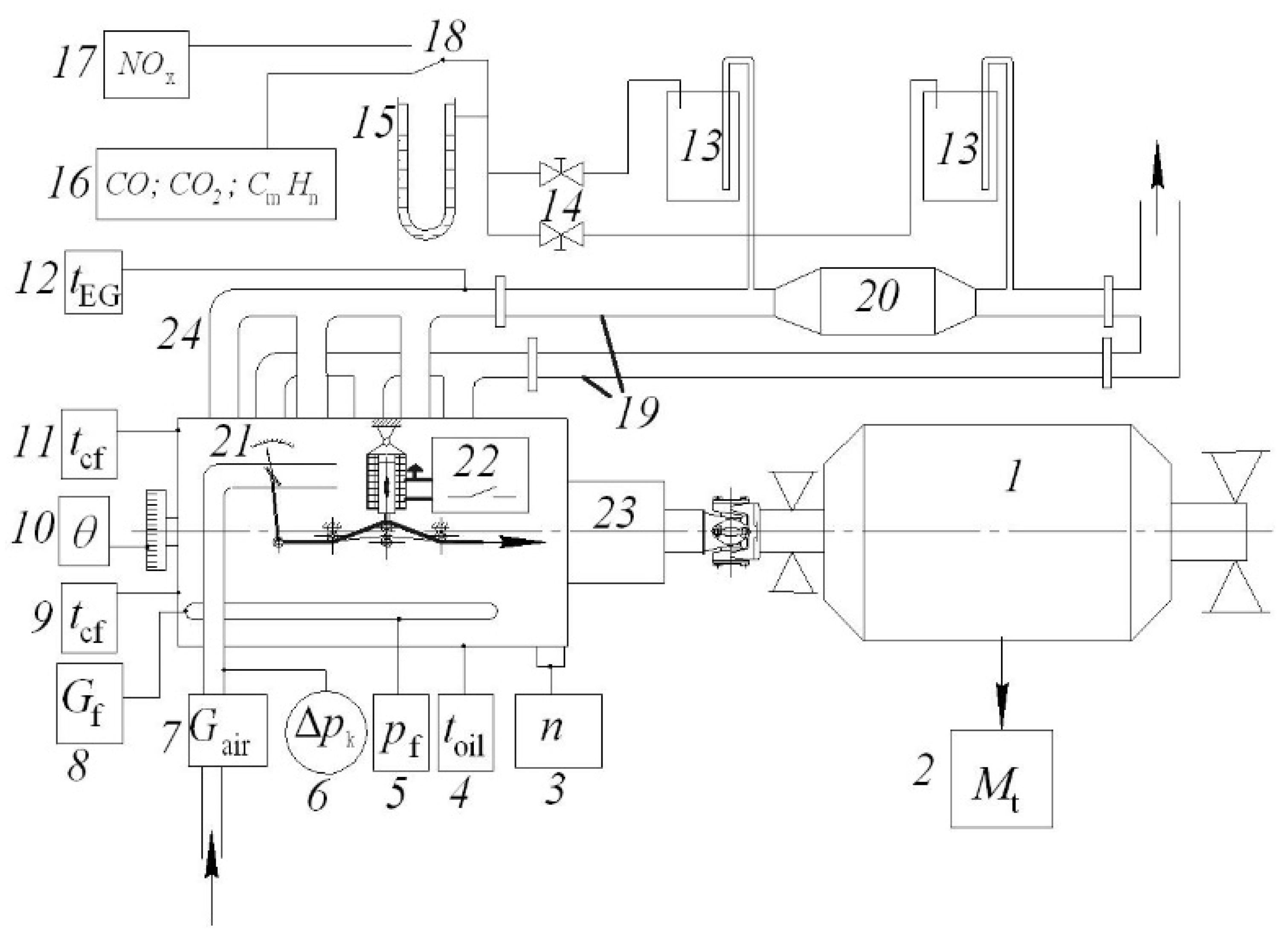
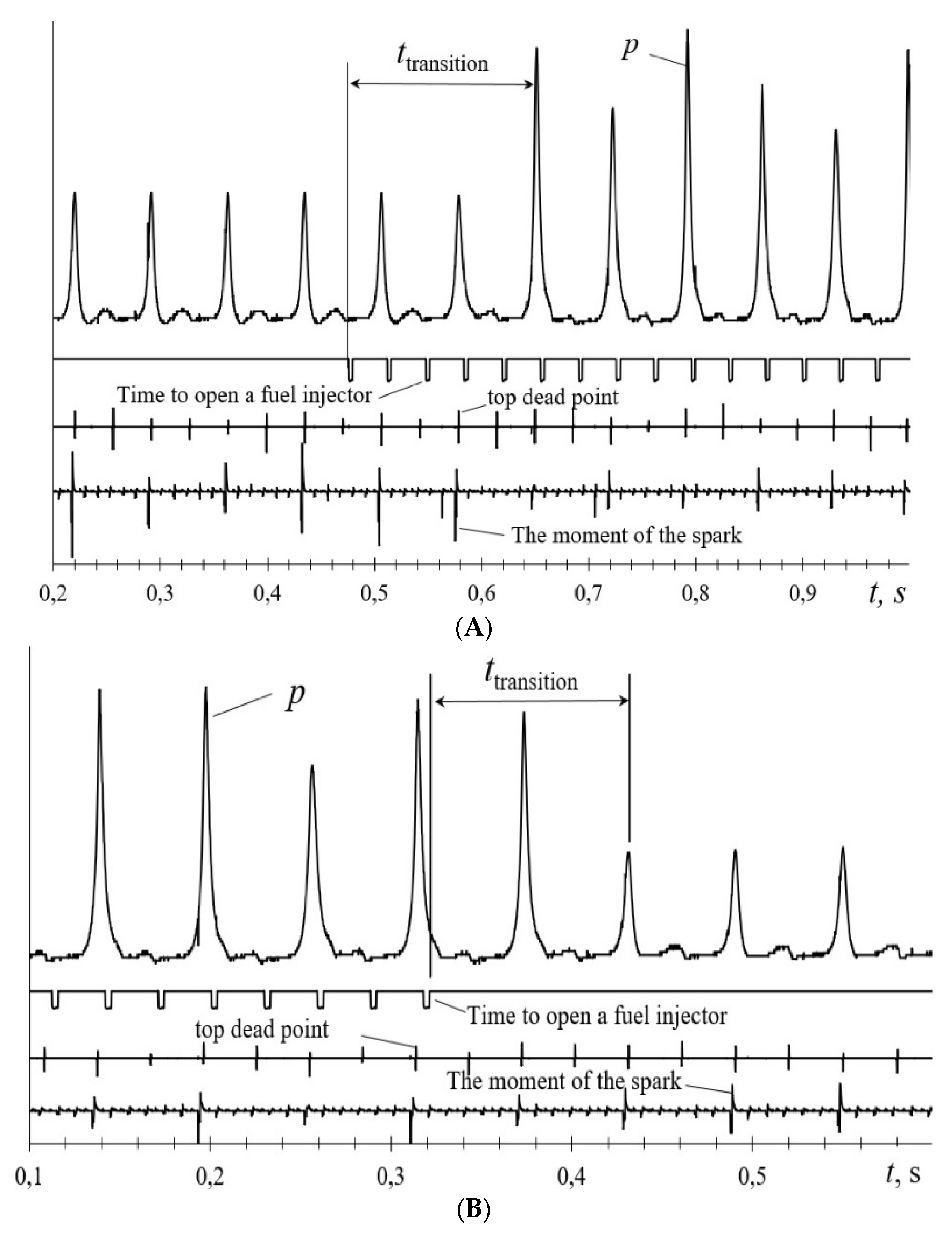
3.1. Working out the Fuel Supply System

The experimental model of a fuel supply system to implement the combined power regulation method is based on a Bosch “Motronik ML 4.1” (“Robert Bosch GmbH”, Gerlingen, Germany) fuel supply system in the mechanical drive throttle. The scheme of the experimental system is shown in Figure 4 [20]. The main algorithm of its operation implies the termination of the fuel supply to the switched-off cylinders without changing the gas exchange in small loads and idling modes. The engine is equipped with the new system without structural changes in the electronic control unit of the injection system and engine ignition. It can, therefore, be installed on vehicles in operation. This system of power regulation has five patents in the Ukraine for utility models [35].
The system works as follows: an electromagnet (31), whose operation is controlled by the electronic control unit of the nozzles (11), is added to the fuel supply system of the engine with a mechanical cable throttle actuator. The core of the electromagnet is connected to the tension roller (27) through which the control cable passes to the throttle (28).
With partial loads and idling mode running, the electric current of the electromagnet (30) is activated by the command of the electronic control unit (11) to the coil relay switching the electromagnet. When the electromagnet (31) switches on, its core moves the tension roller (27) to a predetermined value Δl. As a result of it the opening angle of the throttle (17) is changed to a predetermined value according to the engine operation with the cylinders switched off.
At the same time, the electronic control unit of the nozzles (11) receives the signals from the rotational speed sensors (24) and the position of the throttle (16) disables the nozzle assembly (10) by re-directing the electric current to the ballast resistance (9). As a result, the engine does not enter the emergency operating mode.
With an increase in the engine load to a mode where the operation with a subset of cylinders becomes less economical with respect to fuel consumption than with all cylinders, at the same crankshaft rotation frequency, the electronic control unit of the nozzles (11), according to the signal of the position sensor of the throttle valve (16), connects the block of the inactive nozzles (10) to the fuel supply system. At the same time, electromagnet (31) controls the tension roller (27). The angle of opening the throttle (17) changes to the value corresponding to the engine operation with all cylinders.
When reducing the load of the engine or during transition to the idling mode, when the engine is more efficient at switching off the cylinder group, there is a reverse process of disconnecting the block of injectors and the inclusion in the chain of the ballast resistance. The angle of opening the throttle changes simultaneously to the value corresponding to the engine operation for part of cylinders.
The cold start of the engine and its heating occurs due to the engine operation with all cylinders. This is provided by the air temperature sensor (19) and the temperature sensor of the engine (22), the signal of which comes to the electronic control unit of the nozzles (11). The group of switching off cylinders can also be changed.

3.2. Working out the Experimental Installation

For experimental research, an experimental installation has been developed consisting of a six-cylinder inline Opel C30 LE engine. The technical characteristic, given in Table 1.
The engine has been installed on a universal brake stand SGEU-100 with an electric brake AKB-92-4, the power of 100 kW and a maximum rotation 3000 rpm. The installation enables testing the engine in wide limits of external loads. The schematic diagram of the experimental installation with measuring devices is shown in Figure 5.
The experimental prototype of the fuel supply system to implement the combined power regulation method is installed on the engine (Figure 6).
Separate exhaust pipes for a group of three cylinders that constantly work and a group of switched-off cylinders have been installed on the engine. In the outlet pipeline of a continuously working cylinder group, a three-component catalytic converter manufactured by the Arvin Tefh company (Madison, IN, USA) has been installed on the 1.5 L engine. This is only the working cylinder group.
Measurement equipment accuracy is presented in Table 2.

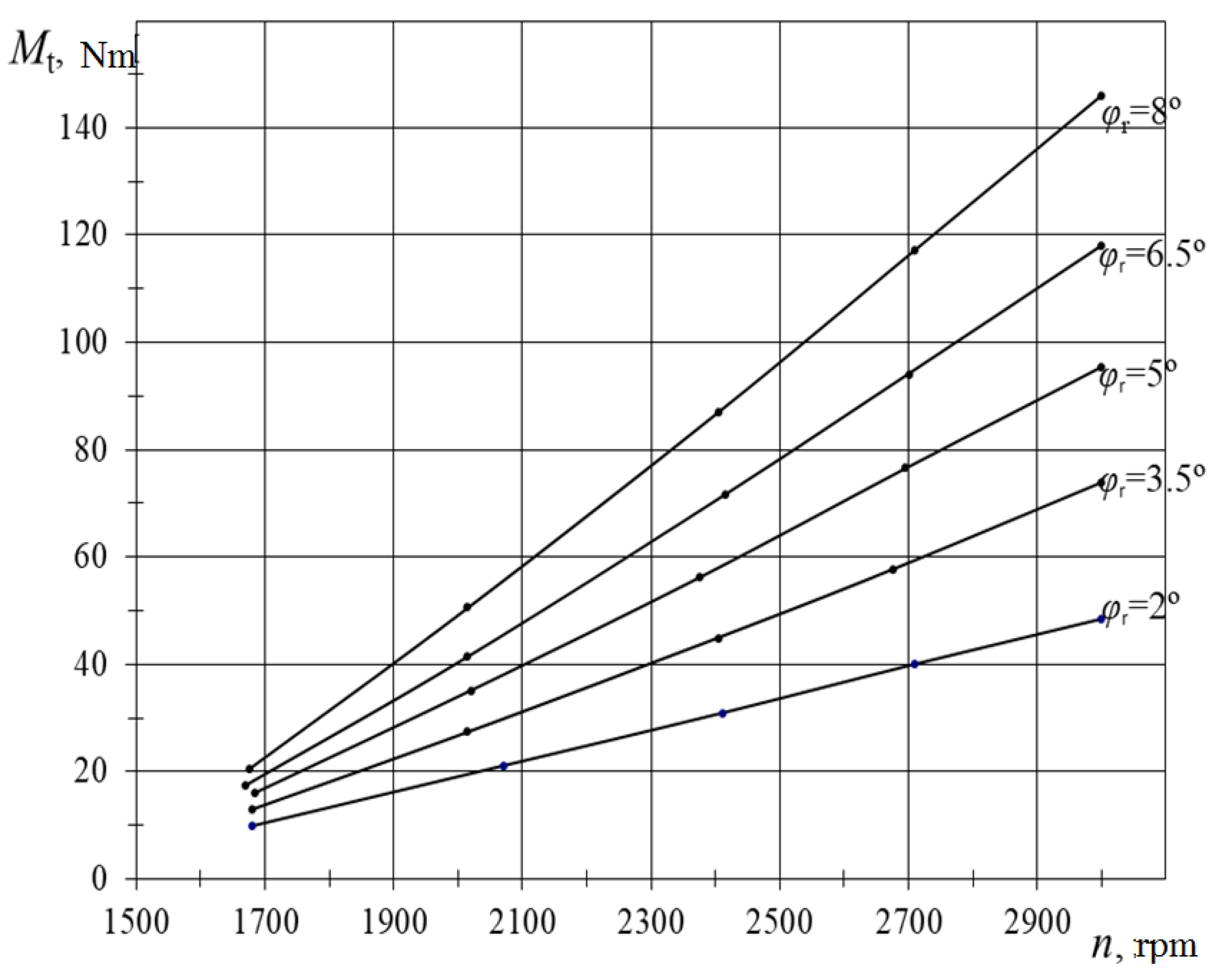
4. Results and Discussion

The efficiency of the combined method as for fuel economy improvement has been assessed on the load characteristics in the load area, where the engine can operate with throttling six cylinders or with throttling three cylinders and three cylinders are switched off.
Figure 7 shows the load characteristics of the engine for its operation with three and six cylinders at n = 2600 rpm. Hence, it is evident that throughout all loads from idling modes and before the operation of the enrichment device, the stoichiometric composition of the fuel and air mixture is maintained, regardless of the number of working cylinders (λ = 1.0). When three cylinders are switched off in this high-speed mode, the maximum torque of the engine Mt decreases from 191 Nm to 84 Nm. For loads up to 65 Nm for three-cylinder engine performance there is an improvement in fuel economy compared to the operation with all cylinders, hourly Gf and brake specific fuel consumption (BSFC) is reduced by an average of 13%. At the same time, load reduction fuel economy improves. In idling modes for fuelling a three-cylinder engine, the fuel economy is about 19%. When the load Mt = 65 Nm, fuel consumption for the engine running on six and three cylinders is the same. At a larger load the engine operation with a group of switched off cylinders becomes less economical and therefore inappropriate. The operation of the engine with three cylinders compared to the operation with six cylinders is characterized by a larger opening of the throttle ϕdr, the lower thinning of Δpk, and larger volumetric efficiency of engine ηv, with practically the same air flow Gair.
When determining the load characteristics, the concentration of pollutions in exhaust gases of the engine has been measured before and after the converter. The obtained characteristics are shown in Figure 8.
An analysis of the environmental performance of the engine indicates a significant increase in nitrogen oxide NOx concentration when the engine runs on three cylinders compared with the engine running on six cylinders. When applying a three-component catalytic converter, the NOx concentration in both cases is significantly reduced to practically the same level. Similar results were obtained by Ozhan et al. after years of research using multilevel flow modeling [56]. Concentrations of carbon oxide CO, carbon dioxide CO2, and hydrocarbons HC in the operation of the engine with catalytic converters with different numbers of working cylinders are also practically the same.
The improvement in fuel economy for the operation with three cylinders has been obtained in other high-speed modes (Figure 9); the engine load was low (Mt = 40 Nm).
One of the main issues when adjusting the power of a gasoline engine by the combined method is to determine the rules of changing the position of the throttle valve when switching off and switching on the cylinder group. It provides a non-shock process of changing the number of working cylinders. To establish such a pattern, an experimentally determined series of load characteristics with the measurement of the engine torque, fuel consumption, and the position of the throttle valve for each speed mode, a load mode has been established. The results obtained are similar to those of Fleischman et al. bus tests, where the test was conducted under roadworthiness test conditions [57]. When it is exceeded, the operation of the engine with the switched-off cylinders is inappropriate in terms of fuel economy.
Figure 10 shows the experimental dependencies of the hourly flow of petrol Gp and the opening angle of the throttle valve ϕdr on the torque Mt of a six-cylinder Opel C30 LE petrol engine with a distributed injection system with a feedback with six and three cylinders at different speeds.
The dependencies show that when the group of cylinders is switched off and on, the position of the throttle valve does not change, and the torque will vary several times.
As can be seen from the characteristics shown, the same torque when switching off and on a group of cylinders can be obtained at different ratios of the opening angle of the throttle valve.
The analysis of experimentally determined characteristics (Figure 11) shows that for the engine in all high-speed modes to obtain a practically unbreakable transition from the operation with three cylinders to the operation with six cylinders, and vice versa, it is advisable to do the transition at a torque moment Mt close to 50 Nm and a ratio of the opening angle of the throttle valve of 1.75.
One of the main factors influencing the efficiency of the combined method for power regulation of a multi-cylinder petrol engine is the duration of switching off and on the cylinder group.
The exact duration values of the transition process when switching off and on the cylinder group have been determined by indicating the operating process in the cylinder. Figure 11 shows a fragment of oscillograms of the operating process in cylinder A, when fuel is supplied to the cylinder; B, when fuel is not supplied to the cylinder. Oscillograms have been recorded at a load of Mt = 50 Nm, (n = 2000 rpm).
From these fragments it can be seen that both switching on and switching off the cylinder have a transition process in 1–2 operating cycles and almost without gradual increase or decrease of the indicated pressure. When the cylinders are switched on (Figure 11A), the full operating cycle has been restored for approximately 0.15 s. At the same time, the maximum combustion pressure, starting from the second cycle, remains unchanged during all subsequent cycles within the uneven values of cylinder operation.
A similar process occurs with switching off the cylinders (Figure 11B). After the fuel injector stops working, the first operating cycle is without breaking the parameters of the operating process. The next one is without the combustion process. The duration of the transition process when switching off the cylinders lasts for about 0.1 s.
To prove a short-term nature of the transition process, when cylinders are turned on and off, the oscillograms of the operating process during acceleration and deceleration of the engine (Figure 12) at loads have been recorded in unstable modes. The brake stand has created loads according to its speed characteristics (Figure 13).
Additionally, Figure 12 shows the oscillograms of the throttle position change ϕdr, the dilution in the inlet line Δpk, the operation of the fuel nozzle, the moment of the TDP, and the moment of a spark jump.
With the gradual opening of the throttle, the rotational speed “n”, the maximum pressure in the switched off cylinder “p” and, therefore, the load on the engine increase. At the throttle angle the cylinders are switched off. When the angle is larger, the engine operation with the cylinder part becomes inefficient. At the same time, the angle of opening the throttle is reduced to avoid a spin-like torque change. This causes an increase in the dilution in the inlet pipeline Δpk, which results in a decrease of the maximum pressure “p” in the next cycle after the cylinders are switched on. In this cycle, the combustion process still does not occur. In subsequent cycles the combustion process is restored and the maximum pressure increases as a result of further opening of the throttle.
When the throttle valve closes, a reverse process occurs. In the process of switching the opening angle of the throttle valve ϕdr sharply decreases. There is a decrease of the dilution in the inlet line. In the next cycle after the cylinders are switched off, the combustion characterized by low pressure in the cylinder does not occur. In the first cycle after the cylinders are switched off, the maximum pressure becomes even lower than in subsequent cycles. It is due to the fact that the pressure reduction wave from the throttle valve has not yet been able to reach the switched off cylinders.
Such a short-term transition process is facilitated by the instantaneous reduction of the dilution when the position of the throttle valve is changed. Due to this all fuel residues from the inlet valve are absorbed into the cylinder.
With further closure of the throttle valve, the dilution increase and the maximum cylinder pressure gradually decreases as a result of volumetric efficiency of engine reduction. The oscillograms recorded with different acceleration and deceleration rates show similar processes of switching the cylinders on and off.
The oscillograms of transition processes recorded in various modes of the engine show that the duration of the transition processes when the cylinder is switched off and on the petrol injection is insignificant and is within 1–2 operating cycles. It enables to increase the speed of the transition process, to improve the engine power regulation. It is one of the reasons to improve fuel economy when applying the combined method of power regulation for a multi-cylinder petrol engine.

5. Conclusions

Experimental studies of a six-cylinder engine have shown that when using the combined method of power regulation. The engine runs steady in all load and high-speed modes. The experimentally established fuel economy at the idling mode is about 19%, and the average economy of loading modes is about 13%.
The application of the combined power regulation method almost does not affect the environmental performance of the engine with a three-component catalytic converter installed in the production system.
The shock-free process of switching off and on a group of cylinders may provide a change in the position of the throttle in these processes with a certain ratio. In this case, the cyclic supply of gasoline also varies with the corresponding value. The composition of fuel and air mixture does not change.
For the Opel C30 LE engine in all high-speed modes to obtain an almost unbreakable transition from the operation with three cylinders to the operation with six cylinders and vice versa, it is advisable to do the transition at a torque close to 50 Nm and the ratio of the throttle opening angle at 1.75.
It has been established that the duration of switching on and switching off the cylinder group does not exceed 1–2 operating cycles. It cannot significantly affect fuel economy.

Author Contributions

Conceptualization: Y.G. and V.M.; methodology: I.G.; software: O.S.; validation: J.M., A.R. and Y.S.; formal analysis: Y.G.; investigation: O.S. and I.G; resources: J.M. and A.R.; data curation: V.M.; writing—original draft preparation: Y.G. and O.S.; writing—review and editing: I.G., V.M., and Y.S.; visualization: A.R.; supervision: Y.G. and V.M.; project administration: J.M.; funding acquisition: J.M. and A.R. All authors have read and agreed to the published version of the manuscript.

Funding

This research received no external funding.

Conflicts of Interest

The authors declare no conflict of interest.

References

  1. Fu, J.; Shu, J.; Zhou, F.; Zhong, L.; Liu, J.; Deng, B. Quantitative analysis on the effects of compression ratio and operating parameters on the thermodynamic performance of spark ignition liquefied methane gas engine at lean burn mode. Fuel 2020, 263, 116692. [Google Scholar] [CrossRef]
  2. Rosero, F.; Fonseca, N.; López, J.-M.; Casanova, J. Real-world fuel efficiency and emissions from an urban diesel bus engine under transient operating conditions. Appl. Energy 2020, 261, 114442. [Google Scholar] [CrossRef]
  3. Karthickeyan, V.; Thiyagarajan, S.; Ashok, B.; Edwin Geo, V.; Azad, A.K. Experimental investigation of pomegranate oil methyl ester in ceramic coated engine at different operating condition in direct injection diesel engine with energy and exergy analysis. Energy Convers. Manag. 2020, 205, 112334. [Google Scholar] [CrossRef]
  4. Szabados, G.; Bereczky, Á. Experimental investigation of physicochemical properties of diesel, biodiesel and TBK-biodiesel fuels and combustion and emission analysis in CI internal combustion engine. Renew. Energy 2018, 121, 568–578. [Google Scholar] [CrossRef]
  5. Kumar Sharma, P.; Sharma, D.; Lal Soni, S.; Jhalani, A.; Singh, D.; Sharma, S. Energy, exergy, and emission analysis of a hydroxyl fueled compression ignition engine under dual fuel mode. Fuel 2020, 265, 116923. [Google Scholar] [CrossRef]
  6. Kivevele, T.T.; Mbarawa, M.M.; Bereczky, Á.; Zöldy, M. Evaluation of the Oxidation Stability of Biodiesel Produced from Moringa oleifera Oil. Energy Fuels 2011, 25, 5416–5421. [Google Scholar] [CrossRef]
  7. Zhen, X.; Wang, Y.; Liu, D. Bio-butanol as a new generation of clean alternative fuel for SI (spark ignition) and CI (compression ignition) engines. Renew. Energy 2020, 147, 2494–2521. [Google Scholar] [CrossRef]
  8. Zoldy, M.; Hollo, A.; Thernesz, A. Butanol as a Diesel Extender Option for Internal Combustion Engines. In Proceedings of the SAE 2010 World Congress & Exhibition, Detroit, MI, USA, 13–15 April 2010. [Google Scholar]
  9. Shirazi, S.A.; Abdollahipoor, B.; Windom, B.; Reardon, K.F.; Foust, T.D. Effects of blending C3-C4 alcohols on motor gasoline properties and performance of spark ignition engines: A review. Fuel Process. Technol. 2020, 197, 106194. [Google Scholar] [CrossRef]
  10. Pan, M.; Qian, W.; Wei, H.; Feng, D.; Pan, J. Effects on performance and emissions of gasoline compression ignition engine over a wide range of internal exhaust gas recirculation rates under lean conditions. Fuel 2020, 265, 116881. [Google Scholar] [CrossRef]
  11. Lijewski, P.; Fuc, P.; Dobrzynski, M.; Markiewicz, F. Exhaust emissions from small engines in handheld devices. MATEC Web Conf. 2017, 118, 00016. [Google Scholar] [CrossRef] [Green Version]
  12. Silvestri, P.; Zoppi, M.; Molfino, R. Dynamic investigation on a new robotized vehicle for urban freight transport. Simul. Model. Pract. Theory 2019, 96, 101938. [Google Scholar] [CrossRef]
  13. Behiri, W.; Belmokhtar-Berraf, S.; Chu, C. Urban freight transport using passenger rail network: Scientific issues and quantitative analysis. Transp. Res. Part E Logist. Transp. Rev. 2018, 115, 227–245. [Google Scholar] [CrossRef]
  14. Schröder, S.; Liedtke, G.T. Towards an integrated multi-agent urban transport model of passenger and freight. Res. Transp. Econ. 2017, 64, 3–12. [Google Scholar] [CrossRef]
  15. Bigazzi, A. Comparison of marginal and average emission factors for passenger transportation modes. Appl. Energy 2019, 242, 1460–1466. [Google Scholar] [CrossRef]
  16. Chen, L.; Pan, J.; Liu, C.; Shu, G.; Wei, H. Effect of rapid combustion on engine performance and knocking characteristics under different spark strategy conditions. Energy 2020, 192, 116706. [Google Scholar] [CrossRef]
  17. da Costa, R.B.R.; Valle, R.M.; Hernández, J.J.; Malaquias, A.C.T.; Coronado, C.J.R.; Pujatti, F.J.P. Experimental investigation on the potential of biogas/ethanol dual-fuel spark-ignition engine for power generation: Combustion, performance and pollutant emission analysis. Appl. Energy 2020, 261, 114438. [Google Scholar] [CrossRef]
  18. Szwaja, S.; Ansari, E.; Rao, S.; Szwaja, M.; Grab-Rogalinski, K.; Naber, J.D.; Pyrc, M. Influence of exhaust residuals on combustion phases, exhaust toxic emission and fuel consumption from a natural gas fueled spark-ignition engine. Energy Convers. Manag. 2018, 165, 440–446. [Google Scholar] [CrossRef]
  19. Gong, C.; Li, Z.; Yi, L.; Liu, F. Experimental investigation of equivalence ratio effects on combustion and emissions characteristics of an H2/methanol dual-injection engine under different spark timings. Fuel 2020, 262, 116463. [Google Scholar] [CrossRef]
  20. Xu, Z.; Zhang, Y.; Di, H.; Shen, T. Combustion variation control strategy with thermal efficiency optimization for lean combustion in spark-ignition engines. Appl. Energy 2019, 251, 113329. [Google Scholar] [CrossRef]
  21. Tsuboi, S.; Miyokawa, S.; Matsuda, M.; Yokomori, T.; Iida, N. Influence of spark discharge characteristics on ignition and combustion process and the lean operation limit in a spark ignition engine. Appl. Energy 2019, 250, 617–632. [Google Scholar] [CrossRef]
  22. Lee, Z.; Kim, T.; Park, S.; Park, S. Review on spray, combustion, and emission characteristics of recent developed direct-injection spark ignition (DISI) engine system with multi-hole type injector. Fuel 2020, 259, 116209. [Google Scholar] [CrossRef]
  23. Ghaderi Masouleh, M.; Keskinen, K.; Kaario, O.; Kahila, H.; Karimkashi, S.; Vuorinen, V. Modeling cycle-to-cycle variations in spark ignited combustion engines by scale-resolving simulations for different engine speeds. Appl. Energy 2019, 250, 801–820. [Google Scholar] [CrossRef]
  24. Heywood, J.B. Internal Combustion Engine Fundamentals, 2nd ed.; McGraw-Hill Education: New York, NY, USA, 2018; ISBN 978-1-260-11610-6. [Google Scholar]
  25. Korakianitis, T.; Namasivayam, A.M.; Crookes, R.J. Natural-gas fueled spark-ignition (SI) and compression-ignition (CI) engine performance and emissions. Prog. Energy Combust. Sci. 2011, 37, 89–112. [Google Scholar] [CrossRef]
  26. Cocco Mariani, V.; Hennings Och, S.; dos Santos Coelho, L.; Domingues, E. Pressure prediction of a spark ignition single cylinder engine using optimized extreme learning machine models. Appl. Energy 2019, 249, 204–221. [Google Scholar] [CrossRef]
  27. Palomo Guerrero, D.; Jiménez-Espadafor, F.J. Torsional system dynamics of low speed diesel engines based on instantaneous torque: Application to engine diagnosis. Mech. Syst. Signal Process. 2019, 116, 858–878. [Google Scholar] [CrossRef]
  28. Weißenborn, E.; Bossmeyer, T.; Bertram, T. Adaptation of a zero-dimensional cylinder pressure model for diesel engines using the crankshaft rotational speed. Mech. Syst. Signal Process. 2011, 25, 1887–1910. [Google Scholar] [CrossRef]
  29. Aono, T.; Saruwatari, M.; Furuya, J. Estimation of Engine Torque and Cylinder Pressure Index Based on Crankshaft Rotation Measurement. IFAC Proc. Vol. 2013, 46, 360–365. [Google Scholar] [CrossRef]
  30. McKelvey, T.; Andersson, I. System identification of the crankshaft dynamics in a 5 cylinder internal combustion engine. IFAC Proc. Vol. 2006, 39, 440–445. [Google Scholar] [CrossRef]
  31. Jia, B.; Mikalsen, R.; Smallbone, A.; Roskilly, A.P. A study and comparison of frictional losses in free-piston engine and crankshaft engines. Appl. Therm. Eng. 2018, 140, 217–224. [Google Scholar] [CrossRef]
  32. Zhong, B.; Hong, W.; Xie, F.; Su, Y.; Li, X. Effect of initial start conditions on combustion and rotation characteristics of first firing cycle during direct-start process for a GDI engine. Appl. Therm. Eng. 2017, 127, 116–126. [Google Scholar] [CrossRef]
  33. Pham, P.X.; Vo, D.Q.; Jazar, R.N. Development of fuel metering techniques for spark ignition engines. Fuel 2017, 206, 701–715. [Google Scholar] [CrossRef]
  34. Duronio, F.; De Vita, A.; Montanaro, A.; Villante, C. Gasoline direct injection engines—A review of latest technologies and trends. Part 2. Fuel 2020, 265, 116947. [Google Scholar] [CrossRef]
  35. Gritsuk, I.V.; Mateichyk, V.; Tsiuman, M.; Gutarevych, Y.; Smieszek, M.; Goridko, N. Reducing Harmful Emissions of the Vehicular Engine by Rapid After-Start Heating of the Catalytic Converter Using Thermal Accumulator; SAE Technical Paper; SAE International: Warrendale, PA, USA, 2018. [Google Scholar]
  36. Zhao, J.; Xi, Q.; Wang, S.; Wang, S. Improving the partial-load fuel economy of 4-cylinder SI engines by combining variable valve timing and cylinder-deactivation through double intake manifolds. Appl. Therm. Eng. 2018, 141, 245–256. [Google Scholar] [CrossRef]
  37. Morris, N.; Mohammadpour, M.; Rahmani, R.; Johns-Rahnejat, P.M.; Rahnejat, H.; Dowson, D. Effect of cylinder deactivation on tribological performance of piston compression ring and connecting rod bearing. Tribol. Int. 2018, 120, 243–254. [Google Scholar] [CrossRef]
  38. Ihlemann, A.; Nitz, N. Schaeffler_Kolloquium_Cylinder Deactivation—A technology with a Future or a Niche Application; Schaeffler Colloquium 2014; SAE International: Warrendale, PA, USA, 2014. [Google Scholar]
  39. Gritsuk, I.; Volkov, V.; Mateichyk, V.; Gutarevych, Y.; Tsiuman, M.; Goridko, N. The Evaluation of Vehicle Fuel Consumption and Harmful Emission Using the Heating System in a Driving Cycle. SAE Int. J. Fuels Lubr. 2017, 10, 236–248. [Google Scholar] [CrossRef]
  40. Kukharonak, H.; Ivashko, V.; Pukalskas, S.; Rimkus, A.; Matijošius, J. Operation of a Spark-ignition Engine on Mixtures of Petrol and N-butanol. Procedia Eng. 2017, 187, 588–598. [Google Scholar] [CrossRef]
  41. Zavadskas, E.K.; Čereška, A.; Matijošius, J.; Rimkus, A.; Bausys, R. Internal Combustion Engine Analysis of Energy Ecological Parameters by Neutrosophic MULTIMOORA and SWARA Methods. Energies 2019, 12, 1415. [Google Scholar] [CrossRef] [Green Version]
  42. Rimkus, A.; Žaglinskis, J.; Stravinskas, S.; Rapalis, P.; Matijošius, J.; Bereczky, Á. Research on the Combustion, Energy and Emission Parameters of Various Concentration Blends of Hydrotreated Vegetable Oil Biofuel and Diesel Fuel in a Compression-Ignition Engine. Energies 2019, 12, 2978. [Google Scholar] [CrossRef] [Green Version]
  43. Wang, S.; Chen, K.; Zhao, F.; Hao, H. Technology pathways for complying with Corporate Average Fuel Consumption regulations up to 2030: A case study of China. Appl. Energy 2019, 241, 257–277. [Google Scholar] [CrossRef]
  44. Zheng, Y.; Niu, S.; Shang, Y.; Shao, Z.; Jian, L. Integrating plug-in electric vehicles into power grids: A comprehensive review on power interaction mode, scheduling methodology and mathematical foundation. Renew. Sustain. Energy Rev. 2019, 112, 424–439. [Google Scholar] [CrossRef]
  45. Zargarnezhad, S.; Dashti, R.; Ahmadi, R. Predicting vehicle fuel consumption in energy distribution companies using ANNs. Transp. Res. Part Transp. Environ. 2019, 74, 174–188. [Google Scholar] [CrossRef]
  46. Turkensteen, M. The accuracy of carbon emission and fuel consumption computations in green vehicle routing. Eur. J. Oper. Res. 2017, 262, 647–659. [Google Scholar] [CrossRef] [Green Version]
  47. Huang, W.; Fan, H.; Qian, Y. Modeling and efficient quantified risk assessment of haze causation system in China related to vehicle emissions with uncertainty consideration. Sci. Total Environ. 2019, 668, 74–83. [Google Scholar] [CrossRef] [PubMed]
  48. Du, Y.; Wu, J.; Yang, S.; Zhou, L. Predicting vehicle fuel consumption patterns using floating vehicle data. J. Environ. Sci. 2017, 59, 24–29. [Google Scholar] [CrossRef] [PubMed]
  49. Sawulski, J.; Ławryńczuk, M. Optimization of control strategy for a low fuel consumption vehicle engine. Inf. Sci. 2019, 493, 192–216. [Google Scholar] [CrossRef]
  50. Smit, R. Development and performance of a new vehicle emissions and fuel consumption software (PΔP) with a high resolution in time and space. Atmos. Pollut. Res. 2013, 4, 336–345. [Google Scholar] [CrossRef] [Green Version]
  51. Li, X.; Sun, J.-Q. Effect of interactions between vehicles and pedestrians on fuel consumption and emissions. Phys. Stat. Mech. Appl. 2014, 416, 661–675. [Google Scholar] [CrossRef]
  52. Zhang, J.; Zhao, Y.; Xue, W.; Li, J. Vehicle routing problem with fuel consumption and carbon emission. Int. J. Prod. Econ. 2015, 170, 234–242. [Google Scholar] [CrossRef]
  53. Ehsani, M.; Ahmadi, A.; Fadai, D. Modeling of vehicle fuel consumption and carbon dioxide emission in road transport. Renew. Sustain. Energy Rev. 2016, 53, 1638–1648. [Google Scholar] [CrossRef]
  54. Malik, L.; Tiwari, G. Assessment of interstate freight vehicle characteristics and impact of future emission and fuel economy standards on their emissions in India. Energy Policy 2017, 108, 121–133. [Google Scholar] [CrossRef]
  55. Maghrour Zefreh, M.; Torok, A. Theoretical Comparison of the Effects of Different Traffic Conditions on Urban Road Traffic Noise. J. Adv. Transp. 2018, 2018, 1–11. [Google Scholar] [CrossRef] [Green Version]
  56. Ozhan, C.; Fuster, D.; Da Costa, P. Multi-scale flow simulation of automotive catalytic converters. Chem. Eng. Sci. 2014, 116, 161–171. [Google Scholar] [CrossRef]
  57. Fleischman, R.; Amiel, R.; Czerwinski, J.; Mayer, A.; Tartakovsky, L. Buses retrofitting with diesel particle filters: Real-world fuel economy and roadworthiness test considerations. J. Environ. Sci. 2018, 67, 273–286. [Google Scholar] [CrossRef] [PubMed]
Figure 1. The dependency of the indicated efficiency on the average effective pressure when six cylinders are throttled and when three cylinders are switched off (Opel C30 LE engine). Indices: th, index to indicate throttling; d, index to indicate deactivation; ηi th, indicated efficiency of throttling; ηid, indicated efficiency when three cylinders are switched off (deactivated).
Energies 13 01076 g001
Figure 2. The dependencies of engine parameters on average effective pressure during throttling (n = 1800 rpm).
Energies 13 01076 g002
Figure 3. The dependencies of engine parameters on average effective pressure when three cylinders are switched off (n = 1800 rpm).
Energies 13 01076 g003
Figure 4. The scheme of experimental power system: 1—fuel tank, 2—electric fuel pump, 3—fuel filter, 4—electronic control device (microprocessor), 5—battery, 6—ignition switch, 7—main relay, 8—pump relay, 9—ballast resistance, 10—disconnected injectors, 11—electronic unit for controlling the nozzles, 12—non-inverting nozzles, 13—fuel distributor, 14—cold start system, 15—idling speed stabilization device, 16—sensor of position and a value of accelerating throttle valve, 17—throttle valve, 18—air vent, 19—air temperature sensor, 20—λ-sensor, 21—thermal timer, 22—engine temperature sensor, 23—crankshaft angle sensor, 24—speed sensor, 25—throttle control lever, 26—locking roller, 27—tension roller, 28—throttle valve drive cable, 29—gas pedal, 30—relay for electromagnet switching, 31—electromagnet, 32—load sensor.
Energies 13 01076 g004
Figure 5. Schematic diagram of the experimental installation: 1—stand SGEU-100 with an electric brake AKB-92-4; 2—weighing head VKM-57; 3—device to measure the frequency of crankshaft rotation of the engine; 4—oil temperature sensor; 5—pressure sensor in the fuel line; 6—dilution sensor in the intake manifold; 7—air flow meter RG-600; 8—weight measuring device for fuel consumption; 9—coolant temperature sensor at the exit from the block of cylinders; 10—device to measure the ignition angle; 11—temperature sensor of the coolant at the inlet to the block of cylinders (temperature sensor for cooling fluid); 12—EG temperature sensor; 13—dryers of VH samples; 14—throttle valve; 15—liquid U-shaped pressure gauge; 16—SINCRO EGA 2001 gas analyzer; 17—344 HL–01 gas analyzer; 18—switch of EG flow between gas analyzers; 19—exhaust pipe of the group of cylinders which are switched off; 20—three-component catalytic converter; 21—device to measure the angle of opening the throttle valve; 22—experimental installation to switch off a group of cylinders; 23—gearbox of the Opel Omega A3.0; 24—the exhaust pipe of a group of cylinders which constantly work.
Energies 13 01076 g005
Figure 6. The fuel supply system for the Opel C30 LE engine.
Energies 13 01076 g006
Figure 7. Load characteristics of the Opel C30 LE engine at n = 2600 rpm operating with three and six cylinders.
Energies 13 01076 g007
Figure 8. Load characteristics of the Opel C30 LE engine at n = 2600 rpm operating with three and six cylinders (environmental indicators).
Energies 13 01076 g008
Figure 9. Load characteristics of the Opel C30 LE engine at different speeds operating with three and six cylinders.
Energies 13 01076 g009
Figure 10. The dependencies of hourly consumption of gasoline and angles of opening throttle flaps on the torque of the Opel C30 LE engine. The 6c shows that engine operation on six cylinders; 3c: engine operation on three cylinders.
Energies 13 01076 g010
Figure 11. Fragments of oscillograms of the transition process of the Opel C30 LE engine when: (A) fuel is supplied to the cylinder, and (B) fuel is not supplied to the cylinder.
Energies 13 01076 g011
Figure 12. Fragments of oscillograms of the transition processes of the engine when a cylinder is switched on and off during acceleration and deceleration φr: the position of the rheostat to control the stand load.
Energies 13 01076 g012
Figure 13. Speed characteristics of the SGEU-100 brake stand.
Energies 13 01076 g013
Table 1. Technical characteristics of the Opel C30 LE engine.
ParametersValue
Type and location of cylindersgasoline, inline
Number of cycles4-stroke
Order of cylinders1-5-3-6-2-4
Diameter of cylinder and piston stroke, mm95 × 69.8
Working volume, cm32969
Compression ratio8.6
Nominal power kW/at the frequency of rotation, rpm115/5400
Maximum torque, Nm/at the frequency of rotation, rpm230/4100
Minimum rotational speed of the crankshaft in idle mode, rpm750, …, 820
Number of valves per cylinder2
Fuel injection systemMotronik ML4.1
FuelAutomotive gasoline A-95
Table 2. Equipment and measurement accuracy.
ParameterDimension Measuring EquipmentMeasurement Error
Engine speedrpmElectronic digital frequency meter F 5035±1
TorqueNmWeight head VKM-57±0.69
Fuel and air consumption timesElectronic stopwatch0.01
Fuel consumptiongElectronic scales VNM-3/6±0.5
Air flowm3Gas meter “PГ–600”0.1
Air pressurePaBarometer, aneroid±0.5
Air temperature°CMercury thermometer±0.1
SOIdegreeStrobe DA-5100±1
Vacuum in intake manifoldkPaModel vacuum gauge “OBB1–160”±1
Coolant temperature at the outlet from the cylinder block°CGauge thermometer±1
Coolant temperature at the inlet to the cylinder block and oil temperature°CLogometer±5
Oil pressure in the lubrication systemkgf/cm2Pressure gauge0.1
Exhaust temperature°CPotentiometer EPP-09±10
Concentrations in the exhaust gas:
carbon monoxide CO
carbon dioxide CO2
hydrocarbon HC
 
%
%
ppm
Infrared type gas analyzer: SINCRO EGA 2001 C 
 
±0.01
±0.01
±1
Exhaust concentrations of nitrogen oxides NOxppmChemiluminescent gas analyzer 344-HL-14±10

