Abstract
This work proposes a comprehensive approach to modifying the design of wood stoves with a heating power up to 20 kW, including design works, simulations, and experimental research. The work is carried out in two stages. In the first part, a numerical model is proposed of the fireplace insert including fluid flow, the chemical combustion reaction, and heat exchange (FLUENT software is applied to solve the problem). The results of the simulation were compared with the experiment carried out on the test bench. A comparison of the experimental and numerical results was made for the temperature distribution along with the concentration of CO, CO2, and O2. Construction changes were proposed in the second stage, together with numerical simulations whose goal was an increase in the efficiency of the heating devices. The results obtained show that the average temperature in the chimney flue, which has a low value that is a determinant of the higher efficiency of the heating devices, was reduced relative to the initial design of the fireplace intake by 11%–16% in all cases. The retrofit enhanced stable heat release from the wood stove, which increased the efficiency and reduced the harmful components of combustion.
1. Introduction
Renewable energy sources are an interesting alternative to fossil fuels, but their ecological effect is determined by the technology involved in their use in the production of heat or electricity. Resources of renewable energy sources, including biofuels, remain the subject of numerous analyses and scientific research works in many countries [1,2]. The combustion of wood remains one of the most popular sources of renewable energy in domestic appliances. Increasing environmental pollution and growing public awareness are among the main reasons for interest in renewable energy sources and the increase in scientists’ efforts in the well-known energy conversion process. Burning biomass does not contribute to the greenhouse effect because burning wood releases the same amount of carbon dioxide into the atmosphere as plants absorb. The use of hearth-type fireplace inserts with manual fuel loading causes a high risk, and installations designed in accordance with the requirements of the relevant standards (given in the European document—Ecodesign) may not meet the environmental requirements. Tightening the environmental standards contributes to continuous work aimed at improving the performance of all devices admitted to trading in the EU. The requirements of the Ecodesign standard for fireplace inserts mainly relate to the value of CO and NOx emissions and conducting the combustion process with high energy efficiency, as the high efficiency is strictly connected with low-emission combustion processes. Fireplace inserts are characterized by their simplicity of construction. Nevertheless, intensive research work in various areas connected with fireplaces has been observed.
Fireplaces are considered one of the parts of a micro energy system (MES), wherein multicriteria optimization is often utilized for the best management, i.e., the best environmental sustainability and lowest carbon emissions [3]. The fireplace as a source of heat can be included as an option when there is uncertainty about the MES, which is sometimes caused due to photovoltaic and wind power. Multicriteria optimization in the case of the bioeconomy is considered to support decision-making on residential heating alternatives. Taking into consideration the growth of the wood market, traditional log fireplaces are being replaced by pellets and wood stoves [4]. This article presents the fireplace as a heat source with an influence on the environment that is similar to the influence of wood stoves.
Research works have been carried out by both enterprises and research centers [5]. Some of the works are related to the modification of refractory materials used for the lining of combustion chambers, or the construction of external fireplace inserts [6]. The simplicity of design does not exclude work related to new air distribution solutions in the combustion chamber, which is crucial for ensuring minimum CO emissions [7]. The specificity of the product (fireplace inserts), as well as the increasingly popular design of fireplace inserts for individual consumer requirements, results in the need for continuous design work and rapid prototyping of new construction solutions. Detailed rules for the admission into the market of new constructions are defined by national and European standards. Numerical modeling is becoming an important element of the time limitation in the design of new constructions adhering to the tightened environmental standards. The process of numerical modeling of combustion processes and heat exchange in heating installations with manual fuel loading solves a number of problems related to the work cycle and the lack of automation of the process itself. The authors of [8,9,10] suggest a different method of numerical calculation for fireplaces up to 20 kW. Some authors [9] proposed only calculating the flow with the heat exchange where the wood logs are treated as a source of gas and heat, arguing that heat transfer is key to the final efficiency of the heating device. Utilizing only gas reactions in the fireplace is considered in [10]. This simplification can be correct with the assumption that the wood consists of 70–80% volatile parts. The authors of [8] proposed a more advanced simulation method of burning processes, considering solid and volatile components as well as the moisture naturally occurring in the wood.
The development of new construction solutions requires the use of both numerical models for fast prototyping and experimental research, which for this class of heating constructions should not be complicated or expensive. The research covered experimental and computational activities and the objective was to determine possible design improvements of a wood-open fireplace to minimize the total environmental impact. Two models of fireplaces with the same power will be introduced, with a difference in geometry.
2. Calculations and Experimental Research
The work was carried out in two stages. In the first part, a numerical model was proposed along with experimental tests of the fireplace insert, Case 0 (Figure 1), placed on the testing bench. The purpose of this stage was a preparation of a numerical tool to understand the physical-chemical process. A numerical model was prepared for a fireplace insert with manual fuel loading and a lockable furnace door with dimensions of 930 × 630 × 490 mm (Figure 1). Numerical simulations of the fluid flow, chemical combustion reaction, and heat exchange were performed by means of Fluent software of the Ansys INC (version 16.2) [11]. According to the construction data, the nominal power is 12 kW with a thermal efficiency of 70%. The outer casing was made of high-quality steel, the lining of the combustion chamber was chamotte, and the deflector was made of vermiculite. A numerical simulation was designed for the proposed fireplace insert to reflect the real operating conditions of the installation. From the simplified geometry of the fireplace insert, a solid was extracted as the computational domain and four cuboidal elements were added, being a model of wood logs (Figure 1b). For the prepared geometry, a tetrahedral numerical grid was prepared with a size of approx. 4 million elements. According to [5,8,10], for modeling combustion processes, the Finite-Rate/Eddy-Dissipation model [11] was used with the system of Equations (1)–(6): a two-variant turbulence model k–ε, where k is the turbulence kinetic energy, and ε is the dissipation rate [11], and radiation model DO [11]. A deciduous wood, hornbeam, was assumed as the fuel both during the experiment and in the simulation. Its composition is given in Table 1. In order to mimic the wood log in the model, it was assumed that it consists of the following:
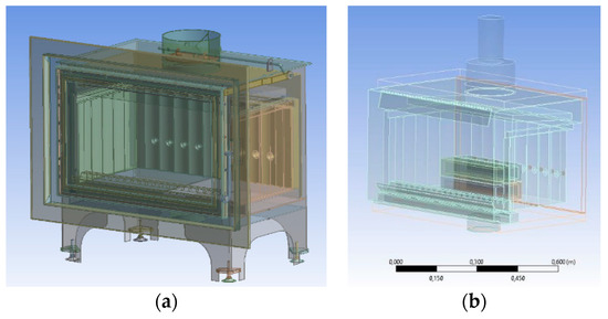
Figure 1.
(a) View of the fireplace insert; (b) wood model (Case 0) [13].

Table 1.
Basic properties of wood.
- The outer part: this is the source of gas corresponding to the part of the volatile component of the wood. Volumetric reactions are represented by Equations (1) and (2):C1.09 H2.1 O0.91 + 0.617∙O2 → 1.097∙CO + 1.054∙H2OCO + 0.5∙O2 → CO2.
- The inner part corresponds to the part of the solid component of the wood, on the surface of which the reactions described by Equations (3)–(6) take place:C(s) + 0.5∙O2 → COC(s) + CO2 → 2COC(s) + H2 O → H2 + COH2 + 0.5O2 → H2O.
The stoichiometric coefficients for modeling the homogenous reaction (Equation (1)) have been calculated using a mass balance to each of the volatile element species, i.e., C, O, and H. Data on the assumed burning time, as well as the amount of wood (with the composition given in Table 1), were determined according to the experiment prepared earlier. When defining the model, the following were assumed: the vacuum at the outlet to the chimney was equal to −10 Pa; the fuel weight during the 66 min of the burning cycle was 3.92 kg, and the value of the throttle opening was 50%. The fuel mass assumed in the model was divided into 3960 s, which corresponds to 66 min of combustion in real conditions. An experiment was carried out following the norm [12] that determines that measurements should be taken throughout the entire burning process. The measurement was made on a laboratory test bench equipped with the following:
- a flue gas analyzer recording the negative pressure, temperature, and flue gas composition (CO, CO2, and O2) in the chimney at a set distance from the outlet from the fireplace insert (Figure 2 and Figure 3a);
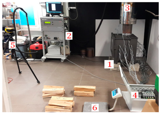 Figure 2. The facility of the testing bench: 1 fireplace insert with thermocouples, 2, 4 data acquisition units, 3 a vertical smoke conduit with mounted measuring section, 5 thermal camera, 6 electronic scale.
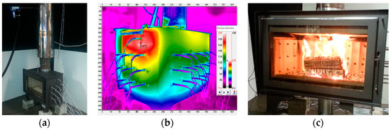 Figure 3. Testing bench facility, experiment: (a) fireplace with mounted thermocouples, (b) the view from the thermal imaging camera, (c) burning process [13].
 - a thermal camera registering the temperature on the surface of the walls and on the glass of the fireplace insert (Figure 3b); and,
- a set of thermocouples recording temperature at the walls in the furnace chamber (Figure 3a and Figure 4).
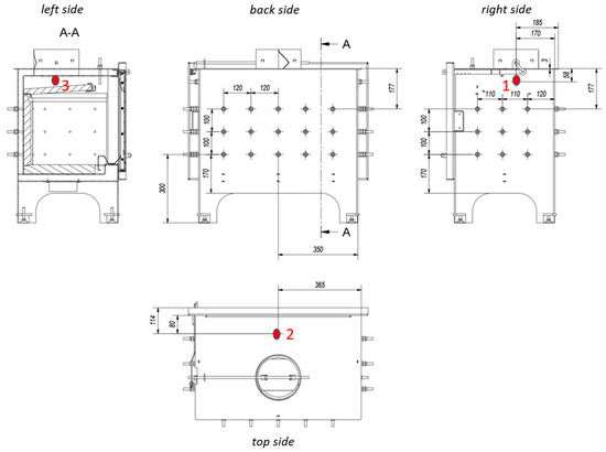 Figure 4. Diagram of three thermocouples’ placement in the fireplace insert chosen for the comparative study (Case 0).
The next stage of the work was the introduction of structural changes leading to the higher efficiency of the device. For this purpose, a second numerical model was prepared covering the structural changes. It was assumed that the structural changes should be directed at increasing the heat exchange surface with the environment. Based on the measurement results of exhaust emissions, temperature, and simulation results obtained at the stage of preparation of the numerical model (Case 0), we decided to analyze several design options. The first of these (Case 1) consisted of extending the flue (Figure 5a), whose task was to extend the exhaust gas path and create an additional surface ensuring heat exchange with the environment. The second one (Case 2) assumed the addition of through channels (Figure 5b), whose purpose was to increase the heat exchange surface and disconnect the channels supplying additional air on the rear wall of the fireplace insert to simplify the design. The third (Case 3) assumed leaving the extended flue with through channels and leaving the channels supplying additional air on the rear wall of the fireplace insert (Figure 5c).
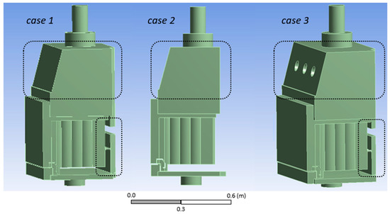
Figure 5.
Three designs for a modified fireplace insert construction (Cases 1, 2, and 3) with marked structural elements that have been modified.
The chimney loss remains crucial in the final balance of thermal efficiency of the fireplace insert [12], expressed according to Equation (7):
where qa is the relative flue gas loss and qb is the relative loss of incomplete combustion.
η = 100 − (qa + qb),
Relative flue gas loss is directly proportional to the flue gas temperature in the chimney [12], which is why, in the analysis of fireplace insert design modification, it was decided to minimize the flue gas temperature in the chimney while maintaining CO emissions at the same level with the same fuel expenditure. The calculations were carried out using the numerical modeling technique from the first stage of the work (Case 0). The fuel output, vacuum in the chimney flue, and other boundary conditions were the same as in the first model (Case 0).
3. Simulation and Results
The degree of the simplification of the numerical model required conducting a parallel experiment at the laboratory stand for the first numerical model of the fireplace (Case 0). Two sets of data were analyzed, i.e., the composition of exhaust in the chimney, as well as the temperature values indicated by the thermocouples (Figure 6, Figure 7 and Figure 8). Analyzing the results for the full work cycle of the fireplace insert, i.e., 66 min, it can be seen that, 15 min after the fireplace starts burning, there is a period between 15 and 45 min in which the operating conditions of the heating system are stabilized. The heating system reaches the highest flue gas temperature at the 45th min, after which the burning-off stage begins until the available fuel is consumed. Therefore, data from the numerical model (Case 0) were referred to for the period of stable operation (between 15 and 45 min). Table 2 presents the results of measurements and simulations in the chimney (Case 0). These are the results for the outlet plane to the chimney. In addition, the temperature values for three thermocouples, located as depicted in Figure 4, were compared (Figure 9). It is worth noting that the individual values are at a similar level and are subject to differences of several percentage points. Such differences may be acceptable considering the model simplifications that were made and the complex nature of the phenomena occurring in the said installation. The next stage of the work was to introduce construction changes leading to higher device efficiency. Based on the measurements taken and the results of simulations obtained at the stage of preparing the numerical model, a structural variant involving a change in the flue geometry was analyzed. Our task was to extend the route of the flue gas and create an additional surface to ensure the exchange of heat with the surroundings by swirling the exhaust stream.
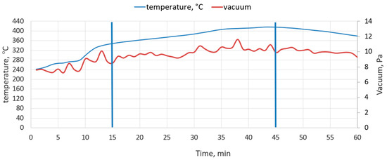
Figure 6.
Vacuum in the combustion chamber and exhaust gas temperature during the full combustion cycle (Case 0).
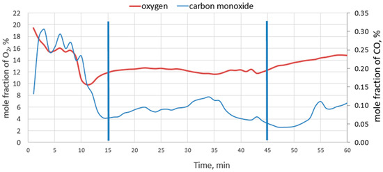
Figure 7.
The concentration of O2 and CO in the exhaust gas during the full combustion cycle (Case 0).
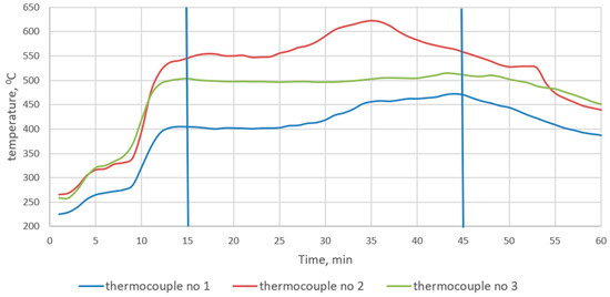
Figure 8.
Change in temperature as a function of time for the three thermocouples (1, 2, and 3) shown in Figure 4, which register the exhaust gas temperature flowing around the deflector (Case 0).
Table 2.
Measurement and simulation data acquired in the chimney.
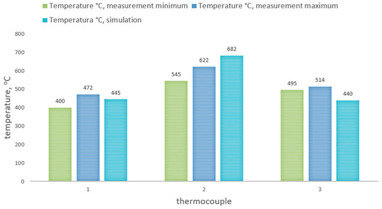
Figure 9.
Temperature values (°C) comparison of the three thermocouples obtained from measurement and simulation (Case 0).
Figure 10, Figure 11 and Figure 12 present the distribution of gas molecules along the temperature scale, as well as the predicted CO and O2 concentrations in selected areas of the fireplace insert. The gas molecules in Figure 10a (Case 0) confirm the vertical flame propagation that could be observed during a bench experiment (Figure 3c). In the modified constructions, the redesigned flue gas chamber facilitates elongation of the exhaust gas path in the temperature zone, ensuring the combustion of the remaining combustible gases in the exhaust gas and minimal CO emission to the chimney. The obtained swirling of exhaust causes intense heat exchange with the environment and thus a reduction in the temperature of the flues in the chimney, which is directly related to the improvement of the efficiency of the modified fireplace insert. In both cases (Case 1 and Case 3), it should be emphasized that the holes in the back wall of the focal chamber fulfill their role of eliminating zones with a high concentration of CO. This treatment is necessary because the furnace chamber is characterized by large changes in temperature and the resulting lower temperature zone and high CO concentration can affect the emission standards obtained in the chimney. A comparison of the temperature in the chimney flue for all three variants of the modified structure (Figure 13) indicates that the most advantageous solution is the last design (Case 3). Figure 14 shows the final proposal for the fireplace insert (Case 3), together with a visualization of the swirl of exhaust gases that intensifies heat exchange with the environment heating installation. The recommended structural changes contribute to improving the efficiency of the final heating device.
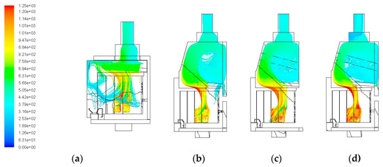
Figure 10.
Path of the gas molecules and change of the temperature (°C) in the fireplace insert combustion chamber for: (a) Case 0, (b) Case 1, (c) Case 2, (d) Case 3.
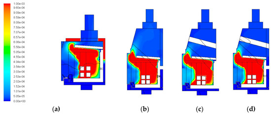
Figure 11.
Concentration of CO (mole fraction) for (a) Case 0, (b) Case 1, (c) Case 2, (d) Case 3.
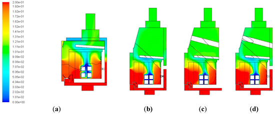
Figure 12.
Concentration of O2 (mole fraction) for (a) Case 0, (b) Case 1, (c) Case 2, (d) Case 3.
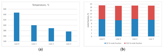
Figure 13.
Comparison for the analysis structural variants of the fireplace insert (in the outlet plane of the fireplace for (a) temperatures; (b) O2 and CO2 emissions.
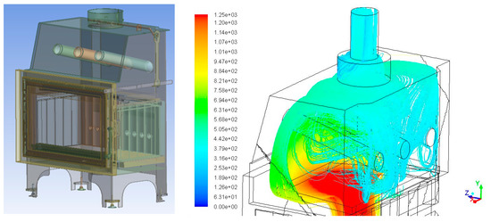
Figure 14.
Gas particle paths in the fireplace (Case 3)—temperature scale (°C).
4. Conclusions
The need to implement many models of heating installations up to 20 kW with similar parameters under systematically tightened environmental standards means that numerical modeling of combustion processes and heat exchange is becoming an interesting method of rapid prototyping. The proposed computational technique, despite the introduction of model simplifications, allows for obtaining numerical data to lead to new construction designs within a few hours with the assumption of a numerical grid of 3–4 million elements. The obtained results show that the average temperature in the chimney flue was reduced relative to Case 0 by 11%–16% in all cases. Comparing the modified construction (Case 3) and the initial variant (Case 0), the design changes in the final design were recommended. The redesign of the smoke conduit to increase the heat exchange surface and flue gas turbulence, as well as modification of the air supply ducts to the rear wall of the combustion chamber, contributed to the lowering of the flue gas temperature, and thus the reduction of the chimney losses of the installation. Transient CFD simulations of log-fired stoves can be part of further research.
Author Contributions
P.M. was responsible for the preparation of the numerical burning process, numerical models, the conduction of the simulation, and a summary of the research. M.W. was responsible for the measurement methodology, the preparation of the testing equipment demands, and the analysis of the data. J.B. was responsible for supervision of the testing laboratory and the coordination of the tests. B.P. was responsible for conducting the measurements, the preparation of measuring equipment, and the preparation of the CAD model for the Case 0 simulation. R.K. was responsible for the preparation of the testing bench according to the codes, and the preparation and conducting of the thermal measurements. All authors have read and agreed to the published version of the manuscript.
Funding
This research was funded by National Centre for Research and Development, Poland, grant number POIG.01.04.00-14-351/13.
Conflicts of Interest
The authors declare no conflict of interest.
References
- Lazaroiu, G.; Mihaescu, L.; Pisa, I.; Negreanu, G.P.; Berbece, V. The role of agricultural biomass in the production of ecological energy in Romania. In Proceedings of the International Multidisciplinary Scientific Geoconference, Albena, Bulgaria, 30 June–9 July 2018; Volume 18, pp. 721–726. [Google Scholar]
- Lazaroiu, G.; Mihaescu, L.; Negreanu, G.; Pana, C.; Pisa, I.; Cernat, A.; Ciupageanu, D.A. Experimental investigations of innovative biomass energy harnessing solutions. Energies 2018, 11, 3469. [Google Scholar] [CrossRef]
- Xing, T.; Lin, H.; Tan, Z.; Ju, L. Coordinated Energy Management for Micro Energy Systems Considering Carbon Emissions Using Multi-Objective Optimization. Energies 2019, 12, 4414. [Google Scholar] [CrossRef]
- Martín-Gamboa, M.; Dias, L.C.; Quinteiro, P.; Freire, F.; Arroja, L.; Dias, A.C. Multi-Criteria and Life Cycle Assessment of Wood-Based Bioenergy Alternatives for Residential Heating: A Sustainability Analysis. Energies 2019, 12, 4391. [Google Scholar] [CrossRef]
- Menghini, D.; Marra, F.S.; Allouis, C.; Beretta, F. Effect of excess air on the optimization of heating appliances for biomass combustion. Exp. Therm. Fluid Sci. 2008, 32, 1371–1380. [Google Scholar] [CrossRef]
- Sornek, K.; Filipowicz, M.; Rzepka, K. Study of clean combustion of wood in a stove-fireplace with accumulation. J. Energy Inst. 2017, 90, 613–623. [Google Scholar] [CrossRef]
- Carvalho, R.L.; Vicente, E.D.; Tarelho, L.A.C.; Jensen, O.M. Wood stove combustion air retrofits: A low cost way to increase energy savings in dwellings. Energy Build. 2018, 164, 140–152. [Google Scholar] [CrossRef]
- Scharler, R.; Benesch, C.; Neudeck, A.; Obernberger, I. CFD based design and optimisation of wood log fired stoves. In Proceedings of the 17th European Biomass Conference and Exhibition, From Research to Industry and Markets, Hamburg, Germany, 29 June–3 July 2009; p. 7. [Google Scholar]
- Menghini, D.; Marchione, T.; Martino, G.; Marra, F.S.; Allouis, C. Numerical and experimental investigations to lower environmental impact of an open fireplace. Exp. Therm. Fluid Sci. 2007, 31, 477–482. [Google Scholar] [CrossRef]
- Bugge, M.; Skreiberg, Ø.; Haugen, N.E.L.; Carlsson, P.; Seljeskog, M. Predicting NOx Emissions from Wood Stoves using Detailed Chemistry and Computational Fluid Dynamics. Energy Procedia 2015, 75, 1740–1745. [Google Scholar] [CrossRef]
- Ansys Fluent Theory Guide Release 16.2. Available online: http://www.pmt.usp.br/ACADEMIC/martoran/NotasModelosGrad/ANSYS%20Fluent%20Theory%20Guide%2015.pdf (accessed on 24 February 2020).
- The Standard EN 13229:2001/A1:2003/A2:2004/AC:2007 Inset Application Including Open Fires Fired by Solid fuels—Requirements and Test Methods. Available online: https://standards.cen.eu/dyn/www/f?p=204:110:0::::FSP_PROJECT,FSP_ORG_ID:20787,6276&cs=18A8C4C833F81E864263EB7558C3F6684 (accessed on 24 February 2020).
- Motyl, P.; Wikło, M.; Olejarczyk, K.; Kołodziejczyk, K.; Kalbarczyk Rafałand Piechnik, B.; Bukalska, J. Numerical Analysis of the Combustion Process in the Wood Stove. In Renewable Energy Sources: Engineering, Technology, Innovation; Wróbel, M., Jewiarz, M., Andrzej, S., Eds.; Springer International Publishing: Cham, Switzerland, 2020; pp. 229–237. [Google Scholar]
© 2020 by the authors. Licensee MDPI, Basel, Switzerland. This article is an open access article distributed under the terms and conditions of the Creative Commons Attribution (CC BY) license (http://creativecommons.org/licenses/by/4.0/).