Abstract
Recently, virtual synchronous generators (VSGS) are a hot topic in the area of microgrid control. However, the traditional fixed-parameter-based VSG control methods have an obvious disadvantage. Namely, if the damping value is set to be small, the amplitude of frequency deviations under external power disturbances is large, meaning that the frequency suppression capacity is insufficient, but if the damping value is large, the dynamics of the system will be greatly sacrificed. To solve the problem, taking the dynamic characteristics and the maximum allowable frequency deviation (MAFD) into account, in this paper an improved fuzzy adaptive damping-based VSG control strategy is proposed to simultaneously attenuate the microgrid frequency fluctuations and guarantee the system dynamics. Firstly, in order to address the necessity of using an adaptive damping-based VSG, the structure of a fixed-parameter VSG method that incorporates the f-p/Q-V droop controllers is introduced, based on which a small signal model is established to discuss the impacts of the virtual damping on the frequency response characteristics concerning the different penetration levels of power disturbances. Then, considering the dynamics and MAFD, a fuzzy adaptive controller is constructed relying on the well-designed membership functions, control rules and output scaling factors. The main feature of the improved fuzzy controller is that two alternative output scaling factors are employed to allow the system to be overdamped when the frequency deviation is large and undamped when the frequency deviation is small, balancing the frequency response dynamics and stability characteristics. To verify the effectiveness of the proposed fuzzy adaptive damping-based VSG technique, a computer simulation is conducted on a microgrid system in MATLAB/Simulink, and the obtained results are compared with the conventional droop control and fixed-parameter based VSGs. By using the proposed fuzzy adaptive damping-based VSG control method, the peak frequency deviations under the large power disturbances would become at least 8% lower compared to the traditional droop control and fixed-parameter VSG control, and meanwhile, the frequency response speed is fast when the disturbance stands at a low position. Consequently, it is valuable to promote the proposed techniques in engineering.
1. Introduction
Due to the advantages of low cost, flexibility and environmental friendliness, microgrid systems (e.g., diesel, wind and photovoltaic power generation systems, etc.) are gaining increasing attention in the area of energy generation and supply [1,2,3,4]. In practice, microgrids can play different roles, including grid-forming, grid-feeding and grid-supporting [5]. In detail, grid-forming is to establish a local grid that is powered only by the microgrid systems; Grid-feeding means that the microgrids will inject specified power into the CG through the PCC; Grid-supporting aims to use the microgrid or distributed generation systems to back up the CG by regulating its voltage/frequency and sharing active/reactive power. Generally, in order to achieve these functionalities or connect a microgrid to the CG, VSIs together with particular control algorithms must be employed to transfer the DC voltage into the AC one with the rated frequency [6].
The traditional VSI control strategies include P-Q droop control, V-f control and droop control, which target directly controlling the inverter to exert its function [7,8]. P-Q control is also known as constant power control. Without taking the frequency and voltage into account, only the active and reactive power injected into the grids are controlled to maintain at the reference levels. By contrast with P-Q control, V-f control aims to regulate the output voltage and frequency to stand at the rated values despite of the power changes. Droop control can be further divided into P-f/Q-V control and f-P/V-Q control, of which differences mainly reflect in the control topology [9,10]. In terms of P-f/Q-V control, the outer control loops are used for power regulation while the inner ones are for frequency and voltage regulation, just standing at the opposite position of the f-P/V-Q control. In addition to the basic droop control strategies, in [11], an enhanced droop control algorithm is adopted to mitigate the impacts of grid fluctuation on power flow control by using the feedforward structure. Literature [12] incorporates the voltage-shifting and load current feedforward control approaches into the droop control process, achieving better control performance. Crucially, these direct control schemes have fast dynamics. However, they are unable to provide the microgrids with sufficient inertia and damping like the RSG, which can prevent acute voltage and frequency fluctuations when the external disturbances (load changes) emerge, posing potential risks to the safety and reliability of the whole gird [13,14].
In order to solve the stability problem of the microgrids and ensure the synchronization of the grid-connected VSI when external disturbances occur, in 2007, Beck proposed the concept of VSG that simulates the behaviors of the RSG [15]. Specifically, by integrating the swing function of the RSG into the VSI control process, the microgrids can possess the characteristics of virtual inertia and damping. It deserves to be mentioned that the VSG in [15] is a current-type controller, which means that the currents are the feedback states for power regulation, playing a small role in voltage and frequency support. On this ground the voltage-type VSG is developed [16,17]. Relying on the relationship between the rotor inertia and the frequency characteristics of the VSG and the relation of the reactive power and voltage, the frequency and voltage are fed back and treated as the targeting control variables in the voltage-type controllers. In this case, the output voltage, frequency and power of the VSI can be regulated simultaneously. To simulate the RSG more accurately, in addition to the mechanical properties, Zhong incorporated the electromagnetic characteristics and established a more comprehensive VSG model [18]. Undoubtedly, these studies have laid the ground for enhancing the power quality and stability of the grid and the microgrids by the use of VSG technologies. However, the addition of the traditional VSG with the constant virtual inertia and damping values cannot completely avoid the risks of frequency and active power oscillation in view of the penetration levels of the external load disturbances [19], especially when the inertia and damping values stand at the low positions, but if the inertia and damping are large, the transient control performance would be sacrificed [20]. To tackle these problems, several up-to-date self-adaptive control methods have been developed in [21,22,23,24,25,26]. In [21], a VSG with alternating inertia, which is based on bang-bang control theory, is established to enhance the fast response of the virtual machine in tracking the steady-state frequency. Reference [22] obtained the real-time virtual inertia by solving a second-order optimization problem, and in [23], particle swarm optimization is implemented to find the inertia of the VSG unit, which results in the desired performance. However, the optimization procedures are hard to implement. Both the inertia and damping are altered according to the linear control laws in [24,25] to support the frequency stability. Although this kind of method contributes to suppressing the severe frequency oscillations, it is important to highlight that the VSG and grid characteristics are nonlinear in practice, so the linear control laws are not the optimal solutions. The nonlinear adaptive rotor inertia control methods are introduced in [26,27], but the inertia matching strategies are deduced based on accurate power calculations. Hence, the robustness of the methods is low. On this ground [28,29,30,31] adopt the fuzzy controllers to tune the inertia of the VSG, which comply with the nonlinear properties of the system and are relatively simple and robust, but there still exist several problems. Firstly, the damping that is also closely related to the frequency response (as in [24]) is seldom separately employed for frequency fluctuation attenuation in these researches, which means that the fuzzy adaptive damping VSG control technology needs further investigation. Secondly, the reasons why the metabolic parameters can attenuate the frequency fluctuations are not explained by using the control principles. Thirdly, regardless of the penetration levels of the external disturbances, the frequency fluctuations should be limited to a specified range (e.g., ±0.5 Hz) for the grids. However, this aspect has never been considered previously when designing a fuzzy controller.
This paper presents a fuzzy adaptive damping control strategy to adjust the real-time parameter of the VSG so as to simultaneously guarantee the frequency stability and the dynamics of the grid-connected microgrids. Firstly, in order to illustrate the impacts of the damping values on the frequency characteristics under power disturbances, a small-signal model of the VSG control system is established after introducing its structure, and on this ground the system performance is analyzed according to the automatic control theories. Secondly, taking the MAFDs into account, an improved fuzzy controller is established to generate the real-time damping values for the high-performance VSG. The main novelties and contributions of this research in comparison with the existing researches include that firstly, the virtual damping rather than the inertia is mainly used for frequency fluctuation attenuation and it is adjusted by a fuzzy logic controller. Then, the reasons why and how a parameter-adaptive VSG contributes to the microgrid frequency stability improvement are theoretically illustrated, laying the ground for the future relevant researches. Thirdly, by adopting the alternative output scaling factors, the proposed fuzzy damping controller is able to actuate the whole VSG control system to be overdamped or undamped according to the magnitude of frequency deviations, compromising the frequency stability and system dynamics as much as possible.
The structure of the rest paper is as follows: Section 2 introduces a fixed-parameter VSG control strategy and the impacts of the virtual damping on the system performance. In Section 3, the design process of the proposed fuzzy adaptive damping control based VSG is presented. Section 4 compares the simulation results of different control strategies, and Section 5 is the conclusion part.
2. Fixed-Parameter VSG Control and Parametric Analysis
This part introduces a fixed-parameter VSG control strategy which incorporates f-P and Q-V droop mechanisms for frequency and voltage regulation at first. On this ground the impacts of the damping on the frequency characteristics are analyzed theoretically, addressing the necessity and providing the guidelines for employing an adaptive parameter VSG control method.
2.1. Fixed-Parameter VSG Control Incorporating f-P and Q-V Droop Mechanisms
As for a microgrid system, the VSG control topology is illustrated in Figure 1. Generally, the energy storage component, bus capacitor, inverter and VSG control algorithms constitute the VSG. This paper mainly focuses on the VSG control which comprises the power calculation part, voltage and frequency extraction part, f-P droop 3 control part, virtual rotating function part and excitation regulation part with inner Q-V droop structure.
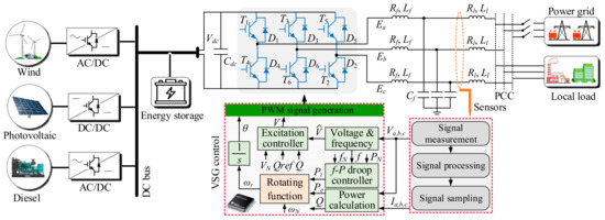
Figure 1.
VSG control strategy for microgrid.
(a) Voltage and frequency extraction part
The detected voltage and current signals from the PCC cannot be directly used for voltage and frequency regulation unless the amplitude and frequency of voltage have been extracted. In this paper, a three-phase PLL whose structure is shown in Figure 2 is employed to obtain the real-time voltage amplitude and frequency [32].
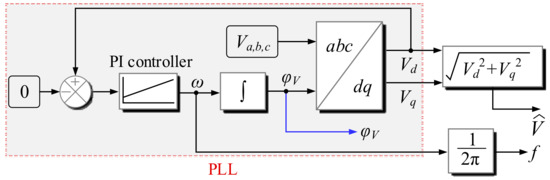
Figure 2.
Block diagram of PLL for voltage.
It can be noted that firstly, the measured phase voltages are transformed to the ones in the rotating reference frame, that is, the d, q-axis voltages Vd and Vq, respectively [33,34]:
Then, a PI controller is adopted to regulate the errors between Vd and the reference value (zero), and the output of the PI controller is the angular frequency ω of the voltage and it is also treated as the working speed of the VSG. After imposing integral operation on ω, the result can be locked to the instantaneous phase-angle of the voltage. Finally, the real-time voltage frequency f and amplitude V can be obtained:
(b) Power calculation part
It is widely acknowledged that the active power and reactive power are related to the VSG frequency and voltage performance (both steady-state and dynamic characteristics), respectively. For a VSG control strategy, the active and reactive power regulation loops require to be integrated into the control process, making it necessary to calculate the active and reactive power of the grid. Relying on the measured Va,b,c and Ia,b,c, the active power Pe can be presented as:
The phase angle of current can be obtained by using a three-phase PLL like Figure 2, where the voltage signals are replaced with the currents. Further, the reactive power Q is:
(c) f-P droop control part
f-P droop control is part of the frequency regulation loop, serving for primary frequency control and calculating the output mechanical power Pt for the VSG. It is achieved by simulating the droop characteristics of an RSG. The theoretical foundations for establishing an f-P droop controller are as follows: Regarding the active power of PCC (Pe) as the electromagnetic power of the generator, at the moment when the load of the generator deviates from the rated value, the electromagnetic power would change immediately. However, the mechanical power of the generator responds much slower, resulting in imbalance between Pt and Pe. Further, due to the power imbalance, the generator speed will witness a synchronous fluctuation. In this case, to ensure that the output power can adapt to the load variations, the mechanical power needs to be regulated by the controller so as to return to an equilibrium state. However, as for a generator, even if the power balance is restored, the speed cannot reach the previous position, which means that the microgrid frequency would deviate from the initial level once the output power shifts. Figure 3a depicts the relation of the output mechanical power of a generator versus its angular speed, where ω = 2πf. It can be seen that as the output power increases, the generator speed will decline, and this is the so-called droop characteristics of a generator.
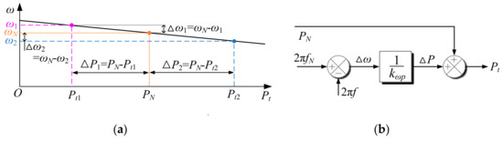
Figure 3.
Explanations of f-P controller. (a) Relation between the output mechanical power and angular speed for a generator; (b) Structure of an f-P controller.
We define the droop coefficient kw as:
Obviously, kw is negative. For the sake of simplicity, denote kw p = −kw, which is a positive value. Then, select the microgrid frequency as the variable to be manipulated (reference), and the errors between the feedback frequency and the rated frequency can be used to calculate the required output mechanical power for the VSG:
The structure of the f-P controller is shown in Figure 3b. It is important to address that the primary frequency regulation mainly aims to allocate sufficient power to the grid, and consequently, the secondary frequency control based on VSG needs to be adopted to further stabilize the system frequency, which is one of the main purposes of this paper.
(d) Virtual rotating function part
The virtual rotating function that is derived from an RSG is the core of VSG control technique, endowing the microgrid with inertia and damping. It also has the functions of the secondary frequency control and control angle θ calculation. By ignoring the complex coupling properties of the generator, the characteristics of the VSG can be reflected by a second-order model as follows:
Usually, the virtual inertia and damping are set as the certain levels, which is well-known for the so-called fixed-parameter VSG control. According to the mathematical model of VSG, the block diagram of the virtual rotating function part is illustrated in Figure 4.
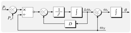
Figure 4.
Block diagram of the virtual rotating function part.
(e) Excitation regulation part
The excitation regulation part, through which the voltage amplitude used for generating the PWM signals can be obtained, is employed to control the output voltage of the VSG. In this paper, the excitation regulation process is mainly achieved by simulating the droop characteristics in regard to the output voltage versus the reactive power and the closed-loop control theory. Firstly, because the relation between the terminal voltage and the reactive power for a generator is identical to that between the speed and the reactive power (as in Figure 3a, the Q-V droop controller that can be used to compute the required voltage Vref after the reactive power changes from the reference value Qref to Q can be represented as follows:
Traditionally, Vref will be directly used for PWM signal generation. However, in order to further ensure that the output voltage of the inverter equals the desired value, as is shown in Figure 5, a PI controller that can realize zero-error output adjustment is utilized for closed-loop control in this paper. So far, both V and θ are ready for PWM signal generation following the procedures in [35].
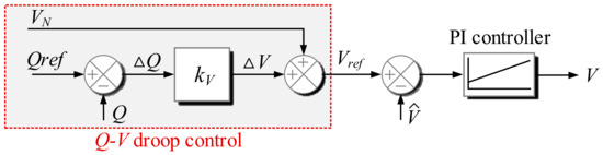
Figure 5.
Structure of excitation regulation part with inner Q-V droop control.
2.2. Impacts of Damping on Frequency Characteristics
Intuitively, after adopting the VSG control technology, the microgrid will show similar characteristics as a generator. When the load deviates from the desired value, the power or torque imbalance is inclined to cause frequency fluctuations. However, as for (7), assuming that the result of its left term is fixed (frequency change rate is specific), it can be rewritten as:
It can be noted that the larger D is, the smaller the speed deviation will become with respect to the same power imbalance, representing that the damping is able to attenuate the frequency fluctuation.
Undoubtedly, the abovementioned discoveries based on numerical analysis are intuitive, and they need to be supported by the theoretical control theories. In order to achieve this goal, for the sake of simplicity, by ignoring the delay effect of the PLL, a small-signal model for the VSG’s frequency regulation loop is established as in Figure 6. The f-P control part is equivalent to a proportional element; The inverter is approximated as a gain K which can be set as 1 for the high-performance PWM method; ΔP is the load variations, and it can be regarded as an external disturbance. Then, the standard closed-loop transfer function Gf(s) between the frequency input and output is described as:
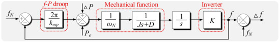
Figure 6.
Small-signal model for VSG’s frequency regulation loop.
We note that the system is a typical second-order system, and because , the system is able to remain stable finally regardless of the input types and the magnitude of D and J. Moreover, in order to discuss the frequency fluctuation issue under the external active power disturbances, the transfer function Gd(s) between the power disturbance and the frequency fluctuation is established as follows:
It is interesting to note that , and (10) and (11) differ only by a gain factor. Next, the frequency dynamics under power disturbances are going to the discussed on the basis of (11).
In (11), K, ωN and kwp are relevant to the system properties and they are fixed in practice, leading to the fact that D and J, which can be manipulated, are the only parameters that can influence the system dynamics. Moreover, because we mainly discuss the impacts of D on the system performance, J is assumed to be constant in this study as well. Theoretically, the second-order system can be further designed as an overdamped system or an undamped system by changing the values of D in (11). For the sake of explicit explanations, define ωna as the virtual natural frequency and ξ as the virtual damping ratio of the system as follows:
Commonly, when ξ > 1, that is, Equation (14) is satisfied, the system is overdamped. Otherwise, the system is undamped.
By using the introduced natural frequency and damping ratio, (11) can be rewritten as:
As for a sudden load (ΔP), apply the Laplace transformation to it and it can be obtained that:
Then, the output frequency fluctuation is:
By the use of inverse Laplace transformation, the system step response in the time domain is:
According to (16), the response of ΔP with the virtual natural frequency decreasing from ξ5 to ξ1 is depicted in Figure 7. When the system is undamped, the time for the frequency deviation to reach its peak (tp) and the corresponding output (Δfp) can be obtained as (19) and (20), respectively:
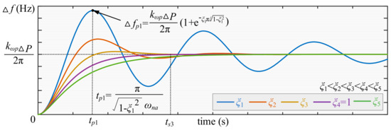
Figure 7.
Frequency fluctuation under different values of ξ.
It can be seen that as ξ increases from 0 to 2, the overshoot becomes smaller and it turns to be 0 when ξ > 1 (overdamped). In terms of the peak time, it is related to not only ξ but also ωna. Although the smaller ξ is or the larger ωna is, the shorter tp is, the settling time ts within which the frequency returns to the stable state is much more complicated. Reference [36] has shown the theoretical settling time for both the overdamped and undamped systems, which is related to both ξ and ωna. It deserves to be mentioned that in engineering, is called the optimal damping ratio. That is, when ξ = , ts becomes the shortest while the overshoot is acceptably small.
Traditionally, the main objective of microgrid frequency stability improvement (fluctuation attenuation) under power disturbances appertains to the peak deviation reduction. According to the above analysis, they can be achieved by changing the values of ξ, namely, D according to (13). In detail, when D increases, ξ rises while Δfp experiences a downward trend following (20). Therefore, despite of the external load disturbance intensity, D could be adjusted to a proper level to ensure that the frequency fluctuation can reach a relatively low position. This is exactly the reason why metabolic damping values contribute to the microgrid frequency stability, complying with the intuitive analysis above.
As far as the traditional fixed-parameter based VSG is concerned, the frequency fluctuation suppression capacity remains constant. If only a small load disturbance is witnessed, the frequency deviation is usually acceptable and not dangerous. Whereas, once a large disturbance occurs, the peak magnitude of the frequency fluctuation will go up, and it is possible that the frequency deviation exceeds the maximum allowable range, resulting in serious hazards to the grid. Hence, it is necessary to employ the adaptive damping to improve the frequency stability referring to different active power oscillations with uncertain external load disturbances. However, if only the magnitude of the peak frequency deviation is focused on when optimizing the VSG control algorithms, large damping (even overdamped system) will be adopted, sacrificing the settling time undoubtedly. This issue places great demand on developing an improved VSG that can guarantee both the microgrid frequency stability and the dynamic performance.
3. Proposed Fuzzy Adaptive Damping Based VSG Control
FLC, which was proposed in 1965, has been widely used in engineering [37]. FLC is a heuristic approach that easily embeds the knowledge and key elements of human thinking in the design of nonlinear controllers [38]. Qualitative and heuristic considerations, which cannot be handled by conventional control theory, can be used for control purposes in a systematic form [39]. FLC does not need an accurate mathematical model and can work with imprecise inputs and handle nonlinearity. Considering the advantages of the fuzzy logic controllers, it deserves further investigation in solving the remaining problems in the previous FLC-based VSG researches for the sake of higher performance concerning the grid frequency.
In this study, the fuzzy controller is utilized to adapt the virtual damping value for VSG control, enabling small-scale and fast active power and frequency response. The block diagram of the proposed VSG (rotating function part) based on self-adaptive fuzzy controller is shown in Figure 8. It can be seen that the features of the fuzzy adaptive controller include: (1) it is a two-dimensional fuzzy controller, of which inputs are the frequency deviation (Δf = f − fN) and the power disturbance (ΔP); (2) the fuzzy system consists of three inner parts, namely, fuzzification, fuzzy inference engine driven by the fuzzy control rules and membership function and defuzzification; (3) the final output of the controller is the calculated adaptive damping (Df) that equals the sum of the initial setting (D0) and the correction (ΔD) generated by the fuzzy regulation; (4) two alternative output scaling factors are designed creatively, and which one is to be used is relevant to the MAFD. The detailed design schemes and procedures of the proposed fuzzy controller are explained in this part.
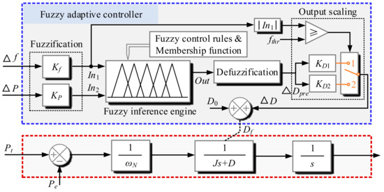
Figure 8.
Block diagram of the proposed fuzzy adaptive damping control based VSG.
3.1. Explanations of Two-Dimensional Fuzzy Controller Concerning Inputs and Output
On the one hand, referring to the previous analysis, when the power disturbance intensity is low, if the microgrid operates with a large value of virtual damping constant, longer settling time is needed for stabilizing the system frequency. In such a situation, the system only requires a small damping to attenuate the frequency fluctuations. On the contrary, if the power disturbances are large, a high damping value is required to reduce the oscillations of frequency, avoiding system instability or collapses. Hence, ΔP must be one of the most important inputs for the fuzzy adaptive damping regulator. On the other hand, in addition to ΔP which can be used to estimate the magnitude of the required damping, the frequency deviations are more intuitive to determine whether the in-service damping value is appropriate. When Δf approaches the maximum allowable range, the value of damping should be further enlarged. While if the frequency deviation is small, even though the power disturbance is large at the moment, D can be set to a relatively small level so as to ensure the fast dynamics. On this ground Δf is also a crucial input for the fuzzy controller. There still exists another advantage when considering the frequency deviation as the manipulated variable, that is, the subsidiary (output scaling design) conditions can be easily integrated into the controller, which will be detailed in Section 3.2.
When it comes to the output, differing from the traditional fuzzy adaptive controller that produces the final value directly used for control through the defuzzification part, a correction term that is added to D0 is generated instead. In engineering, D0 should meet the optimal damping ratio requirement (as in Section 2.2), where (21) is satisfied:
As the power disturbance or the frequency deviation gets larger, the value of ΔD gets larger as well, taking frequency fluctuation suppression as the first priority. By contrast, if the load power and frequency fluctuations do not need large damping for regulation, it can be set to zero or positive small values to improve the dynamics. The advantage of the proposed correction-term-based fuzzy controller reflects in that the output damping used for control will never become extremely small by mistake, avoiding the unwanted and risky frequency shifts so as to enhance the microgrid reliability.
3.2. Design of Fuzzy Controller Concerning Inner Components
(a) Fuzzification
Fuzzification is used to convert the actual input values to the fuzzy values. Here, the range of fuzzy domain is designed as [−1, 1]. Thus, In1 and In2 of the fuzzy controller can be formed as:
The input scaling factors are equal to:
(b) Fuzzy control rules
The fuzzy values of In1 and In2 are utilized for fuzzy inference on the basis of the rule base. Before formulating the specific control rules, define seven linguistic variables to describe the fuzzy variables, namely, PL, PM, PS, ZO, NS, NM and NL. For the inputs, the frequency and power fluctuations can be either positive or negative, so the fuzzy subset corresponding to them is {PL, PM, PS, ZO, NS, NM, NL}. Whereas, because the output of the controller is expected to be larger than or at least equal zero, the description subset for it is {PL, PM, PS, ZO}. The fuzzy control rules are the fundamental operation of the fuzzy logic for mapping the input signals to the output ones. Table 1 illustrates 49 rules extracted from the existing knowledge and practical experiences, which can be generally summarized as follows:

Table 1.
Fuzzy control rules.
- (1)
- When Δf is very large (either positive or negative), a large or medium positive value of ΔD should be applied to stabilize the system frequency depending on the magnitude of ΔP.
- (2)
- When both Δf and ΔP are relatively or very small, a zero or relatively small ΔD is employed. In these cases, the real and predicted frequency fluctuations are not severe at all, and the system dynamics are the control objectives.
- (3)
- When Δf is medium and ΔP is very large/small, a large/small value of ΔD should be used to ensure that the estimated frequency deviation is limited.
- (4)
- When Δf is medium and as long as ΔP is not very large or small, a medium ΔD is going to be adopted, ensuring that the system has acceptable dynamic performance as well as low fluctuations.
- (5)
- When Δf is small while ΔP is large or medium, ΔD is set to be medium in case of unlimited frequency fluctuations.
By using Table 1, the fuzzy control rules can be defined in the form of “if-then” as follows: if In1 is A and In2 is B, then out is C. A, B and C represent the fuzzy description subsets corresponding to each variable, out is the output of the fuzzy inference engine. According to the control rules, both the frequency deviations and response dynamics are taken into account comprehensively.
(c) Membership functions
The membership functions for the inputs map the normalized frequency deviation and power disturbance to the membership degree between 0 and 1, while the membership functions for the output plays an opposite role. In fuzzy logic, membership function represents the degree of truth as an extension of valuation, working together with the control rules so as to figure out the fuzzy inference problem quantitatively. The membership functions for Δf, ΔP and ΔD are illustrated in Figure 9, respectively. It can be seen that the output of the function ranges from 0 and 1, while the inputs are between −1 and 1, being in accord with the desired properties of the fuzzy controller. Interestingly, the intersections of NL and NM, PM and PL domains in Figure 9a, and PM and PL domains in Figure 9c are weak. This draws clear lines between the large and medium ranges for the frequency deviations and the output damping compensations. In this paper, by adopting these kinds of membership functions, when |In1| > 0.9, the frequency deviation will be directly identified as the large level. Meanwhile, when the output is inferred to be positive large by the fuzzy inference engine, the value of out should be over 0.9 after defuzzification.
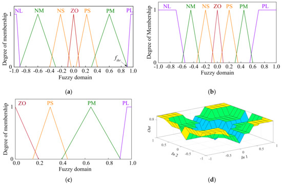
Figure 9.
Fuzzy membership functions. (a) Frequency deviation; (b) Power disturbance; (c) Output damping correction; (d) Relationship between inputs and output in the form of surface view.
(d) Defuzzification
The output of the fuzzy inference engine is neither a single value nor a numerical equation, but it is a fuzzy set. Defuzzification part aims to convert the fuzzy descriptions to a crisp value for control. In engineering, the most commonly-used strategy is the centroid defuzzification which contains most of the inference results [40]:
It needs to be mentioned that ΔDpre ranges from 0 to 1. Thus, scaling factors are required to adjust it to the appropriate level.
3.3. Design of Output Scaling Factors Considering MAFD and Dynamics
The most important goal of frequency regulation is to prevent the frequency deviation from reaching Δfmax, at which point the grid is definitely in danger. To achieve this goal, an effective solution is to employ large damping values to make the system overdamped. In this case, the overshoot is zero. However, if the damping always remains large, the frequency response speed gets down significantly. Consequently, if the external load is small, which cannot cause large frequency deviation even the system is designed to be undamped, large damping is not necessary at all. On these grounds a new issue of how to design the proper damping for the purpose of compromise arises. To solve this problem, this paper proposes a novel fuzzy control scheme as follows: as long as the frequency deviation is less than the defined threshold level fthr, which means there is still enough margin, the system is designed to be undamped (using small scaling factor KD1); but once the frequency deviation reaches a relatively high position, which means there is not enough margin, the damping value will jump to the high level to make the system overdamped (using large scaling factor KD2). It is also important to mention that this strategy requires to be achieved with the cooperation of the control rules and membership functions in Table 1 and Figure 9.
The design process for KD1 and KD2 are as follows. Firstly, the critical damping for the system can be calculated by:
When the real-time damping during control is higher than Dthr, the system is overdamped. Otherwise, the system is undamped. Therefore, for a undamped system, the value of ΔD should satisfy the following condition:
Hence:
For an overdamped system, the extreme damping can be several times larger than the critical damping, and the larger it is, the higher the maximum frequency deviation suppression capability the system gains. In this research, it is set as 0.5Dthr, that is:
The detailed selection and implementation process of the scaling factors are as follows. On the one hand, when the frequency deviation magnitude (In1) is smaller than fthr (fthr = 0.9 in this study), which might be in the subsets of NM, NS, ZO, PS and PM in Figure 9a, out can be ZO, PS, PM and PL. Hence, the range of ΔDpre is [0, 1], which is also determined by the power disturbance (In2). In this case, there is relatively enough frequency margin, so KD1 is selected for control, maintaining relatively fast response speed. On the other hand, when |In1| > fthr, the frequency deviation is considered to be dangerous, KD2 is selected for control. In this case, In1 belongs to either NL or PL, so out must be PL according to the control rules. In Figure 9c, because there are clear lines between the PL and the other subsets, after defuzzification, ΔDpre will mostly be in the range of [0.9, 1]. Consequently, the minimum and the maximum values of ΔD mostly range from 0.45Dthr (Df = 1.15 Dthr) to 0.5Dthr (Df = 1.21Dthr), ensuring the system is overdamped as far as possible whenever the frequency deviation is large.
By utilizing the proposed fuzzy system, the virtual damping constant can be automatically adjusted to track the changes in different penetration levels of load disturbances and frequency deviations, enabling self-adaptive response characteristics.
4. Simulation Results
In this part, simulation is carried out to verify the effectiveness of the proposed VSG control strategy. The main parameters of the test microgrid are shown in Table 2, and the structure of the proposed strategy in MATLAB/Simulink 2018b is shown in Figure 10. The important simulation setups include: (1) the control period is 5e−6 s; (2) the power disturbances can be imposed on the system by adding or reducing the load units; (3) the distributed generation systems are equivalent to a DC voltage source [41].
Table 2.
Main parameters of the microgrid.
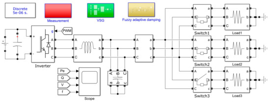
Figure 10.
Structure of the proposed fuzzy adaptive damping based VSG in Simulink.
For the sake of comparative discussion, apart from the proposed fuzzy adaptive damping based VSG, the simulation results of the traditional droop control (f-P/Q-V) and fixed-parameter based VSG control methods (the inertia and damping are set as the values of J and D0 in Table 2) are illustrated as well. In order to comprehensively compare the frequency fluctuation suppression characteristics and the system dynamics of these control algorithms, several different cases concerning different penetration levels of external power disturbances (the large and small load changes are suddenly imposed or removed) are studied, respectively.
(a) Increasing load power
At first, as for the traditional droop control method, the simulation setup is as follows. Before the algorithm is implemented, the output voltage, power and frequency are zero. Between 0 and 0.5 s, the load power remains at the rated level. Then, at 0.5 s, a sudden load change of 2 kVA (relatively small load disturbance) occurs, and at 1.0 s, the load changes from 12 kVA to 15 kVA (relatively large load disturbance). Figure 11 shows the system performance when the traditional droop control method is employed. Firstly, it can be seen that the power can stabilize at the desired positions after the transient process, and meanwhile the frequency will level off at the lower positions than the rated value due to the droop characteristics. The frequency fluctuations in the stable state are nearly zero, meaning that the steady-state performance is good. Secondly, at about 0.5 s, the peak power fluctuation reaches 15 kVA and the peak frequency deviation is 0.24 Hz (peak frequency fp is 49.76 Hz), and at about 1.0 s, they are 19 kVA and 0.5 Hz (peak frequency fp is 49.76 Hz), respectively. Thirdly, it deserves to be mentioned that the reactive power keeps zero because the resistive load serves as the load of the microgrid in simulation. In terms of the voltage, whenever the load power experiences a sudden change, it fluctuates inevitably, and the maximum fluctuation is about 40 V. Then, it is interesting that the frequency response to the external disturbance slightly lags behind the power and voltage response, which is called delay in this research. Finally, because the system is endowed with low inertia and damping, the frequency response speed is very high and the peak time is about 0.056 s, while the settling time is long (0.25 s) when the power disturbance is 2 kVA. Similarly, when the power disturbance is 3 kVA (power deviation changes from 2 kVA to 5 kVA), the peak time is short (0.052 s) but the settling time is long (0.17 s) as well. Comparatively speaking, the power and voltage response speed is much faster. When the power disturbances are suddenly imposed on the system, the settling time is about 0.02 s. Active power overshoot can be witnessed when the load power changes, and they are 25% and 26% at 0.5 s and 1.0 s, respectively.
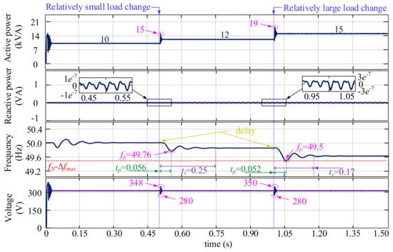
Figure 11.
Simulation results of the traditional droop control strategy under different penetration levels of load disturbances.
Further, Figure 12a,b illustrates the control performance of the fixed-parameter VSG and the proposed fuzzy adaptive damping-based VSG algorithms, respectively. Differing from Figure 11, in which the maximum frequency deviation reaches Δfmax when the power deviation is 5 kVA, the maximum power disturbance is set as 5 kVA (at 1.5 s, the load power changes from 15 kVA to 20 kVA) in Figure 12a,b.
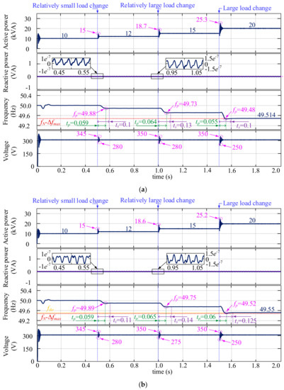
Figure 12.
Simulation results of different VSG control strategies under different load disturbances. (a) Fixed-parameter based VSG; (b) Proposed fuzzy adaptive damping based VSG.
Compared to the traditional droop control strategy, although the power and voltage fluctuations experience a similar shift trend for the two VSG control methods, the frequency response characteristics are totally different. In detail, the active power overshoots are 25% and 26% at 0.5 s and 1.0 s, respectively, and the voltage and power response time are similar to those in Figure 11. Besides, the steady-state performance is markable regardless of power, frequency and voltage. Interestingly, the frequency response still lags behind the power and voltage response, representing that the frequency and power performances are totally different in terms of the microgrid control even we assume that the microgrid has similar droop characteristics as an RSG. However, as for the frequency characteristics, firstly, at 0.5 s and 1.0 s when 2 kVA (relatively small) and 3 kVA (relatively large) disturbances are imposed, respectively, only small overshoots are witnessed for both VSG control techniques. In detail, the peak frequency deviations are 0.12 Hz and 0.11 Hz at 0.5 s, and 0.27 Hz and 0.25 Hz at 1.0 s in Figure 12a,b, respectively. The reason why the peak frequency deviation of the fixed-parameter based VSG is slightly larger than that of the proposed VSG is that the real-time damping for the latter scheme must be larger than 4.0. Secondly, the peak time for the VSG control methods are obviously larger than that for the droop control method. tp is 0.059 s and 0.064 s when 2 kVA and 3 kVA power disturbances are imposed in Figure 12a, respectively, and it is 0.059 s and 0.065 s for the fuzzy adaptive damping-based method, respectively. However, the settling time for the VSG control methods are smaller than that for the droop control method. For the fixed-parameter VSG, ts is 0.1 s and 0.13 s at around 0.5 s and 1.0 s when the power disturbances occur, respectively. In terms of the improved VSG, ts is a bit longer than that in Figure 12a due to the larger real-time damping values, it is 0.11 s and 0.14 s when the relatively small and relatively large disturbances are imposed on the system, respectively. Importantly, it can be seen that the VSG control strategies show better frequency stability when the power disturbance penetration level is high. In detail, at 1.0 s when a relatively large load change occurs, unlike the traditional droop control method, the maximum frequency deviation is still far away from the dangerous level. This represents that the VSG control method is able to provide spectacular frequency support by the means of virtual inertia and damping to the microgrid.
Before leaving Figure 12, it can be noted that at around 1.5 s when the large load disturbance is imposed on the system, the frequency overshoot appears not only in Figure 12a but also in Figure 12b. Whereas, it needs to be mentioned that the working mechanisms of them are totally different. As for the fixed-parameter VSG, because the damping is 4.0 constantly and the system is undamped, the overshoot appears due to the inner property. But as far as the improved VSG is concerned, as long as the frequency deviation is over 0.45 Hz (fthr), the real-time damping will be automatically adjusted to the level that makes the system overdamped by the improved fuzzy adaptive damping controller. In this case, the frequency will shift much slower and it just continues to rise because of the inertance, leading to the final result that Δfp is 0.48 Hz (fp stands at 49.52 Hz) in Figure 12b, which is 8% smaller than the frequency deviation (0.52 Hz) in Figure 12b. Obviously, the improved fuzzy adaptive damping based VSG successfully suppress the frequency deviation within the maximum allowable range when the power disturbance is large, contributing to the system frequency stability. Finally, it is interesting to see that when the load power remains 20 kVA, the stable operating frequency of the fixed-parameter VSG is nearly 49.514 Hz (Δfp = 0.486 Hz), while it is 49.55 Hz (Δfp = 0.45 Hz) for the proposed adaptive damping based VSG. Comparatively speaking, the improved method can provide stronger frequency support to the microgrid.
(b) Reducing load power
Unlike the situations where the load power changes are suddenly imposed on the microgrid, it is unreasonable to remove 100% of the load power to make the microgrid operate under no load. On this ground the simulation setups are modified as follows: The system starts from a standstill state. That is, the output voltage, power and frequency are zero as well. Between 0 and 0.5 s, the load power remains at the rated level. At 0.5 s, a sudden load change of 2 kVA (a relatively small load disturbance) occurs. At 1.0 s, a load change of 5 KVA (from 8 kVA to 3 kVA) regarded as the large load disturbance is implemented. Figure 13 illustrates the simulation results of the traditional droop control, fixed-parameter VSG control and proposed VSG control algorithms, respectively.
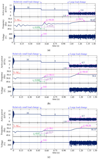
Figure 13.
Comparative simulation results of the different control strategies under different load disturbances. (a) Traditional droop control (b) Fixed-parameter based VSG; (c) Proposed fuzzy adaptive damping based VSG.
On the one hand, it can be seen that the system is stable when the load change is small regardless of the control methods. In detail, first, the active power in Figure 13a–c can stabilize at the desired position without errors after transient regulations, and like the results in Figure 11 and Figure 12, although the frequency responses lag behind the power responses in Figure 13, they can get stable at last (between 0.9 s and 1.0 s). Second, when a load of 2 KVA is removed, the active power quickly gets down to 8 kVA without overshoots for the three methods, and interestingly, at the moment, the voltages witness no surges. On the other hand, the active power and voltage get unstable with large fluctuations after 1.0 s. In Figure 13a–c, the active powers change between 1.0 kVA and 5 kVA, between 1.0 kVA and 4.5 kVA and between 1.0 kVA and 4.5 kVA, respectively. In terms of the voltage, a fluctuation of about 270 V is witnessed for the three control strategies. However, interestingly, despite the power and voltage fluctuations, the frequency characteristics are much better. In Figure 13a–c, the frequency can level off at 50.49 Hz, 50.4 Hz and 50.35 Hz finally, respectively. Similar as the situations where the positive load power changes are imposed on the system, the frequency characteristics can prove that the improved VSG control method provides stronger frequency support to the microgrid than the other two methods.
When it comes to the dynamic frequency characteristics of the different control strategies under the same external power disturbances, they are completely different. As for the traditional droop control method, when the small load change occurs, the peak frequency deviation, the peak time and the settling time are 0.28 Hz, 0.056 s and 0.25 s, respectively. As for the fixed-parameter based VSG control strategy, they are 0.11 Hz, 0.068 s, and 0.1 s, respectively, and they are 0.1 Hz, 0.07 s and 0.11 s for the proposed fuzzy adaptive damping based VSG control. These indicate that, firstly, the VSG control methods are able to suppress the frequency deviations and the settling time of the VSG control is shorter than that of the droop control. Secondly, because the real-time damping for the proposed VSG is larger than that (4.0) of the fixed-parameter-based VSG, the proposed control method shows stronger frequency attenuation capacity. Thirdly, the response speed of the traditional droop control method is the fastest, while the proposed adaptive fuzzy damping-based VSG control method shows the lowest response speed. When the large load change happens, considering that the active power and voltage become not stable, it is not necessary to discuss the response speed of the system because it can be influenced by the unstable variable states.
However, the peak frequency deviations at around 1.0 s in Figure 13a–c (0.5 Hz, 0.43 Hz and 0.38 Hz, respectively) illustrate that the VSG control methods have successfully prevented the frequency deviations from approaching the dangerous level (0.45 Hz) under large disturbances. Moreover, the frequency suppression capacity of the improved VSG is larger than that of the fixed-parameter based VSG. This happens because the real-time damping for the former scheme is always larger than 4.0. Overall, a VSG control algorithm is able to attenuate the frequency deviation magnitude under particular external power disturbances. Compared to the fixed damping-based VSG, the output of the improved fuzzy controller varies as the system frequency and power changes. When the frequency deviation is relatively low, the damping is small, making the system undamped so as to ensure fast dynamics. When the frequency deviation is large, the damping rises sharply due to the large output scaling factor, making the system overdamped so as to reduce the frequency deviations
5. Conclusions
Considering that the traditional fixed-parameter VSG control strategy only has the constant frequency suppression capacity, this paper proposes an improved fuzzy adaptive damping-based VSG control method for microgrid to guarantee the fast dynamics when the external disturbances and frequency deviations are small and improve the frequency stability when the frequency deviations approach the high positions. The important novelties and contributions that differ from the existing researches can be summarized as follows. Firstly, rather than the virtual inertia, the adaptive virtual damping is separately used for regulating the frequency deviation magnitude; Secondly, instead of just considering the solution to the frequency fluctuation attenuation issue, the dynamics of the frequency response to the external disturbances are taken into account as well; Thirdly, two alternative output scaling factors are employed in the fuzzy controller, and which one is to be used depends on the MAFD.
The key points made in this paper are as follows:
- After analyzing the structure of a fixed-parameter VSG scheme with integrated f-p/Q-V droop controllers, a small signal model of the system is established. The impacts of the virtual damping on the frequency response speed and deviations under different penetration levels of external power disturbance are discussed based on automatic control theories. It is found that the VSG control system (concerning frequency characteristics) is equivalent to a typical second-order system. By properly designing the damping values, the system can be overdamped or undamped, contributing to frequency attenuation or fast dynamics, respectively.
- An improved fuzzy controller is constructed to generate the real-time adaptive damping values. In order to ensure both frequency stability and response speed, the membership functions, control rules and output scaling factors are comprehensively designed considering the MAFD. Because adaptive damping values are able to make the system overdamped when the frequency deviations are large and undamped when they are small, the objectives of frequency fluctuation suppression and fast response speed can be achieved discretely concerning the real-time frequency fluctuation levels.
The comparative simulation results prove that the proposed fuzzy adaptive damping-based VSG control strategy has similar (fast) dynamics as the traditional methods when the external power disturbances are small. As the disturbances are large, the proposed method is more effective at suppressing the frequency deviations, providing larger frequency support to the microgrid. Specifically, as for the system studied in this research, the peak frequency deviation of the proposed method is 8% lower than the fixed-damping based VSG under a large disturbance. Consequently, the new method is highly valuable in the real engineering applications.
Author Contributions
Supervision, Y.H. and Y.N.; writing—original draft, Y.L. All authors have read and agreed to the published version of the manuscript.
Funding
This research received no external funding.
Conflicts of Interest
The authors declare no conflict of interest.
Nomenclature
| CG | Conventional grid |
| PCC | Point of common coupling |
| VSI | Voltage source inverter |
| P-Q | Active-reactive power |
| V-f | Voltage-frequency |
| RSG | Real synchronous generator |
| VSG | Virtual synchronous generator |
| MAFD | Maximum allowable frequency deviation |
| DC | Direct current |
| AC | Alternating current |
| EMF | Back electromotive force |
| PLL | Phase-locked loop |
| PI | Proportional integral |
| PWM | Pulse width modulation |
| FLC | Fuzzy logic control |
| PL | Positive large |
| PM | Positive medium |
| PS | Positive small |
| ZO | Zero |
| NS | Negative small |
| NM | Negative medium |
| NL | Negative large |
| Va,b,c, Ia,b,c | Measured PCC voltage and current |
| Vdc | Bus voltage |
| Cdc | DC-bus capacitor |
| T1, T2,…, T6 | Transistors |
| D1, D2,…, D6 | Diodes |
| Rf, Lf, Cf | Filter resistor, inductor and capacitor |
| Rl, Ll | Line impedance |
| Ea, Eb, Ec | Output voltage of the inverter |
| Vd, Vq | d, q-axis voltage |
| φV, φI | Phase angle of the voltage and current |
| f, | Real frequency and amplitude of voltage |
| Pt, Pe, Q | Mechanical and electromagnetic active power, reactive power |
| ω, ωN, PN, VN, fN | Angular speed, nominal speed, power, voltage and frequency |
| Vref, Qref | Reference values of voltage and reactive power |
| ω1,2, Pt1,2 | Speed and power for two different states |
| kw, kwp, kv | Droop coefficients for frequency and voltage |
| Δω, Δωr, ΔP, Δf | Deviations of angular speed, active power and frequency |
| θ,V | Angle and voltage amplitude for control |
| ωr, ωcf | Angular speed of the VSG and its change rate |
| J | Virtual inertia |
| D, Df, D0, ΔD | Virtual, adaptive and initial damping, damping correction |
| Dthr | Critical damping |
| K | Inverter gain |
| ωna | Virtual natural frequency |
| ξ,ξ1, …, ξ5 | Virtual damping ratio |
| tp, Δfp | Peak time and frequency |
| ts | Settling time |
| Kf, KP | Input scaling factors |
| KD1, KD2 | Output scaling factors |
| Δfmax | Absolute value of the MAFD |
| fthr | Frequency threshold |
| ΔDpre | Output of the defuzzification |
| yi, u(yi) | Derived values of fuzzy controller and membership degree |
| m | Number of membership functions |
References
- Cady, S.T.; Domínguez-García, A.D.; Hadjicostis, C.N. A Distributed Generation Control Architecture for Islanded AC Microgrids. IEEE Trans. Control. Syst. Technol. 2015, 23, 1717–1735. [Google Scholar] [CrossRef]
- Camacho, A.; Castilla, M.; Canziani, F.; Moreira, C.; Coelho, P.; Gomes, M.; Mercado, P.E. Performance Comparison of Grid-Faulty Control Schemes for Inverter-Based Industrial Microgrids. Energies 2017, 10, 2096. [Google Scholar] [CrossRef]
- Wang, T.; O’Neill, D.; Kamath, H. Dynamic Control and Optimization of Distributed Energy Resources in a Microgrid. IEEE Trans. Smart Grid 2015, 6, 2884–2894. [Google Scholar] [CrossRef]
- Benhalima, S.; Miloud, R.; Chandra, A. Real-Time Implementation of Robust Control Strategies Based on Sliding Mode Control for Standalone Microgrids Supplying Non-Linear Loads. Energies 2018, 11, 2590. [Google Scholar] [CrossRef]
- Mueller, J.A.; Kimball, J.W. An Efficient Method of Determining Operating Points of Droop-Controlled Microgrids. IEEE Trans. Energy Convers. 2017, 32, 1432–1446. [Google Scholar] [CrossRef]
- Qin, L.; Hu, M.; Lu, D.D.; Feng, Z.; Wang, Y.; Kan, J. Buck–Boost Dual-Leg-Integrated Step-Up Inverter With Low THD and Single Variable Control for Single-Phase High-Frequency AC Microgrids. IEEE Trans. Power Electron. 2018, 33, 6278–6291. [Google Scholar] [CrossRef]
- Tang, X.; Hu, X.; Li, N.; Deng, W.; Zhang, G. A Novel Frequency and Voltage Control Method for Islanded Microgrid Based on Multienergy Storages. IEEE Trans. Smart Grid 2016, 7, 410–419. [Google Scholar] [CrossRef]
- Hao, M.; Zhen, X. A control strategy for voltage source inverter adapted to multi—Mode operation in microgrid. In Proceedings of the 2017 36th Chinese Control. Conference (CCC), Dalian, China, 26–28 July 2017; pp. 9163–9168. [Google Scholar]
- Shuai, Z.; Mo, S.; Wang, J.; Shen, Z.J.; Tian, W.; Feng, Y. Droop control method for load share and voltage regulation in high-voltage microgrids. J. Mod. Power Syst. Clean Energy 2016, 4, 76–86. [Google Scholar] [CrossRef]
- Zhao, Y.; Guo, L. Dynamical Simulation of Laboratory MicroGrid. In Proceedings of the IEEE 2009 Asia-Pacific Power and Energy Engineering Conference (APPEEC), Wuhan, China, 28–31 March 2009; pp. 1–5. [Google Scholar]
- Deng, Y.; Tao, Y.; Chen, G.; Li, G.; He, X. Enhanced Power Flow Control for Grid-Connected Droop-Controlled Inverters With Improved Stability. IEEE Trans. Ind. Electron. 2017, 64, 5919–5929. [Google Scholar] [CrossRef]
- Ashabani, M.; Mohamed, Y.A.-R.I.; Mirsalim, M.; Aghashabani, M. Multivariable Droop Control of Synchronous Current Converters in Weak Grids/Microgrids with Decoupled dq-Axes Currents. IEEE Trans. Smart Grid 2015, 6, 1610–1620. [Google Scholar] [CrossRef]
- Vorobev, P.; Greenwood, D.M.; Bell, J.H.; Bialek, J.W.; Taylor, P.C.; Turitsyn, K. Deadbands, Droop, and Inertia Impact on Power System Frequency Distribution. IEEE Trans. Power Syst. 2019, 34, 3098–3108. [Google Scholar]
- Zhang, K.; Zhang, C.; Xu, Z.; Ye, S.; Liu, Q.; Lu, Z. A Virtual Synchronous Generator Control Strategy with Q-Learning to Damp Low Frequency Oscillation. In Proceedings of the 2020 Asia Energy and Electrical Engineering Symposium (AEEES), Chengdu, China, 29–31 May 2020; pp. 111–115. [Google Scholar]
- Beck, H.P.; Hesse, R. Virtual synchronous machine. In Proceedings of the International Conference on Electrical Power Quality & Utilisation, Barcelona, Spain, 9–11 October 2007; pp. 1–6. [Google Scholar]
- Li, G.; Ma, F.; Luo, A.; He, Z.; Wu, W.; Wei, X.; Zhu, Z.; Guo, J.; Zhixing, H.; Xinwei, W.; et al. Virtual impedance-based virtual synchronous generator control for grid-connected inverter under the weak grid situations. IET Power Electron. 2018, 11, 2125–2132. [Google Scholar] [CrossRef]
- Wu, W.; Zhang, M.; Chen, Y.; Zhou, L.; Luo, A.; Zhou, X.; He, Z.; Yang, L.; Xie, Z.; Liu, J. Sequence Impedance Modeling and Stability Comparative Analysis of Voltage-Controlled VSGs and Current-Controlled VSGs. IEEE Trans. Ind. Electron. 2019, 66, 6460–6472. [Google Scholar] [CrossRef]
- Zhong, Q.; Weiss, G. Synchronverters: Inverters That Mimic Synchronous Generators. IEEE Trans. Ind. Electron. 2011, 58, 1259–1267. [Google Scholar] [CrossRef]
- Kerdphol, T.; Watanabe, M.; Hongesombut, K.; Mitani, Y. Self-Adaptive Virtual Inertia Control-Based Fuzzy Logic to Improve Frequency Stability of Microgrid with High Renewable Penetration. IEEE Access 2019, 7, 76071–76083. [Google Scholar] [CrossRef]
- Zhang, C.; Yang, Y.; Miao, H.; Yuan, X. An improved adaptive inertia and damping control strategy for virtual synchronous generator. In Proceedings of the 2018 13th IEEE Conference on Industrial Electronics and Applications (ICIEA), Wuhan, China, 31 May–2 June 2018; pp. 322–328. [Google Scholar]
- Alipoor, J.; Miura, Y.; Ise, T. Power System Stabilization Using Virtual Synchronous Generator with Alternating Moment of Inertia. IEEE Trans. Emerg. Sel. Top. Power Electron. 2015, 3, 451–458. [Google Scholar] [CrossRef]
- Torres, M.A.L.; Lopes, L.A.C.; Morán, L.A.; Espinoza, J.R. Self-Tuning Virtual Synchronous Machine: A Control Strategy for Energy Storage Systems to Support Dynamic Frequency Control. IEEE Trans. Energy Convers. 2014, 29, 833–840. [Google Scholar] [CrossRef]
- Alipoor, J.; Miura, Y.; Ise, T. Stability Assessment and Optimization Methods for Microgrid with Multiple VSG Units. IEEE Trans. Smart Grid 2018, 9, 1462–1471. [Google Scholar] [CrossRef]
- Li, D.; Zhu, Q.; Lin, S.; Bian, X.Y. A Self-Adaptive Inertia and Damping Combination Control of VSG to Support Frequency Stability. IEEE Trans. Energy Convers. 2017, 32, 397–398. [Google Scholar] [CrossRef]
- Wang, F.; Zhang, L.; Feng, X.; Guo, H. An Adaptive Control Strategy for Virtual Synchronous Generator. IEEE Trans. Ind. Appl. 2018, 54, 5124–5133. [Google Scholar] [CrossRef]
- Shi, K.; Chen, C.; Sun, Y.; Xu, P.; Yang, Y.; Blaabjerg, F. Rotor inertia adaptive control and inertia matching strategy based on parallel virtual synchronous generators system. IET Gener. Transm. Dis. 2020, 14, 1854–1861. [Google Scholar] [CrossRef]
- Hou, X.; Sun, Y.; Zhang, X.; Lu, J.; Wang, P.; Guerrero, J.M. Improvement of Frequency Regulation in VSG-Based AC Microgrid via Adaptive Virtual Inertia. IEEE Trans. Power Electron. 2020, 35, 1589–1602. [Google Scholar] [CrossRef]
- Kerdphol, T.; Rahman, F.S.; Mitani, Y.; Hongesombut, K.; Küfeoğlu, S. Virtual Inertia Control-Based Model Predictive Control for Microgrid Frequency Stabilization Considering High Renewable Energy Integration. Sustainability 2017, 9, 773. [Google Scholar] [CrossRef]
- Li, T.; Cui, H.; Pan, R.; Wang, L. VSG Virtual Inertial Control Strategy Based on Lead-lag Link and Fuzzy Logic Control. In Proceedings of the 2019 Chinese Automation Congress (CAC), Hangzhou, China, 22–24 November 2019; pp. 5684–5689. [Google Scholar]
- Zheng, J.; Wang, A.; Zhang, T.; Zhang, H.; Gu, N. Improved Adaptive Control Strategy of Inertia for Virtual Synchronous Generator Based on Fuzzy Control. In Proceedings of the 2019 Chinese Control. Conference (CCC), Guangzhou, China, 27–30 July 2019; pp. 2531–2535. [Google Scholar]
- Karimi, A.; Khayat, Y.; Naderi, M.; Dragicevic, T.; Mirzaei, R.; Blaabjerg, F.; Bevrani, H. Inertia Response Improvement in AC Microgrids: A Fuzzy-Based Virtual Synchronous Generator Control. IEEE Trans. Power Electron. 2020, 35, 4321–4331. [Google Scholar] [CrossRef]
- Ma, J.; Qiu, Y.; Li, Y.; Zhang, W.; Song, Z.; Thorp, J.S. Research on the Impact of DFIG Virtual Inertia Control on Power System Small-Signal Stability Considering the Phase-Locked Loop. IEEE Trans. Power Syst. 2017, 32, 2094–2105. [Google Scholar] [CrossRef]
- Gong, C.; Hu, Y.; Ni, K.; Liu, J.; Gao, J. SM Load Torque Observer-Based FCS-MPDSC With Single Prediction Horizon for High Dynamics of Surface-Mounted PMSM. IEEE Trans. Power Electron. 2020, 35, 20–24. [Google Scholar] [CrossRef]
- Gong, C.; Hu, Y.; Chen, G.; Wen, H.; Wang, Z.; Ni, K. A DC-Bus Capacitor Discharge Strategy for PMSM Drive System with Large Inertia and Small System Safe Current in EVs. IEEE Trans. Ind. Inform. 2019, 15, 4709–4718. [Google Scholar] [CrossRef]
- Wang, Y.; Chen, Z. Research of three-phase inverter based on SPWM. In Proceedings of the 2010 International Conference on Information, Networking and Automation (ICINA), Kunming, China, 17–19 October 2010. [Google Scholar]
- Lu, J. Automatic Control. Theory, 2nd ed.; Machinery Industry Press: Xi’an, China, 2009; pp. 238–241. [Google Scholar]
- Zadeh, L. Fuzzy sets. Inf. Control. 1965, 8, 338–353. [Google Scholar] [CrossRef]
- Tseng, C.; Chen, B. Robust Fuzzy Observer-Based Fuzzy Control Design for Nonlinear Discrete-Time Systems with Persistent Bounded Disturbances. IEEE Trans. Fuzzy Syst. 2009, 17, 711–723. [Google Scholar] [CrossRef]
- Dhanasekar, N.; Kayalvizhi, R. Design and Implementation of Fuzzy Logic Controller for Negative Output Triple–Lift Luo Converter using DSP. Adv. Nat. Appl. Sci. 2017, 11, 402–409. [Google Scholar]
- Wagner, C.; Hagras, H. Toward General Type-2 Fuzzy Logic Systems Based on zSlices. IEEE Trans. Fuzzy Syst. 2010, 18, 637–660. [Google Scholar] [CrossRef]
- Ding, X.; Zhang, D.; Cheng, J.; Wang, B.; Luk, P.C. An improved Thevenin model of lithium-ion battery with high accuracy for electric vehicles. Appl. Energy 2019, 254, 113615. [Google Scholar] [CrossRef]
© 2020 by the authors. Licensee MDPI, Basel, Switzerland. This article is an open access article distributed under the terms and conditions of the Creative Commons Attribution (CC BY) license (http://creativecommons.org/licenses/by/4.0/).