Abstract
This paper presents the world’s smallest inset permanent magnet synchronous motor (PMSM) with a soft magnetic composite (SMC) core, providing ease of manufacturing for micromachine applications without silicon steel laminations. The inset motor can offer an additional reluctance torque and higher torque density with a lower usage amount of permanent magnet. A 15 mm diameter inset motor was developed with the thickness of a tile-type permanent magnet which is limited to 1 mm by the manufacturer. The motor was designed with high torque density and low torque ripple by varying the interpole iron width for the rotor. Two inset motors were made using both SMC and silicon steel materials for comparison. The performance of the SMC motor was inferior to the silicon steel motor, but it still meets the specifications of the commercial market. If the thickness of the tile-type permanent magnet is further reduced, the micro inset motor with a SMC core can be easily mass-manufactured using powder sintering.
1. Introduction
The permanent magnet synchronous motor (PMSM) has inherent advantages of having high efficiency and a high torque density compared to other industrial motors. The inset PMSM is superior in performance to the surface-mounted type as it has a strong rotor structure, low eddy current loss, and wide flux-weakening capability [1,2,3]. The inset PMSM is currently used in electric vehicles [4], wind power generation [5], and flywheel energy storage systems [6]. However, the inset PMSM is mainly utilized for medium to large size applications rather than small size ones due to the difficulty of manufacturing it. Hwang et al. [7] made the smallest inset motor with an external diameter of 78 mm and a length of 50 mm. The rotor had a particular slot shape design for magnet retention and ease of assembly.
Buttgenbach [8] reviewed the latest development of electromagnetic micromotors with breakthroughs in lithography, electroplating, and other micromachining technologies to expand new possibilities in microfluidics, micropositioning, and microrobots. One of the major technological challenges is to improve the magnetic properties of electroplated soft magnetic materials. Pang and Lai [9] developed a 1 mm diameter micromotor and its stator was made with a nickel–cobalt electroplated shell and flexible print circuit coils. The motor performance was limited by the nickel–cobalt shell with a saturation flux density of 0.5 T and a relative permeability of 600.
Soft magnetic composite (SMC) material was first used as a motor core in 1995 [10] and has unique three-dimensional (3D) isotropic magnetic properties and low eddy current loss [11]. Höganäs offers commercial SMC Somaloy products for different performance levels and applications [12,13]. For example, the Somaloy 1000 3P provides the best mechanical strength and permeability with a saturation flux density of 1.42 T and a maximum relative permeability of 950. SMCs are widely used in various motor types, such as PMSMs [14], brushless DC motors [15], reluctance motors [16], and induction motors [17]. Kim [18] confirmed the superior performance of an axial-flux PMSM core material using SMC over silicon steel at a high-speed region. Furthermore, the SMC motors made by powder metallurgy are suitable for 3D integrated structures without assembly and meet competitive price in mass production [19,20,21,22]. In 2019, Wang et al. [23] made the smallest SMC BLDC PM motor, with an external diameter of 40.6 mm and a length of 32.5 mm, for small aircraft electric motors.
The inset PMSM provides excellent performance and is a great candidate for micromotors, but its development is currently limited due to the difficulty of micromachining. The SMC material provides better magnetic properties than the electroplating nickel alloy used in micromotors. The powder sintered SMC material offers a net-shaping stator and rotor for ease of microfabrication. In this paper, a micro inset PMSM design is proposed for higher torque density and lower torque ripple. The inset PMSMs were made using two different core materials: electrical steel and SMC. The performances of both motors were experimentally tested to demonstrate the feasibility of their miniaturization.
2. Inset Permanent Magnet Synchronous Motors Design and Analysis
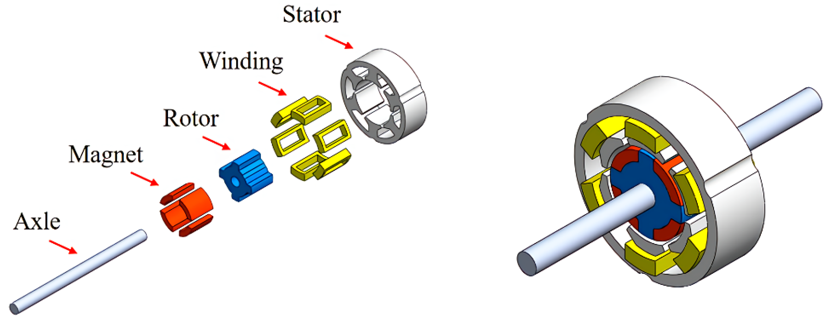
2.1. Inset Permanent Magnet Synchronous Motors Design
The micro inset motor was designed with a six-slot stator and a four-pole rotor. The stator had an external diameter of 15 mm, an internal diameter of 8.2 mm, and stack length of 5 mm. The rotor had an external diameter of 7.4 mm, root diameter 5.4 mm and an internal diameter of 2 mm. The tile-type permanent magnets were made of sintered NdFeB, grade N48H (Teslar Technology Co., Ltd., Taichung, Taiwan) with radial magnetization. The thickness of the permanent magnet was limited to 1 mm by the manufacturer. Each winding coil had a total of 60 turns and resistance of 2.65 Ω. Table 1 lists the design specifications of the inset permanent magnet synchronous motor. Figure 1 shows the exploded view and assembly drawing of the inset motor.
Table 1.
Design specifications of the inset permanent magnet synchronous motor.
Figure 1.
Exploded view and assembly drawing of the inset permanent magnet synchronous motor.
To demonstrate the feasibility of powder sintering the SMC material, the micro inset motors were developed using two different soft magnetic materials: a silicon steel sheet (35CS300) (China Steel Corporation, Kaohsiung, Taiwan) and Somaloy 700 1P (Högnäs AB, Bruksgatan, Sweden). The magnetization curves of both materials are shown in Figure 2.
Figure 2.
Magnetization curves of silicon steel (35CS300) and Somaloy 700 1P.
2.2. Rotor Design of the Inset Permanent Magnet Synchronous Motor
The design parameters of the inset motor were fixed for this study, allowing variation only in the interpole iron width of the rotor. Figure 3 shows an illustration of the inset magnet rotor. There was no air gap between the interpole iron and the permanent magnet. The surface-mounted motor was a special case where the interpole iron width was set to zero.
Figure 3.
Illustration of the inset magnet rotor.
The 2D electromagnetic analysis of inset motors was determined using JMAG finite element analysis software developed by the JSOL Corporation, Tokyo, Japan. Various motor designs were evaluated with the interpole iron width ranging from 0 mm to 2 mm. The analytical models assumed that the motors were made of silicon steel (35CS300) and driven by the single-phase square wave current of 1 A at a rotational speed of 1000 RPM under a no-load condition. The final motor design was chosen based on its high torque density and low torque ripple.
Torque ripple (Tripple) was defined as
where Tmax, Tmin, and Tavg are the maximum, minimum, and average torques, respectively.
Torque density (TV) was defined as
where Vol is the volume of the magnet.
The preliminary analysis of the motor designs was assessed with interpole iron widths of 0, 0.5, 1, 1.5, and 2 mm, as shown in Figure 4. The torque characteristics and volume of the magnet were obtained as shown in Table 2. The best design can be found in the interpole iron widths between 1 mm and 2 mm.
Figure 4.
Motor designs with various interpole iron widths.
Table 2.
Motor characteristics with interpole iron widths of 0, 0.5, 1, 1.5, and 2 mm.
To find the final motor design, further analysis was conducted with interpole iron widths changing from 1.1 mm to 1.9 mm in increments of 0.1 mm. The motor characteristics were calculated as shown in Table 3. The final design was selected with an interpole iron width of 1.6 mm. The motor had an average torque of 3.008 mN-m, a torque ripple of 74.77%, and a torque density of 0.172 mN-m/mm3.
Table 3.
Motor characteristics with interpole iron widths between 1.1 mm and 1.9 mm.
2.3. Electromagnetic Analysis of Inset Permanent Magnet Synchronous Motor
The performances of the inset motors were analyzed using both silicon steel 35CS300 and Somaloy 700 1P materials for comparison. The output torque was calculated at a single-phase square wave current input of 1 A at rotational speed of 1000 RPM under a no-load condition. Figure 5 shows the torque-angle curves of the silicon steel and SMC motors. The silicon steel motor had an average torque of 3.01 mN-m and torque ripple of 74.8%. The SMC motor had an average torque of 2.73 mN-m and torque ripple of 64.4%. The BEMF was computed at a rotational speed of 9000 RPM. Figure 6a,b shows the BEMF-angle curves for the two motors. The BEMF of the silicon steel and SMC motors is 3.77 V and 3.34 V, respectively. The motor characteristics are summarized in Table 4.
Figure 5.
Torque-angle curves of 35CS300 and Somaloy 700 1P motors at an input current of 1 A.
Figure 6.
BEMF-angle curves of (a) 35CS300 and (b) Somaloy 700 1P motors at a rotational speed of 9000 RPM.
Table 4.
Theoretical properties of 35CS300 and Somaloy 700 1P motors.
The performance of the SMC motor was poorer than that of the silicon steel motor because of its lower saturation magnetic flux density and permeability. The maximum torque of the silicon steel motor occurred at a 94° angle and the magnetic flux density distribution is shown in Figure 7a. Magnetic saturation occurred at the tooth and yoke of the stator since the maximum flux density of 1.72 T was higher than the saturation magnetic flux density of 1.63 T for 35CS300. The maximum torque of the SMC motor occurred at an 86° angle and the magnetic flux density distribution is shown in Figure 7b. There was also magnetic saturation in this case because the maximum flux density of 1.75 T was higher than the saturation magnetic flux density of 1.31 T for Somaloy 700 1P. If the geometries of the stator are redesigned, the magnetic saturation problem in the motors will be resolved.
Figure 7.
Magnetic flux density distributions of (a) 35CS300 and (b) Somaloy 700 1P motors at maximum torques.
2.4. Improved Designs of Inset Permanent Magnet Synchronous Motors
The magnetic saturation problem of two motors can be solved by increasing the cross-sectional areas and chamfers in the yoke and tooth. The performance of the SMC motor was further enhanced by changing the soft magnet material to Somaloy 1000 3P. The stator of the silicon steel motor was redesigned with an external diameter of 15.5 mm, a yoke width of 1.3 mm, and a tooth width of 2.5 mm. The maximum torque of the silicon steel motor occurred at a 97° angle and the magnetic flux density distribution is shown in Figure 8a. The stator of the SMC motor was redesigned with an external diameter of 15.5 mm, a yoke width of 1.4 mm, and a tooth width of 2.7 mm. The maximum torque of the SMC motor occurred at a 97° angle and the magnetic flux density distribution is shown in Figure 8b. The motor characteristics of the improved designs are summarized in Table 5. The average torque, torque ripple, and BEMF all increased without magnetic saturation. However, the final designs of the two motors are unchanged and the same as shown in Table 1, to demonstrate the performance difference of the two soft magnet materials.
Figure 8.
Magnetic flux density distributions of (a) 35CS300 and (b) Somaloy 1000 3P in improved motor designs at maximum torques.
Table 5.
Theoretical properties of 35CS300 and Somaloy 1000 3P motors.
3. Fabrication and Assembly of Inset Permanent Magnet Synchronous Motors
3.1. Fabrication of Motor Stator and Rotor
The two micro inset motors were made from different soft magnetic materials—silicon steel (35CS300) and Somaloy 700 1P. The silicon steel sheets were cut by wire electrical discharge machining (WEDM) and stacked together to form the laminated cores of the stator and rotor as shown in Figure 9a. The SMC cores were first sintered and heat-treated, and then machined by WEDM to obtain the final shapes of the stator and rotor as shown in Figure 9b.
Figure 9.
Stator and rotor cores made of (a) 35CS300 and (b) Somaloy 700 1P.
3.2. Motor Assembly
Before assembly, the dimensions of the motor parts had to be checked to ensure that they met design specifications. The precision and concentricity of the axial shaft, stator, and rotor are critical to reduce motor vibration. The stator slot was insulated with tape before the coils were wound manually. The motor was assembled with an end frame, bearing, stator core, axial shaft, and rotor, and a bearing and frame on the other side. Pictures of the mechanical parts and assembled motors are shown in Figure 10 and Figure 11.
Figure 10.
Mechanical parts of (a) 35CS300 and (b) Somaloy 700 1P motors.
Figure 11.
Assembled motors made of (a) 35CS300 and (b) Somaloy 700 1P.
4. Properties Testing of Inset Permanent Magnet Synchronous Motors
4.1. Motor Speed Testing
The speed of the motors was measured using the square wave current drive and the voltage and current signals of the winding coil were measured at various excitation frequencies. At a rated current of 1 A, the maximum rotational speed of the motor was 9000 RPM at an excitation frequency of 300 Hz. The voltage and current signals of the motors made of silicon steel (35CS300) and Somaloy 700 1P cores are shown in Figure 12a,b.
Figure 12.
Voltage and current signals of (a) 35CS300 and (b) Somaloy 700 1P motors at a rotational speed of 9000 RPM.
4.2. Motor Torque Testing
The experimental torque was measured by hanging standard test weights on the external diameter of the rotor at every 10° interval from 0° to 60°. The torque-current curves were tested at currents from 0.5 A to 1 A in increments of 0.1 A. The motor friction torque was estimated to be 0.08 mN-m using a minimum starting current of 0.035 A and then used to calculate actual output torques. At a rated current of 1 A, the average torques for the silicon steel and SMC motors were 2.55 mN-m and 2.35 mN-m, respectively, after friction compensation. The torque constants (KT) were 2.59 mN-m/A and 2.37 mN-m/A, respectively. The theoretical and experimental KT of the two motors are compared in Table 6. Lastly, the theoretical and experimental torque-current curves are plotted as shown in Figure 13. The errors between the theoretical and experimental KT of the silicon steel and SMC motors were −13.1% and −12.5%, respectively. The experimental KT of the SMC motor was 8.5% less than that of the silicon steel motor.
Table 6.
Comparison of torque constants (KT) of 35CS300 and Somaloy 700 1P motors.
Figure 13.
Torque-current curves of 35CS300 and Somaloy 700 1P motors.
4.3. Motor BEMF Testing
The experimental BEMF was tested using a micro-dynamometer (HSY. Co., Ltd., Taichung, Taiwan) at every 2000 RPM interval from 1000 to 9000 RPM. At a rotational speed of 9000 RPM, the BEMF for the silicon steel and SMC motors was 3.24 V and 2.96 V, respectively. The BEMF constants (KV) were 3.50 mV/(rad/s) and 3.08 mV/(rad/s), respectively. The theoretical and experimental KV of the two motors are compared in Table 7 and voltage-speed curves are plotted as shown in Figure 14. The error between the theoretical and experimental KV of the silicon steel and SMC motors was −12.7% and −13.7%, respectively. The experimental KV of SMC motor was 12.0% less than that of silicon steel motor.
Table 7.
Comparison of BEMF constants (KV) of 35CS300 and Somaloy 700 1P motors.
Figure 14.
Voltage-speed curves of 35CS300 and Somaloy 700 1P motors.
4.4. Discussion
The experimental performance of the micro inset motor using Somaloy 700 1P was worse than that of silicon steel (35CS300). Its torque constant (KT) and BEMF constant (KV) were 8.5% and 12.0% lower, respectively. There were two reasons for this: the saturation magnetic flux density and magnetic permeability of the Somaloy material were inferior, and there was magnetic saturation occurring at the stator yoke and tooth. However, the powder sintered SMC material allows for mass-production and near-net-shape manufacturing without assembly, which saves time and reduces the cost of micromotors. This study demonstrated the feasibility of the inset SMC micromotor, which can achieve the performance of a commercial BLDC motor such as Faulhaber 1509T006B. The inset motor can be further improved by motor design optimization based on Somaloy 1000 3P and SMC magnetic property advancement in the future.
5. Conclusions
In this study, a six-slot stator and a four-pole micro inset permanent magnet motor was developed with an external diameter of 15 mm and a length of 5 mm. The miniaturization of the motor is currently limited by a 1 mm thick rare earth tile-type permanent magnet. The inset motors were fabricated and tested using two different core materials, silicon steel and soft magnetic composite (SMC). Although the motor performance using silicon steel was better, the SMC core can be easily made without lamination, which is particularly suitable for micromotors. At an input square wave current of 1 A, two motors achieved a stall torque over 2.35 mN-m and a maximum speed of 9000 RPM. Experimental testing found that both motors meet the specifications of commercial motors used for small robots, portable hand-held power tools, micro pumps, and surveillance camera systems.
Author Contributions
Conceptualization, D.-C.P.; methodology, D.-C.P.; validation, D.-C.P., Z.-J.S., P.-X.X., H.-C.H., and G.-T.B.; formal analysis, D.-C.P., Z.-J.S., P.-X.X. and G.-T.B.; investigation, D.-C.P., Z.-J.S., P.-X.X., H.-C.H., and G.-T.B.; data curation, D.-C.P., Z.-J.S., P.-X.X.; writing—original draft preparation, D.-C.P., Z.-J.S., P.-X.X.; writing—review and editing, D.-C.P., H.-C.H. and G.-T.B.; supervision, D.-C.P. All authors have read and agreed to the published version of the manuscript.
Funding
This work was partially funded by the MEMS and Precision Machinery Research and Development Center and the Department of Mechanical Engineering at National Kaohsiung University of Science and Technology.
Conflicts of Interest
The authors declare no conflict of interest.
References
- Rahideh, A.; Korakianitis, T. Analytical Magnetic Field Distribution of Slotless Brushless Machines with Inset Permanent Magnets. IEEE Trans. Magn. 2011, 47, 1763–1774. [Google Scholar] [CrossRef]
- Zhao, W.; Lipo, T.A.; Kwon, B. Optimal Design of a Novel Asymmetrical Rotor Structure to Obtain Torque and Efficiency Improvement in Surface Inset PM Motors. IEEE Trans. Magn. 2015, 51, 1–4. [Google Scholar]
- Boroujeni, S.T.; Emami, S.P.; Jalali, P. Analytical modeling of eccentric PM-inset machines with a slotless armature. IEEE Trans. Energy Convers. 2019, 34, 1466–1474. [Google Scholar] [CrossRef]
- Qu, B.; Yang, Q.; Li, Y.; Sotelo, M.A.; Ma, S.; Li, Z. A Novel Surface Inset Permanent Magnet Synchronous Motor for Electric Vehicles. Symmetry 2020, 12, 179. [Google Scholar] [CrossRef]
- Haraguchi, H.; Morimoto, S.; Sanada, M. Suitable design of a PMSG for a large-scale wind power generator. In Proceedings of the 2009 IEEE Energy Conversion Congress and Exposition, San Jose, CA, USA, 20–24 September 2009. [Google Scholar]
- Boztas, G.; Aydogmus, O. Design of a High-Speed PMSM for Flywheel Systems. In Proceedings of the 2019 4th International Conference on Power Electronics and Their Applications (ICPEA), Elazig, Turkey, 25–27 September 2019. [Google Scholar]
- Hwang, C.C.; Liu, C.T.; Teng, C.C. Design and analysis of a novel inset permanent magnet synchronous motor. J. Magn. Magn. Mater. 2008, 320, e283–e286. [Google Scholar] [CrossRef]
- Büttgenbach, S. Electromagnetic Micromotors—Design, Fabrication and Applications. Micromachines 2014, 5, 929–942. [Google Scholar] [CrossRef]
- Pang, D.C.; Lai, Y.W. Rapid Prototyping of a Micromotor with an Optical Rotary Encoder. Micromachines 2017, 8, 174. [Google Scholar]
- Persson, M.; Jansson, P.; Jack, A.G.; Mecrow, B.C. Soft magnetic composite materials-use for electrical machines. In Proceedings of the 1995 Seventh International Conference on Electrical Machines and Drives (Conf. Publ. No. 412), Durham, UK, 11–13 September 1995. [Google Scholar]
- Shokrollahi, H.; Janghorban, K. Soft magnetic composite materials (SMCs). J. Mater. Process. Technol. 2007, 189, 1–12. [Google Scholar] [CrossRef]
- Somaloy, Powders for Electromagnetic Applications. Available online: https://www.hoganas.com/en/powder-technologies/soft-magnetic-composites/products/coated-powders-for-electromagnetic-applications (accessed on 9 July 2020).
- Anderson, O.; Hofecker, P. Advances in soft magnetic composites—Materials and applications. In Proceedings of the PowderMet2009, Las Vegas, NV, USA, 1 July 2009. [Google Scholar]
- Wang, B.; Xu, Y.; Xu, L.; Xin, F. A novel PMSM with 3-dimensional magnetic circuit using SMC core. In Proceedings of the 2017 IEEE Transportation Electrification Conference and Expo, Asia-Pacific (ITEC Asia-Pacific), Harbin, China, 7–10 August 2017. [Google Scholar]
- Guo, Y.G.; Zhu, J.G.; Watterson, P.A.; Holliday, W.M.; Wu, W. Improved design and performance analysis of a claw pole permanent SMC motor with sensorless brushless DC drive. In Proceedings of the Fifth International Conference on Power Electronics and Drive Systems (PEDS), Singapore, 17–20 November 2003. [Google Scholar]
- Doering, J.; Steinborn, G.; Hofmann, W. Torque, power, losses, and heat calculation of a transverse flux reluctance machine with soft magnetic composite materials and disk-shaped rotor. IEEE Trans. Ind. Appl. 2015, 51, 1494–1504. [Google Scholar] [CrossRef]
- Morimoto, M. Induction motor made of iron powder core. In Proceedings of the 2009 13th European Conference on Power Electronics and Applications, Barcelona, Spain, 21–24 June 2010. [Google Scholar]
- Kim, C.W.; Jang, G.H.; Kim, J.M.; Ahn, J.H.; Baek, C.H.; Choi, J.Y. Comparison of Axial Flux Permanent Magnet Synchronous Machines With Electrical Steel Core and Soft Magnetic Composite Core. IEEE Trans. Magn. 2017, 53, 1–4. [Google Scholar] [CrossRef]
- Marignetti, F.; Colli, V.D.; Carbone, S. Comparison of Axial Flux PM Synchronous Machines With Different Rotor Back Cores. IEEE Trans. Magn. 2010, 46, 598–601. [Google Scholar] [CrossRef]
- Ishikawa, T.; Sato, Y.; Kurita, N. Performance of Novel Permanent Magnet Synchronous Machines Made of Soft Magnetic Composite Core. IEEE Trans. Magn. 2014, 50, 1–4. [Google Scholar] [CrossRef]
- Deodhar, R.P.; Pride, A.; Bremner, J.J. Design Method and Experimental Verification of a Novel Technique for Torque Ripple Reduction in Stator Claw-Pole PM Machines. IEEE Trans. Ind. Appl. 2015, 51, 3743–3750. [Google Scholar] [CrossRef]
- Liu, C.; Lei, G.; Ma, B.; Guo, Y.; Zhu, J. Robust Design of a Low-Cost Permanent Magnet Motor with Soft Magnetic Composite Cores Considering the Manufacturing Process and Tolerances. Energies 2018, 11, 2025. [Google Scholar] [CrossRef]
- Wang, X.; Zhou, S.; Wu, L.; Zhao, M.; Hu, C. Iron Loss and Thermal Analysis of High Speed PM motor Using Soft Magnetic Composite Material. In Proceedings of the 2019 22nd International Conference on Electrical Machines and Systems (ICEMS), Harbin, China, 11–14 August 2019. [Google Scholar]
© 2020 by the authors. Licensee MDPI, Basel, Switzerland. This article is an open access article distributed under the terms and conditions of the Creative Commons Attribution (CC BY) license (http://creativecommons.org/licenses/by/4.0/).