Abstract
Nowadays, the reduction of aircraft emissions is one of the industrial targets with a horizon time until 2050. The recent progresses in electrical drives give the opportunity to modify the aircraft propulsion based on thermal engine or gas turbine to a hybrid/full electric one. Some problems must be solved: weight, reliability, and the choice of the best configuration for the electric propulsion. One of the most important aspects to solve is the thermal behavior of power converters and electric motors. This paper proposes an optimization procedure for the design of surface permanent magnet motors used for the aircraft propulsion: the aim of the paper is to investigate the possibility of cooling the motor with only the air flow due to the aircraft speed. The optimization procedure has been solved with the integration of analytical model and finite element analysis and using a differential evolution algorithm.
1. Introduction
The rapid growing of civil air traffic in last decades determined the start of different initiatives [1] with the aim to reduce aircraft emissions in the atmosphere. Considering that the greatest part of aircraft emissions happens during the phase of take-off and climb, this is also strictly related to the livability of a city which is often close to the airport. The major contribute of some international researches concerns the reduction of noise emission and the reduction of CO2 and other type of pollutants. In the field of aerospace, the first electrification step started with the concept of more electric aircraft [2], where some hydraulic flight systems were substituted with full electric or electro-hydraulic systems with the aim to increase the efficiency and reliability of the overall system. The recent progresses in electrical machines and power electronics have allowed to increases in power density, safety, and the reliability of the electrical drives. These advancements give the possibility to consider a full electric/hybrid propulsion system in civil aviation. This paper is focused on the electric propulsion of unmanned aerial vehicles, adopted for civil application, and in particular on the sizing of propulsion motors. Many research projects propose the use of full electric propulsion [3] or hybrid electric propulsion [4] in these kinds of aerial vehicles. Now, the energy storage systems appear to be the most limiting technologies for the electric propulsion, but the interests of researchers are now focused on the development of new battery technologies [5,6] and in the use of some optimization procedure for the weight reduction of optimization distribution of energy storage systems [7,8,9,10]. Regarding the electrical machine, recent investigations propose the design and development of on-board generation machines, and propulsion electric motors. The researches [11] are carried out with the goal to increase the power density, the reliability and the efficiency. Many types of electrical machines are considered: induction motor [12,13], permanent magnet synchronous motor [14] (the most utilized), and traditional synchronous machine above all with superconducting characteristics [15,16].
One of the critical aspects of the electrical machine is related to the cooling. The necessity to reach high values of power density involves the use of a liquid cooling system. Due to many factors, in aerospace applications the liquid cooling is a delicate system to size because the increased volume occupation, reduction of reliability, and danger of liquid freezing. An alternative to the liquid cooling could be the use of forced convection due to the air flow generated by the aircraft speed and the propellers; obviously, this determines a reduction of power density but with an overall increase of reliability and reduction of the on-board volume occupation. In this paper is proposed a design methodology able to investigate the use of forced convection due to the air flow for electric motors used for the propulsion of hybrid/full electric aircraft. Typical approaches presented in literature [17,18,19] provide the design and the analysis of electric motors using a multiphysics approach based on magneto-thermal analysis. In this case the thermal analyses are carried out using high and low order in a lumped parameters method, with a reduction of computation time but also with an increase in the error of temperature estimation. A coupled magneto-thermal sizing procedure based on finite element analysis is presented in this paper. To reduce the computational cost of thermal analysis, a discretization of the 3D domain in many 2D analyses is proposed.
The approach starts from the solution of heat problem for the calculation of an appropriate heat exchange coefficient and using the magneto-thermal finite element analysis, a sizing methodology for forced air cooled motor is developed. The optimal sizing procedure is solved using a differential evolution algorithm.
2. Electric Aircraft Propulsion: Thermal Considerations
The electric motors and the power converters used for aircraft application must satisfy specific requirements due to the extreme environment conditions. According to the military standards MIL-STD-810H [20] and to other civil standards, the operating range temperature for an aerospace component must be in the range –55 °C–75 °C. This temperature interval implies the necessity to introduce an accurate design methodology and to find an optimal trade-off condition between the reliability, the weight, and the efficiency of the components. A great impact is related to the type of cooling systems adopted for the electrical components. As previously mentioned and regarding the electric motors, recent progresses in aircraft electric propulsion show the use of liquid cooling machines [21], able to guarantee very high value of power density (kW/kg). For a large range of temperatures, the liquid cooling also gives the possibility of reducing the dependence between the external ambient temperature and the cooling efficiency of the electrical machine. The main problems related to the liquid cooling are inherent:
- -
- the reduction of the overall reliability due to the use of radiator, pipeline, valves, and pumps; besides, it is necessary to highlight that the complete fault of liquid cooling system determines the complete or quasi complete reduction of the electrical drive’s performance;
- -
- increase of volume occupation inside the aircraft due to the necessity to install the previous mentioned devices;
- -
- safety problems: the liquid used for the cooling system must guarantee a low fire hazard and the cooling properties in the whole temperature range.
A possible solution to avoid the use of liquid cooling systems could be the use of external force convection, that in aerospace propulsion can be generated through the aircraft speed and propeller movement. The heat coefficient transfer due to the air movement depends on the air speed and the angular speed of the propeller, but also on the external temperature condition. In fact, the air temperature influences the greatest part of air properties and specifically the mass density. Moreover, the air temperature, Tair, is strictly related to the altitude, according to the following linear relation:
where z is the altitude and ks is the lapse rate equal to 0.0065 (°C/m). The relation air temperature–altitude determines a variation of cooling effect during the different phase of flight and a correct evaluation of the heat transfer coefficient is required by an optimal sizing procedure.
The electric motor adopted for the aircraft propulsion is positioned behind the propeller and with an axis of limited length. The air flow due to aircraft speed (to simplify the approach, the wind speed is not considered) passes through the propeller: this passage determines an increase of the air flow speed due to the propeller movement. The calculation of the correct air flow speed is carried out using the single impulsive theory, where the air flow is considered in steady state condition, irrotational, and ideal.
The propeller is considered as an actuator disk, which is a disk with infinitesimal thickness. The thrust is uniformly distributed along the disk and during the rotation, an instantaneous pressure variation acts through the disk. With the ideal condition that no air stream rotations are introduced by the disk, is obtained that the pressure at the Point 1 is equal to the pressure in the Point 2 [22]. Using the concept of flux tube, the thrust on the disk can be calculated in two ways:
- (1)
- applying Bernoulli’s equation to the different sections of Figure 1. In fact, it is possible to write Bernoulli’s equation for the front face of the disk:and for the back face:
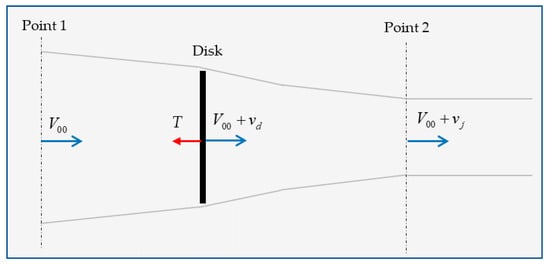 Figure 1. Single impulsive theory model adopted for the air flow calculation along the electric motor.In (2) and (3), is the air density, V00 is the air flow speed, vd is the induced speed by the propeller and vj is the increased of airflow speed in the Section 2 (which is ideally located very distant). The p00, pff, and pbf are the pressions at the Point 1 (equal to the point2) and at the front and back face of the disk.The difference between relations (3) and (2) gives the pressure drop on the disk:From relation (4), if the pressure drop Δp is constant along the disk, it is possible to calculate the thrust vector T, using the equation:where Ad is the frontal area of the propeller;
 - (2)
- A second method for the calculation of the thrust T is based on the use of variation of the momentum M (kgms−1) between Point 1 and Point 2. With the equality of the pressure in these two points, the thrust is calculated as:where is the mass flow inside the tube of flux. The expression of the mass flow at the disk stage is:
Therefore, joining the (6) with the (7), the following thrust formula is determined:
Comparing the two-equivalent expressions (5) and (8), it is easy to note that the increase of speed due to the disk is the half of the speed increase at infinity (Point 2):
Analyzing Equation (5) or Equation (8) and according to the thrust sign in Figure 1, it is highlighted that the air flux speed backward from the propellers is increased, with an improvement of the cooling efficiency for the mover of the propeller, as the electric motor. The speed increase can be easily determined starting from the value of thrust and using relations (5) or (8) together with the formula (9). The thrust is determined using the mechanical power of the propellers and the speed V00, which is assumed equal to the aircraft speed.
As is well-known, the external surface of the motor is heated by three different heat fluxes, determining that the heat flux is not constant along the external motor surface: two heat fluxes are related to the end-winding’s losses, the other one is the heat flux due to the windings located in the slots and the iron losses. Usually, the end-windings of the most common electrical machines are cooled through natural convection and therefore they become one of the critical parts. In traction or propulsion applications, it is preferable to put a resin around the end-windings [23,24], with the aim of conducting the heat through the resin to the external surface, where a liquid cooling jacket or an external free stream provide the removal of the heat.
In the paper, the heat exchange problem of the propulsion motor is approached with the case of constant free-stream velocity flow along a semi-infinite plate (located along the longitudinal axis of the cylinder), subjected to a variable surface heat flux [25]. In this case, the rise of surface temperature at length L can be derived by:
where T00 is the temperature of the air flow, k is the thermal conductivity of the air (W/(m K)), is the heat flux distribution along the surface (W/m2), and Pr and ReL are the Prandtl and Reynolds numbers defined as:
where L is the length of the motor, cp is the specific heat coefficient of the air (J/(kg K)), and µc and µd are the air kinematic viscosity (m2/s) and dynamic viscosity(kg/(m s)). Due to the limited length of the motor, the air speed is considered constant and equal to the air speed downstream of the disk (V00 + vd). For the correct calculation of (12) and (13), the dependence of the parameters cp, k, µc, and µd by the pressure and temperature is considered, using the available data from literature [26]. The heat flux is due to the heat exchange determined by the motor losses through the motor surface and changes between the end-winding regions and the magnetic stack length. The evaluation of losses and thus of heat flux is presented in the next chapter. The rise of temperature described by Equations (10) and (11) is computed using the trapezoidal method to solve the integral. The heat exchange coefficients are related to the Nusselt number, which can be computed as:
These values can be used in a thermal finite element analysis, where the following equation must be solved:
Imposing an appropriate boundary convection condition on the external surface (the symbol indicates the gradient) through the calculated heat transfer coefficient h and the flux stream temperature T00.
3. Optimal Design of Propulsion Electric Motor
As previously described, the design of a propulsion motor for hybrid/full electric aircraft is quite complex with respect to an industrial motor for the thermal problem and the necessity to reduce the weight. The greatest part of the propellers used in aircraft have a hydraulic system able to modify the angle pitch and keep the angular speed of the propeller constant. The constant speed (or a strict variation speed range) is an advantage in the design of propulsion motors with respect to the traction application [27] where a good performance in terms of efficiency must be guaranteed in a large range of angular speeds. The optimal solution for a propulsion motor can be obtained using a multiphysics approach, able to merge the magnetic and thermal problems at the same time. A precise and affordable solution can be obtained with finite element analysis (FEA), both for the magnetic and thermal analyses. As it is well-known, the FEA needs a high computational cost and a large simulation time, but it is feasible for solving an optimization problem by means of heuristic optimizations able to reduce the number of iterations required for the evaluation of a cost function under given constraints. One of the most adopted methods is based on the differential evolution (DE) algorithm [28], which is proposed in many variants and used in the field of electrical machines [29,30]. The DE algorithm starts from an initial population of a certain number of electric motors with similar characteristics, which can be generated randomly or using the value of existing motors. In our cases a mixed method is applied. Starting from an existing electric motor with the same rated speed and with a similar rated power, and self-ventilated cooling. As it will be shown in the next paragraph, the proposed optimal design methodology is based on a low number of considered design variables. This is due to the necessity of reducing the computational cost: therefore, the use of some characteristics inherited from existing machines appears necessary. In particular the magnetic stack length, the magnet pole arc, the number of slots (Q), and the number of turns per pole and per phase (Ns,p) are maintained fixed and extracted from the existing motor.
3.1. Determination of Initial Population
The initial population is generated following the next steps:
(Step 1) Using the main parameters of an electric motor of rated power P and rated angular speed ωr,n the external rotor diameter Dr,e, the current density in the conductor J, the rated current In, and permanent magnet length hm are chosen as random variables:
In Equations (17)–(20), the functions unifrndint and unifrnd generate a random integer number (lower than np, which indicates the number of population elements) and a real random number (lower than 1) using a uniform distribution. The ranges , , , and could be chosen or with the use of analytical formulation or through some initial simulations able to find an opportune maximum value of the parameters. The latter solution is adopted in the paper.
The decision to consider as random variables both the current density and the rated current of the machine comes from the necessity to find possible solutions which satisfy both the thermal problem and voltage limits: It is necessary to highlight that with respect to the voltage limits, in aerospace propulsion it could be quite difficult to satisfy due to the limited value of DC bus voltage (in our case it is considered the value of 270 V), mainly when the requested speed and power are high.
The check of voltage limits passes through the calculation of the back-emf and the synchronous inductance of the motor. The back-emf is calculated by means of Faraday’s law and determining the rotor linkage flux Φr. For a 2D finite element analysis, the rotor linkage flux with a single-phase coil is calculated as [31,32]:
where Ss is the slot area, A(z) is the z-component of the potential vector of magnetic flux density, and L is the stack length of the machine. The integral in (21) is numerically computed on both forward (sf) and backward (sb) sides of the phase coils. The derivative versus time of expression (21) provides the back-emf
From a sizing point of view, two variables act on the variation of the back-emf value: the rotor diameter and the permanent magnet length.
The value of synchronous inductance Ls is calculated with the knowledge of the electromagnetic energy Emot in the airgap and in the slots [31,32]. Considering the permanent magnet without the magnetization, the Emot can be determined by imposing a quadrature axis current of amplitude In and using the following relations: (it was verified that with a d-axis current, the value of mutual inductance of the considered motor is the same).
For the machine with a superficial permanent magnet, it is often verified that the direct and quadrature axis inductances are very similar. Therefore, only the computation of Ls with the quadrature current axis has been performed.
(Step 2) In the second step the complete sizing of the motor is carried out.
(Step 2.1) Therefore, the determination of conductor area Sc, the stator () and rotor () yokes are carried out using the formula proposed in [33,34]:
where p is the number of pole pairs, g is air gap length, Bg, By,s and By,r are the maximum values of magnetic flux density in the air-gap, stator yoke, and rotor yoke.
(Step 2.2) The number of pole pairs is chosen as the possible higher number according to the optimal frequency of the converter (fconv) and the maximum speed of the motor. As previously mentioned, the range variation speed in the proposed application is very tight, and the maximum speed equal to the rated speed (ωr,n) of the motor can be imposed. From this, the number of pole pairs is calculated as:
In our case, the number of pole pairs is equal to the pole pairs of the initial motor parameters using for the generation of population. If this value was different, a new reconfiguration of windings and of the number of slots should be necessary, with an increase in the number of unknown variables.
(Step 2.3) The air-gap length is calculated starting from the optimization variable hm and imposing an opportune value of maximum flux density in the air gap Bg,max (in this paper is imposed equal to 0.8 T). In particular for a PMSM with sinusoidal air gap flux density, the air gap length is obtained as [35]:
where Br is the residual flux density of the magnet at the design temperature.
(Step 2.4) The slot height depends on:
- -
- the insulation thickness between two conductors is,c and the thickness of the film between the coils and the slot is,k
- -
- the slot opening length ac;
- -
- the slot opening height pc;
- -
- the wedge thickness bc;
- -
- the insulation between two different layers il;
- -
- the fill factor kcu fixed to 0.60;
- -
- the number of conductors in the slots and their main sizes hc and lc. The dimension of the conductor is obtained from the area Sc using the dimension available from the commercial catalogue. The lc is always selected so that:
- -
- the slot edge;
In our case, an open rectangular slot with bar conductors is considered and shown in Figure 2:
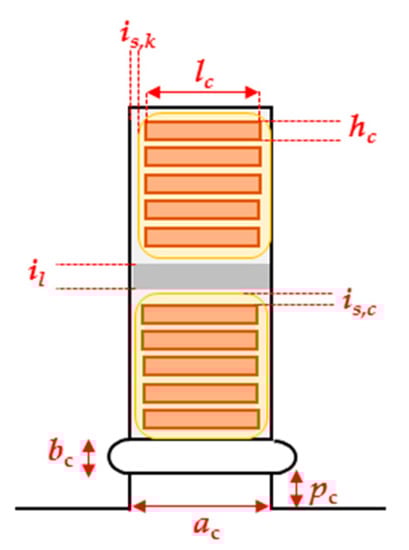
Figure 2.
Slot edge and parameters adopted for the slot dimensions.
The slot height is determined using the following relations and the feasibility of the slot is verified through the realization of 2D CAD in the pre-processing of finite element analysis.
The parameters is,c, is,k, and il depend on the type of insulation and their values are below 1 mm. The wedge thickness and the slot opening are not modified with respect to the reference motor, and in our case are both 1 mm. Besides the ac depends on the internal diameter of the motor (equal to ) and by the maximum value of magnetic flux density inside the tooth.
In the presented paper, two different sizings are carried out and will be presented in Section 3.2:
- (a)
- the first one with conservative values of magnetic flux density peaks in the iron are used in the paper (1.4 T in the tooth, Bt, and 1.1 T in the rotor and stator yokes). This is due to the necessity of reducing the iron losses and guarantees an overloadability of the motor; this aspect is not treated in this paper and will be the topic of further investigations.
- (b)
- In the latter sizing procedure the values of 1.7 T in the tooth and 1.5 T in the yokes are adopted.
(Step 2.5) End windings’ mass calculations: the length of the end winding of the motor is obtained with the approximated formula:
Figure 3 shows a linearization of the machine and of the end-windings.
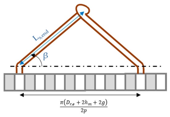
Figure 3.
Linearized machine and end windings.
The angle β also depends on the manufacturer’s quality and in our case is fixed at 45°. A safety factor of 1.2 is adopted in the calculation. The mass of the end windings are calculated as:
where Ncc is the number of conductors per slot, Q is the number of slots, and is the mass density of copper (kg/m3). The weights of the resin and of the insulation are negligible with respect to the copper’s weight.
(Step 2.6) Calculation of total mass: the total mass of the motor is the sum of the mass of the end windings, the mass of the active windings, and the iron part. The mass of the end windings is calculated with relation (30), while the active winding mass and the iron part’s mass are calculated by evaluating the volume from the 2D CAD of the motor.
(Step 3) The motor obtained with the processes in Steps 1 and 2 is analyzed by means of a magnetostatic FEA. The outputs of the analysis are the rated electromagnetic torque, the back-emf at the rated speed, and the synchronous inductance of the machine. With the AC magnetostatic analysis it is also possible to compute the iron losses and the joule losses in the conductors. For the iron losses, the five parameters formula is used [36]:
where the parameters Fskin, a1, a2, a3, a4, a5, and α depend on the adopted magnetic sheets and can be calculated from the specific curve losses of the material or through experimental tests; f is the supply frequency; and B is the magnetic flux density in the iron.
The joule losses in the conductor are calculated using the following relation:
where σ is the conductibility of the conductors and the distribution of current density in the conductor Jc(x,y,z) is calculated taking into account the skin effect of the conductor at the rated supply frequency. The current density Jc(x,y,z) (which become dependent only by z in 2D geometry) is obtained through the solution of the following equation:
which permits calculation of the current density distribution Jc = Jc(x,y,z) inside the conductor. Using the calculated current density, the numerical calculation of (32) on the conductor mesh, gives the total joule losses. In the proposed approach, the losses in permanent magnets are neglected.
The electromagnetic torque and the losses are used for the calculation of the rated power while the back-emf and the synchronous inductance are used for the verification of voltage limits. If the voltage limits are not satisfied, the variables (17–20) are discarded and a new iteration starts using another initial configuration (see Figure 2).
(Step 4) The last step for the generation of initial population is the verification of thermal limits. Using the Equations (14) and (15), the heat transfer coefficients are calculated for an altitude of 100 m and for an appropriate speed of air stream. The solution of thermal problem (16) with the FEA gives the temperature distribution in the main part of the motor. If the maximum temperatures satisfy the imposed maximum value in resin and in the windings, a new element of the initial population is found.
3.2. Optimization Problems
The sizing methodology proposed is applied in two different optimization problems: the first is a single objective problem and the second is a multi objective problem. For each problem, the initial populations have been generated using the procedure explained in Section 3.1. The objective functions are inherent in the following:
| Problem 1 | Problem 2 |
subject to the following inequalities constraints:
Mechanical constraint:
| Problem 1 | Problem 2 |
where Pmin and Pmax are the lower and upper limit allowed for the rated power of the motor
Magnetic constraints:
| Problem 1 | Problem 2 | |
| Bt | 1.4 T | 1.7 T |
| By,s, By,r | 1.1 T | 1.5 T |
Electrical constraints:
Due to the integration of optimization problems with FEA, all the equality constraints are transformed in inequalities, by means of the introduction of a range of variations, as it is shown for the mechanical constraints:
where ηtarget is the lower value of admissible efficiency, while Vl is the maximum value of supply voltage, Ls is the synchronous inductance, ωr,n is the angular speed, and is the linkage rotor flux.
Thermal constraints:
where Tend-wind and Twind are the maximum temperatures calculated though the 2D FEA in the end-windings and in the windings inside the magnetic stack, while Tmag is the maximum temperature in the magnets. The Tmax,wind and Tmax,mag are the limit temperatures imposed by the insulation class and the type of magnets adopted. In order to apply the 2D FEA, the length of the machine is divided into three parts; Figure 4: the two parts related to the end-windings (the first part x0–x1 is near the propeller, the other one is on the opposite side x2–x3) and the last part is the magnetic stack length (x1–x2). The three parts are further discretized with step Δx along the axial direction in order to consider the variation of heat exchange coefficient along the external surface. For each disk obtained, the local heat exchange coefficient is calculated according to the Nusselt number [14,15].
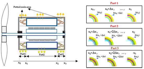
Figure 4.
Schematic of the motor: the end windings are immersed in a conductive resin; the yellow arrows show the heat flux transmission.
This procedure permits the reduction of computational cost with respect to the 3D analysis and gives a good precision compromises with respect to the 3D analysis, though the axial heat distribution is neglected.
The DE algorithm used is the type DE/rand/1/bin [28] (DE: differential evolution, rand: indicates that the individuals selected to compute the trial vectors are chosen as random variables, 1: is the number of pairs of the initial population chosen for the trial vector generation, bin: the binomial crossover is used) and the flowchart for the solution of the optimization problem is shown in Figure 5. Starting from the initial population, the random generation of a basic vector (or trial vector) is performed using the well-known formulas:
where the scale factor Fs has been chosen through numerical tests and the parameters r1, r2, and r3 are random integer numbers between 1 and the number of initial population elements.
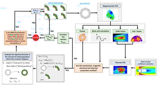
Figure 5.
Flowchart of the optimization problem solution by means of DE algorithm.
The “trial motor” is analyzed using magnetostatics and thermal FEA. With the magnetostatic analysis and according to the Section 3.1, the torque, the back-emf, and the losses in the conductor and in the iron have been calculated. The thermal finite element analysis is carried out at sea-level altitude, where the heat transfer coefficients have been calculated. If all the electrical and thermal constraints are verified and at the same time the crossover verification is positive, the obtained “trial motor” could modify the initial population. The “binomial” crossover check is a further stochastic element adopted in differential evolution able to simulate the biological evolution. It consists of the generation of two random numbers, one real and below 1, and the other (nrand) integer with maximum value np. A loop on the number of initial population np is started and if the real value is lower than the fixed crossover factor (fixed equal to 0.5 in the paper) or the index of the initial population element coincides with nrand, the check is satisfied. As previously cited, if the constraints and the crossover check are satisfied, the trial motor could be a candidate which can substitute the corresponding element of the initial population substituted with the crossover. In fact, if the value of the objective function is lower (or higher, depending on the optimization) than the objective function of the corresponding index in the initial population elements, the trial motor substitutes the element. Otherwise a new iteration with a new trial motor is performed. The algorithm is repeated for a certain number of substitutions of initial population elements and the adopted stopping criterion is the distribution-based criteria [37]. In particular, the optimization loop is closed when the difference between the best and the worst values of the objective function of the actual population is below a certain threshold mth. The threshold mth is imposed equal to a certain fraction of the difference between the best and worst values of the initial population. At the end, the optimal value is the minimum (maximum) value of objective function obtained in the population. The stop in the procedure could also happen under two other conditions:
- -
- the number of times when the constraints are not satisfied (indicated with the counter hconst) exceed the imposed limit itlim;
- -
- the number of times when no substitutions happen in the initial population (indicated with the counter hiter) exceed the imposed limit itlim;
These two conditions are usually related to an incorrect generation of initial population and DE parameters (e.g., the constant Fs). In the paper the number of itlim is imposed equal to two times the number of elements in the population.
4. Simulation Results and Discussion
The proposed approach is applied for the design of a propulsion motor used for an unmanned full electric aerial vehicle adopted for civil applications. In particular, Problem 1 is about the propulsion motor with a rated power of 60 kW and a rated speed of 3000 rpm which could be used in overspeed conditions and therefore, it is sized with a conservative value of magnetic flux density in the iron in order to reduce the losses. Problem 2 wants to maximize the power density and the maximum rated power which can be extracted with the imposed constraints. Both the motor are direct-drive linked to the propeller, without the use of any mechanical gears. The altitude range of the flight is 100–1000 m. The main desired features are reported in Table 1 for Problem 1 and Table 2 for Problem 2:

Table 1.
Desired motor characteristics Problem 1.
Table 2.
Desired motor characteristics Problem 2.
(Problem 1) The initial population contains thirty different motors which respect the characteristics in Table 1 and are generated according to the procedure in Section 3.1. The iterative solution of Section 3.2 is repeated until the number of substitutions in initial population is about 300 and the difference of the objective function value of the best and worst case is below 2.5% of the difference between the best and worst case of initial population. This value is assumed in order to impose that the mass variation is below 1 kg. Figure 6a–d shows the values of the optimization variables of initial population and the best value (red circle) obtained at the end of the optimization. The value of objective function (the total mass of the motor) is depicted in Figure 7. The optimization motor has a mass reduction of 4% with respect to the best value in the initial population; this low value is due in particular to the conservative design value adopted for the magnetic flux density in the iron parts and also for the conservative maximum values adopted for the temperature in the resin. All the parameters of the optimum motor are reported in Table 3.
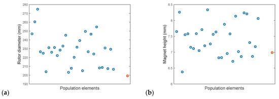
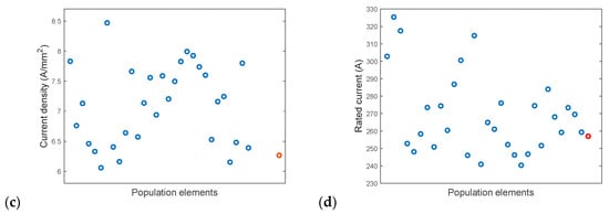
Figure 6.
Initial population distribution (blue circles), optimal solution (red circle): (a) Rotor external diameter (mm); (b) current density (A/mm2); (c) magnet height (mm); (d) rated current (A).
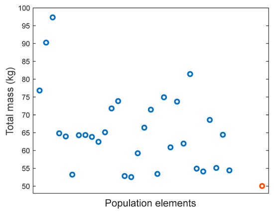
Figure 7.
Objective function values: Initial population distribution (blue circles), optimal solution (red circle).
Table 3.
Motor obtained with the optimization.
The Figure 8 and Figure 9 show the temperature distribution in a 2D section of the front end-windings, and the other one placed in the opposite site with respect to the propellers: it is evident that the maximum temperature (in K) are lower than the thermal class adopted and the maximum temperature in the resin.
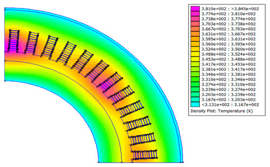
Figure 8.
Temperature inside a section of front-end windings of the optimum motor.
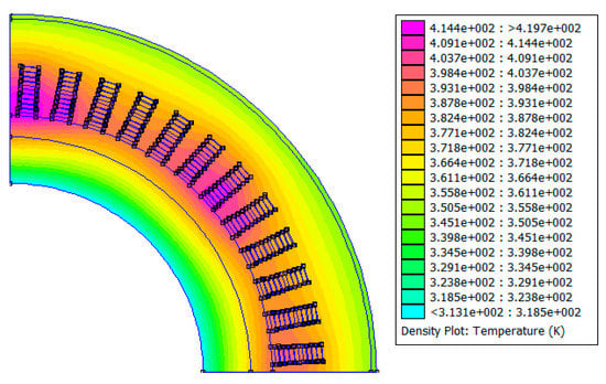
Figure 9.
Temperature inside a section of rear-end windings of the optimum motor.
(Problem 2) The number of the initial population is the same for Problem 1 and the iteration was stopped after about 350 iterations. The multi-objective problem is solved using the penalty function method, which consists of the transformation of one of the two objective functions into a constraint [38]. In our case the power density objective function is transformed into a constraint, imposing that:
In (41) the value 1.4 (kW/kg) indicates the minimum value for the power density. The iterations are stopped when the difference between the maximum and minimum value of rated power and of power density are both below 10% of the values in the initial population (besides, the threshold is 3 kW for the rated power and 0.05 kW/kg for the power density) and respect the constraint (41). The results are reported in Figure 10a–d and the positions of the element in the plane power density are shown in Figure 11. From Figure 11 is possible to note that, some elements in the initial population have a power density greater than 1.6 kW, but the rated power is limited to between 87–107 kW.
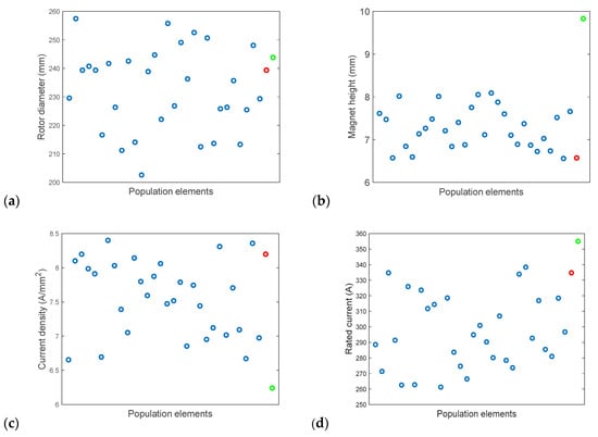
Figure 10.
Initial population distribution (blue circles), final solution with best power density (red circle) and with highest rated power (green circle): (a) Rotor external diameter (mm); (b) current density (A/mm2); (c) magnet height (mm); (d) rated current (A).
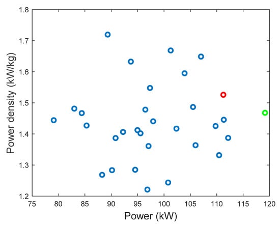
Figure 11.
Plane with both objective functions: Initial population distribution (blue circles), final solution with best power density (red circle), and with highest rated power (green circle).
For the final population, the position of the element with the best value of power (which also corresponds to the best value of the optimization problem) and the motor with the highest value of power density are depicted in the previous figures and are reported in Table 4 and Table 5:
Table 4.
Problem 2: best power density motor.
Table 5.
Problem 2: best rated power motor and best solution of the optimization problem.
Figure 12 and Figure 13 show the temperature in the front and rear end windings for both the solutions found. The temperature maps highlight that the motor with the best power density reaches a highest value of temperature with respect to the other one. The results can be easily explained and it is related to the fact that in the first motor the reduction of the overall mass determines a reduction of sizes and of heat transfer surface, with an increase of the temperature. In this case the maximum temperature is 209 °C and the value is near to the maximum temperature allowable for the resin.
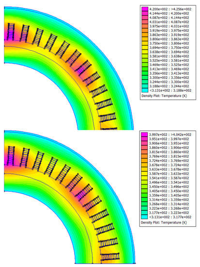
Figure 12.
Temperature in the front end-windings of the best power density motor (upper figure) and best rated power motor (lower figure).
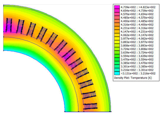
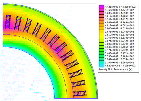
Figure 13.
Temperature in the rear end-windings of the best power density motor (upper figure) and best rated power motor (lower figure).
5. Conclusions
An optimized sizing procedure for an electric propulsion motor has been proposed in the paper. The goal of the procedure is to investigate the feasibility to use the external force convection of the air stream to cool the electric motors used in aircraft applications. Using the single impulsive theory for the propellers and modeling the external surface of the motor as a flat plate, the heat convective coefficient is calculated.
The optimization procedure is solved by using a differential evolution approach and the finite element analysis, both for the magnetic and thermal problems. The procedure is applied to two different problems: one for the design of a 60 kW motor, the other one to maximize the motor power density and the rated power. The obtained motor is characterized by an appreciable value of power density, considering also the severe constraints imposed on the maximum temperature and on the value of magnetic flux density.
Future works will exploit two different possibilities: one is inherent to the determination of overloadability power of the optimum motor, including this evaluation inside the sizing procedure. The latter is inherent to the development of a sizing procedure able to stress the temperature and magnetic flux density constraints to increase the power density of the motor.
Author Contributions
Conceptualization, L.P.D.N., and R.R.; methodology, L.P.D.N., L.P., and R.R.; software, L.P.D.N.; validation, L.P.D.N., L.P., and R.R.; investigation, L.P.D.N., and R.R.; writing—original draft preparation, L.P.D.N., and R.R; writing—review and editing, L.P., and R.R. All authors have read and agreed to the published version of the manuscript.
Funding
This research received no external funding.
Conflicts of Interest
The authors declare no conflict of interest.
Abbreviations
| A | (T·m) | Potential vector |
| ac | (m) | Slot opening |
| Ad | (m2) | Propeller area |
| bc | (m) | Wedge height |
| Bg | (T) | Maximum value of magnetic flux density in the air-gap |
| Br | (T) | Residual magnetic flux density of the permanent magnet |
| Bt | (T) | Maximum value of magnetic flux density in the tooth |
| By,s | (T) | Maximum value of magnetic flux density in the stator yoke |
| By,r | (T) | Maximum value of magnetic flux density in the rotor yoke |
| Dr,e | (m) | External diameter of the rotor |
| Dr,e,t | (m) | Initial value of external diameter of the rotor |
| Emot | (J) | Electromagnetic energy in the motor |
| fconv | (Hz) | Frequency of the converter |
| Fskin | Correction factor for eddy currents term in Iron losses calculation | |
| h | (W/(m2K)) | Heat exchange coefficient |
| hconst | Counter of the number of iterations without constraints respect | |
| hiter | Counter of the number of iterations without population substitution | |
| hm | (A) | Magnet length |
| hm,t | (A) | Initial value of magnet length |
| g | (m) | Air gap length |
| hc | (m) | Height of bar conductor |
| is,c | (m) | Conductor insulation thickness |
| is,k | (m) | Slot insulation film thickness |
| il | (m) | Insulation element between two layers |
| itlim | Number of iterations without constraints respect or not convergence | |
| In | (A) | Motor rated current |
| In,t | (A) | Initial value of motor rated current |
| J | (A/mm2) | Current density in the conductor |
| Jc | (A/m2) | Current density distribution in conductor due to the skin effect |
| Jt | (A/mm2) | Initial value of current density |
| k | (W/(mK)) | Air thermal conductivity |
| kcu | Slot fill factor | |
| ks | (°C/m) | Lapse rate |
| L | (m) | Plate length |
| lc | (m) | Length of the bar conductor |
| Ls | (H) | Synchronous inductance |
| (kg/s) | Mass flow | |
| Ns,p | Number of turns in series per pole and per phase | |
| Ncc | Number of conductors for slot | |
| Nu | Nusselt number | |
| p | Number of pole pairs | |
| pc | (m) | Height of slot opening |
| p00 | (Pa) | Pressure at point 1 of the tube flux |
| pff | (Pa) | Pressure at front face of the propeller |
| pbf | (Pa) | Pressure at back face of the propeller |
| P | (W) | Rated power of the motor |
| Pr | Prandtl number | |
| Q | Number of slots | |
| (W/m2) | Heat flux | |
| Re | Reynolds number | |
| Sc | (m2) | Conductor area |
| T | (N) | Trust force |
| T00 | (°C) | Air flux temperature |
| Tair | (°C) | Air temperature |
| Tend-wind | (°C) | End-windings temperature maximum value |
| Tmag | (°C) | Magnet temperature maximum value |
| Ts | (°C) | Surface temperature |
| Twind | (°C) | Windings temperature maximum value |
| V00 | (m/s) | Aircraft speed |
| vd | (m/s) | Disk tangential speed |
| vj | (m/s) | Induction speed |
| Vl | (V) | Voltage limit |
| ys | (m) | Stator yoke length |
| yr | (m) | Rotor yoke length |
| z | (m) | Altitude |
| µ | (H/m) | Magnetic permeability |
| ρ | (kg/m3) | Air mass density |
| ρcu | (kg/m3) | Copper mass density |
| (Wb) | Rotor flux | |
| σ | (S/m) | Electrical conductivity |
References
- Gohardani, A.S.; Doulgeris, G.; Singh, R. Challenges of future aircraft propulsion: A review of distributed propulsion technology and its potential application for the all-electric commercial aircraft. Prog. Aerosp. Sci. 2011, 47, 369–391. [Google Scholar] [CrossRef]
- Sarlioglu, B.; Morris, C.T. More Electric Aircraft: Review, Challenges, and Opportunities for Commercial Transport Aircraft. IEEE Trans. Transp. Electrif. 2015, 1, 54–64. [Google Scholar] [CrossRef]
- Gur, O.; Rosen, A. Optimizing electric propulsion systems for unmanned aerial vehicles. J. Aircraft. 2009, 46, 1340–1353. [Google Scholar] [CrossRef]
- Hung, J.Y.; Gonzalez, L.F. On Parallel Hybrid-Electric Propulsion System for Unmanned Aerial Vehicles. Prog Aerosp. Sci. 2012, 51, 1–17. [Google Scholar] [CrossRef]
- Misra, A. Summary of 2017 NASA Workshop on Assessment of Advanced Battery Technologies for Aerospace Applications. In Proceedings of the 2018 SciTech Forum, Kissimmee, FL, USA, 11 January 2018. [Google Scholar]
- Biradar, A.; DeBitetto, P.; Phan, L.; Duang, L.; Sarma, S. Hybrid-electric powered aerospace systems and the battery energy density revolution. In Proceedings of the 2018 IEEE Aerospace Conference, Big Sky, MT, USA, 3–10 March 2018; pp. 1403–1409. [Google Scholar]
- Rizzo, R.; Tricoli, P.; Spina, I. An Innovative Reconfigurable Integrated Converter Topology suitable for the Distributed Generation Energies. Energies 2012, 5, 3640–3654. [Google Scholar] [CrossRef]
- Di Noia, L.P.; Genduso, F.; Miceli, R.; Rizzo, R. Optimal integration of hybrid supercapacitor and IPT system for a free-catenary tramway. IEEE Trans. Ind. Appl. 2019, 55, 794–801. [Google Scholar] [CrossRef]
- Bocii, L.S.; Di Noia, L.P.; Rizzo, R. Optimization of the Energy Storage of Series-Hybrid Propelled Aircraft by Means of Integer Differential Evolution. Aerospace. 2019, 6, 59. [Google Scholar] [CrossRef]
- Del Pizzo, A.; Di Noia, L.P.; Rizzo, R. Energy storage system sizing for a twin engine four-seat aircraft electrical propulsion. Int. Rev. Aerosp. Eng. 2017, 10, 315–322. [Google Scholar] [CrossRef]
- Zhang, X.; Bowman, C.L.; O’Connell, T.C.; Haran, K.S. Large electric machines for aircraft electric propulsion. IET Electr. Power Appl. 2018, 12, 767–779. [Google Scholar] [CrossRef]
- Bodson, M.; Sadey, D.J.; Hunker, K.R.; Theman, C.J.; Taylor, L.M.; Csank, J.T. Hybrid electric propulsion using doubly-fed induction machines. AIAA J. Propuls. Power. 2020, 36, 78–87. [Google Scholar] [CrossRef]
- Smith, A.C.; Iacchetti, M.F.; Tuohy, P.M. Feasibility study of an induction motor rim drive for an aircraft boundary-layer-ingestion fan. J. Eng. 2019, 17, 4506–4510. [Google Scholar] [CrossRef]
- Golovanov, D.; Galea, M.; Gerada, C. High specific torque motor for propulsion system of aircraft. In Proceedings of the International Conference on Electrical Systems for Aircraft, Railway, Ship Propulsion and Road Vehicles & International Transportation Electrification Conference (ESARS-ITEC), Toulouse, France, 2–4 November 2016; pp. 1–6. [Google Scholar]
- Karashima, T.; Nakamura, T.; Okuno, M. Multidisciplinary analysis of the transient performance of a 20 kW class HTS induction/synchronous motor cooled with a cryocooler and gaseous air-gap coolant. Cryogenics 2019, 99, 61–67. [Google Scholar] [CrossRef]
- Terao, Y.; Kong, W.; Ohsaki, H.; Oyori, H.; Morioka, N. Electromagnetic Design of Superconducting Synchronous Motors for Electric Aircraft Propulsion. IEEE Trans. Appl. Supercond. 2018, 28, 1–5. [Google Scholar] [CrossRef]
- Zhang, G.; Hua, W.; Cheng, M.; Zhang, B.; Guo, X. Coupled Magnetic-Thermal Fields Analysis of Water Cooling Flux-Switching Permanent Magnet Motors by an Axially Segmented Model. IEEE Trans. Magn. 2017, 53, 1–4. [Google Scholar] [CrossRef]
- Yeo, H.; Park, H.; Seo, J.; Jung, S.; Ro, J.; Jung, H. Electromagnetic and Thermal Analysis of a Surface-Mounted Permanent-Magnet Motor with Overhang Structure. IEEE Trans. Magn. 2017, 53, 1–4. [Google Scholar] [CrossRef]
- Utegenova, S.; Dubas, F.; Jamot, M.; Glises, R.; Truffart, B.; Mariotto, D.; Lagonotte, P.; Désévaux, P. An Investigation into the Coupling of Magnetic and Thermal Analysis for a Wound-Rotor Synchronous Machine. IEEE Trans. Ind. Electron. 2018, 65, 3406–3416. [Google Scholar] [CrossRef]
- U.S Department of Defense, MIL-STD-810H (Environmental Engineering Considerations and Laboratory Tests), 523.4-4, USA. 2019. Available online: http://everyspec.com/MIL-STD/MIL-STD-0800-0899/download.php?spec=MIL-STD-810H.055998.pdf (accessed on 27 July 2020).
- Siemens SP200D Electric Motor. Available online: https://press.siemens.com/global/en/feature/electric-flight (accessed on 27 July 2020).
- Tognaccini, R. Rotor Aerodynamics. 2011. Available online: http://wpage.unina.it/rtogna/Aerodinamica_del_rotore.pdf (accessed on 28 July 2020). (In Italian).
- Nategh, S.; Boglietti, A.; Barber, D.; Liu, Y.; Brammer, R. Thermal and Manufacturing Aspects of Traction Motors Potting: A Deep Experimental Evaluation. IEEE Trans. Energy Convers. 2020, 35, 1026–1035. [Google Scholar] [CrossRef]
- Polikarpova, M.; Lindh, P.M.; Tapia, J.A.; Pyrhönen, J.J. Application of potting material for a 100 kW radial flux PMSM. In Proceedings of the 2014 International Conference on Electrical Machines (ICEM), Berlin, Germany, 2–5 September 2014; pp. 2146–2151. [Google Scholar]
- Kays, W.M.; Crawford, M.E. Convective Heat and Mass Transfer; Tata McGraw-Hill Education: Noida, India, 2012. [Google Scholar]
- White, F.M. Fluid Mechanics; McGraw-Hill: New York, NY, USA, 1979. [Google Scholar]
- Zarko, D.; Stipetic, S.; Martinovic, M.; Kovacic, M.; Jercic, T.; Hanic, Z. Reduction of Computational Efforts in Finite Element-Based Permanent Magnet Traction Motor Optimization. IEEE Trans. Ind. Electron. 2018, 65, 1799–1807. [Google Scholar] [CrossRef]
- Price, K.; Storn, R.M.; Lampinen, J.A. Differential Evolution: A Practical Approach to Global Optimization; Springer Science & Business Media: Berlin, Germany, 2006. [Google Scholar]
- Öksüztepe, E. In-Wheel Switched Reluctance Motor Design for Electric Vehicles by Using a Pareto-Based Multiobjective Differential Evolution Algorithm. IEEE Trans. Veh. Technol. 2017, 66, 4706–4715. [Google Scholar] [CrossRef]
- Sarigiannidis, A.G.; Beniakar, M.E.; Kladas, A.G. Fast Adaptive Evolutionary PM Traction Motor Optimization Based on Electric Vehicle Drive Cycle. IEEE Trans. Veh. Technol. 2017, 66, 5762–5774. [Google Scholar] [CrossRef]
- Silvester, P.P.; Ferrari, R.L. Finite Elements for Electrical Engineers, 3rd ed.; Cambridge University Press: Cambridge, UK, 1996. [Google Scholar]
- Salon, S.J. Finite Element Analysis of Electrical Machines; Kluwer Academic Publishers: Boston, MA, USA, 1995. [Google Scholar]
- Pyrhonen, J.; Jokinen, T.; Hrabovcova, V. Design of Rotating Electrical Machines; Wiley: Chichester, UK, 2007. [Google Scholar]
- Lipo, T.A. Introduction to AC Machine Design; Wiley: Madison, WI, USA, 1996. [Google Scholar]
- Slemon, G.R. On the design of high-performance surface-mounted PM motors. IEEE Trans. Ind. Appl. 1994, 30, 134–140. [Google Scholar] [CrossRef]
- Eggers, D.; Steentjes, S.; Hameyer, K. Advanced Iron-Loss Estimation for Nonlinear Material Behavior. IEEE Trans. Magn. 2012, 48, 3021–3024. [Google Scholar] [CrossRef]
- Zielinski, K.; Weitkemper, P.; Laur, R.; Kammeyer, K.-D.; Zielinski, K.; Laur, R. Examination of stopping criteria for differential evolution based on a power allocation problem. In Proceedings of the International Conference on Optimization of Electrical and Electronic Equipment (OPTIM), Brasov, Romania, 18–19 May 2006; pp. 149–156. [Google Scholar]
- Babu, B.V.; Jehan, M.M.L. Differential evolution for multi-objective optimization. In Proceedings of the 2003 Congress on Evolutionary Computation (CEC 2003), Canberra, Australia, 8–12 December 2003; pp. 2696–2703. [Google Scholar]


© 2020 by the authors. Licensee MDPI, Basel, Switzerland. This article is an open access article distributed under the terms and conditions of the Creative Commons Attribution (CC BY) license (http://creativecommons.org/licenses/by/4.0/).