Abstract
This paper presents the results of a study on the influence of pressure and temperature of the gas–water medium on the process of hydrocarbon gas hydrate formation occurring at the phase interface. Herein, a mathematical model is proposed to determine the optimum ratios of pressure, gas temperatures, water, and gas bubble sizes in the bubbling, gas ejection, or mixing processes. As a result of our work, we determined that gas hydrate in these processes is formed at the gas–water interface, that is, on the boundary surface of gas bubbles. Moreover, there is a gas temperature range where the hydrate formation rate reaches its maximum. These study findings can be used to optimize various technological processes associated with the production of gas hydrates in the industry.
1. Introduction
Recently, research into the properties of gas hydrates has intensified. There are a number of reasons for this. For one, natural gas hydrates, consisting mainly of methane hydrate, are considered as being promising sources of raw hydrocarbons. Indeed, the global estimate of hydrate-bound gas, best reflecting the current knowledge of underwater gas hydrate, is within the range of (1–5) × 1015 m3 (∼500–2500 Gt carbon methane) [1,2,3,4,5].
However, the lack of sufficient information on the features of their formation hinders the active implementation of gas hydrate technologies. Solving these problems will optimize the processes of extraction, synthesis, storage, transportation, and utilization of hydrates [6,7,8]. Currently, there are various ways of storing natural gas (methane), such as in liquefied form. In this state, gas can be transported from the source to the market, but as is, it is not convenient to store due to strict temperature requirements and problems with continuous gas boiling [9,10,11]. On the other hand, solid hydrates of natural gas are stable at moderately high pressures, (5 MPa) and 279 K [12].
Many researchers believe that the storage of natural gas in clathrate hydrates offers the safest, cleanest, and most compact storage approach. This opinion is explained by the relative convenience of post-storage natural gas recovery at a minimal cost compared to conventional storage methods [13,14,15,16]. The work [13] presents comprehensive information on the production, storage, and transportation of gas hydrates and proves the practicality of the transportation and storage of gases in a hydrated state.
Gas hydrate synthesis is one of the main stages of such technology. This process has the potential to be fast, continuous, relatively simple, and inexpensive. However, the stochastic character of hydrate nucleation and the slow kinetics of hydrate growth are the main challenges that need to be addressed in gas hydrate production. Still, deterministic and rapid nucleation combined with fast crystallization kinetics would enable the use of this technology for commercial applications.
In [17], the author performed an extensive analysis of hydrate synthesis methods. Accordingly, all the methods of gas hydrate synthesis involved the activation of mass transfer processes using chemical compounds, thermodynamic, mechanical activation, or a combination thereof [18,19,20,21,22,23,24,25]. Such initiation methods bring about an increase in the liquid volume, interface area, rector design optimization, and the intensification of gas diffusion conversion into the liquid, by using chemical reagents or thermodynamic parameters. One of the main reasons for the use of the initiation is to increase the hydrate formation rate to reach the maximum possible gas content in the hydrate structure. However, the hydrate synthesis rate decreases over time due to changes in the thermodynamic parameters in the hydrate formation reaction zone.
In our study, we consider the mechanical activation of gas hydrate synthesis, following a different concept—that the intensity of gas hydrate synthesis process is determined not only by the liquid volume or the size of the phase contact area, but also by the intensity of the phase interface renewal. Mechanical initiation, using bubble devices, is considered as the most promising technology [26,27,28] that follows this approach.
Gas mixing, spraying, and bubbling are known methods of gas hydrate synthesis intensification [29,30,31]. Nevertheless, in our opinion, these methods should also be evaluated in terms of the phase interface renewal rate. Hydrate films, formed on the bubbles surface, create resistance to heat removal during the exothermic hydrate formation reaction. On the other hand, these films at a certain stage of their formation can be easily deconstructed by the appropriate hydrodynamic and thermodynamic conditions inside the reactor, contributing to a constant intensive phase interface renewal and increase in the hydrate formation rate. The efficient heat removal from the reaction zone, however, requires further study.
These problems motivate us, and in this work, we propose the results of gas hydrate synthesis studies by the diffusion of gases through the phase interface boundary in the states of rest, mixing, and bubble phase interaction. This information is necessary to compare synthesis methods using diffusion and mechanical mixing activation (slow renewal of the phase interface surface), as well as in conditions of constant renewal. In the work, we plan to create corresponding hydrodynamic conditions under which gas bubbles will deform and change in size. These changes make it possible to keep the phase interface surface clean and, hence, to accelerate the gas hydrate synthesis process.
In this work, it is assumed that the gas hydrate synthesis rate will be constant or may even be increased by using a complex activation of the hydrate formation process. First, we considered the process in a stationary medium at the stationary phase interface surface with variable thermodynamic parameters to compare and evaluate our activation method.
2. Synthesis of Gas Hydrates
The formation of hydrates is accompanied by a significant release of heat, which causes the phase interface surface to heat up and the synthesis reaction to slow down. Moreover, the hydrate crust itself creates thermal resistance in the heat removal path, thus contributing to the slowing down rate of the hydrate methane synthesis. However, at the initial time (on a new phase interface surface), the hydrate formation intensity will be at its maximum. This point depends on a number of factors (Figure 1). However, even when creating the necessary thermodynamic conditions, the reaction of hydrate formation takes a long time [32,33,34,35]. Therefore, the purpose of the first series of experiments was to determine the optimal thermodynamic parameters of the reacting media to achieve the maximum possible hydrate methane synthesis rate and to study the hydrate crust effect at the interface on the intensity of heat and mass transfer processes.
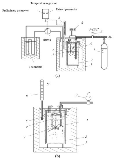
Figure 1.
Experimental plant with temperature stabilization of hydrate formation: (a)-diffusion hydration; (b)-replaceable module for the study of hydrate formation with the application of a high-speed mixer: 1-insulated housing; 2-capacity for high pressure; 3-manometer; 4-high pressure gas; 5-electronic temperature sensor: 6, 7-electrodes; 8-thermometer; 9-high-speed microelectric motor; 10-mixer impeller (gravity is not taken into account).
2.1. Experimental Studies of Diffusion Processes
The synthesis of gas hydrates synthesis is crucial to their production technology and storage, and this process intensity should be sufficiently high at near ambient temperatures and moderate pressures. A number of studies based on this should be noted, for example, [36], where the authors used bubbling or mixing [24,37] devices to intensify gas absorption process in the presence of surfactants. However, little attention was paid to investigating diffusion hydrate formation processes [12]. In our study, we investigated the process of diffusion hydrate formation and effect to emphasize the main factors affecting its intensity. To do this, water and one of the gases (methane, propane, or butane) were fed into reservoir 1. To maintain the temperature set in body 1, we used a thermostat with an AN CYRO-LTCCB circulator. The temperature was measured with a Pt100 thermometer. To measure gas pressure, a WIKA, A-10 sensor was used. Gas was then fed to experimental vessel 2. The temperature of vessel 2 was reduced by cool brine circulation, and the subcooling; P–T ratios were observed during the experiments at fixed time intervals. Hydrate formation was performed at constant pressure.
The study began with diffusion processes on a fixed interfacial surface.
In this experiment, methane, propane, or isobutane gases were fed through channel 7 to reactor 2. Here, gas temperature and pressure and water temperature were used as variable parameters. The obtained data for these gases are similar in terms of qualitative characteristics.
The results of the specific mass exchange approximation in the hydrate formation area for propane, kg/(m2 s), are:
For each experiment, the pressure and temperature were set and maintained at a constant using a thermostat and gas pressure regulator 4. In the experiment, the values of thermodynamic parameters corresponded to the hydrate formation area of studied gases at temperatures close to zero. Figure 2 shows the experimental values of the intensity of propane hydrate synthesis. The plant ensured stable gas temperature at a specified level by means of the external refrigerator. When undertaking the experiment, the reactor was first filled with the gas mixture at the temperature of 10 ÷ 15 °C. After temperature regulation, the initial pressure was measured. The temperature in the reactor was then reduced to the hydrate formation temperature and maintained for a specified time interval, and then time and gas pressure were monitored. The hydrate formation process occurs at the stationary phase interface. The experiment ended with an increase in the reactor temperature, hydrate dissociation, and gas volume measurement. Figure 2 shows the dependence for propane as an example. Here, if we divide Id value by the specific (initial) mass diffusion rate, we obtain a similar dependence of the synthesis rate change, which is characteristic of all the studied gases. The change in thermodynamic parameters does not affect the type of this dependence. However, the increase in supercooling of the liquid accelerates the synthesis process. The obtained results show that after reaching the temperature of hypothermia at 2.5 °C, the active hydrate formation of propane occurs, and the intense slowdown of mass transfer continues, despite the fact that there is hypothermia and sufficient excess pressure. Obviously, the crust of the formed hydrate dramatically slows down the process of subsequent hydrate formation.
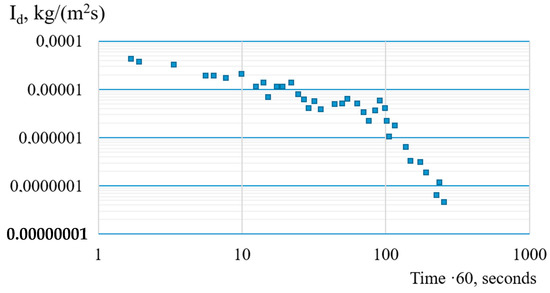
Figure 2.
Experimental data and approximation of specific mass transfer under hydrate formation conditions.
The freezing of the crust increases the thermal resistance of the phase interface, and, as a result, significantly reduces heat flow to the liquid. Figure 3 shows the dependence of crust thickness on temperature and pressure for the duration of the experiments shown in Figure 2.
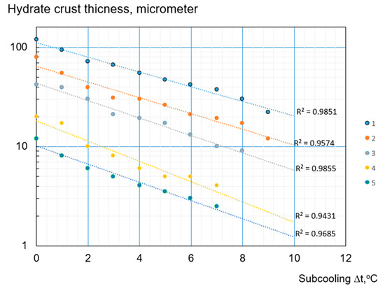
Figure 3.
Dependence of crust thickness on temperature and pressure: 1-P = 2.5 MPa; 2-P = 3 MPa; 3-P = 4 MPa; 4-P = 5 MPa; 5-P = 7.5 Mpa.
In [24,37,38,39,40], the effects of reactor volume, dimensions, and other geometric factors on the amount of entrapped gas were studied. We conducted similar studies, but we focused on determining the effect of the phase interface surface size and its renewal intensity on hydrate formation intensity. We discovered that the slow mixing of water, using the module shown in Figure 1b, slows down the process of hydrate crust formation, thus leading to a less considerable reduction in hydrate formation intensity. Moreover, the synthesis process rate will increase as the renewal of water-gas phase interface surface accelerates. Therefore, in our opinion, the actual renewal of the phase interface surface may be the main factor affecting the hydrate formation rate.
Thus, in thermobaric conditions of hydrate formation, we observed a sharp decrease in the intensity of mass transfer processes for a fixed interface surface. On the other hand, hydrate formation lines of exchange indicate the possibility of very intense mass transfer at initial times. Therefore, if the frozen hydrate crust is destroyed, a sufficiently high rate of hydrate formation can be maintained.
Now let us consider how the intensity of this process changes if hydrates form on gas bubble surfaces, when high-speed mixers are used and intense oscillations in gas size, pressure, and bubble temperatures destroy the hydrate crust.
2.2. Intensification of Mass Transfer Processes by Using a Mixer
Let us compare the results of the mass transfer under the conditions of simple diffusion and mixing using a mixer (Figure 1b), Figure 4.
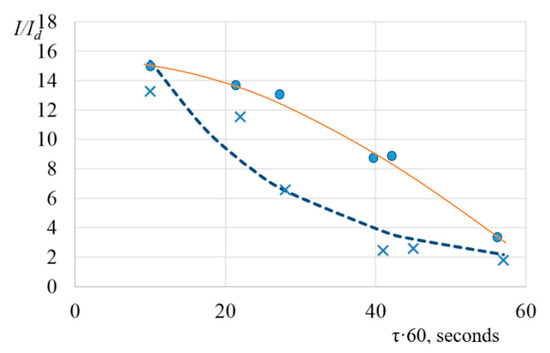
Figure 4.
Increases in the intensity of mass transfer between propane and water when a high-speed mixer is used, compared to free diffusion mode: ×-fixed interphase surface; - mixer rotation speed is 92 rpm.
The analysis of the experimental results shows that the use of the mixer leads to a significant acceleration of mass transfer processes (up to 40 times). However, the intensification of mass transfer in the hydrate formation area (6.4 times) is observed only after a long period of mixing.
The obtained data can be represented as an equation (R2 = 0.89):
where τ is the time in hours.
Thus, the mixer operation can enhance the activation of mass transfer at the start of the hydration process by approximately 7–8 times.
2.3. Use of Surfactants for the Intensification of Mass Transfer Processes on the Phase Interface Surface
In [24,37,40], the effect of surfactants on the hydration process acceleration was studied. Therefore, we will also analyze this effect in our experiments, based on our key point that the rate of interphase surface renewal has the greatest effect on the intensity of the hydrate synthesis process. The studies were performed in the module (Figure 1b). By changing the number of mixer revolutions, we observed fewer changes in the mass transfer intensity (Figure 4). This result is attributed to the constant renewal of the interpose surface. However, with time, the surface still forms a hydrate crust and the mass transfer processes slow down.
By using surfactants of various kinds, it is possible to significantly change the strength of the surface tension on the gas–water phase interface surface. Experimental studies show that the reduction of surface tension forces significantly affects the speed of gas hydrate formation and increases its gas capacity [12,41].
In our experiments, the best results on hydrate formation are observed with the use of a gel surfactant comprising a mixture of lauramine oxide 5% (non-ionic surfactant) with sodium laureth sulphate 10% (anionic surfactant). The specific feature of this mixture is the formation of stable foam, even in water with a temperature close to 0 °C. The obtained data show that the main reduction of surface tension occurs at a concentration of surfactants up to 0.1%. Further increases in concentration have little effect on the value of the surface tension coefficient. The minimum value obtained is σ = 0.021 N/m.
We noted that an increase in the number of mixer revolutions ensures the active mixing of the liquid and its capture of gas—in this case, dispersed in the form of bubbles. Thus, the phase interface surface increases where the hydrate crust also forms. However, this surface is not renewed. It is evident that the more bubbles that are formed, the more intense the mass transfer process will be. Herein, surfactants facilitate dispersion. During the operation of high-speed mixers, the maximum intensification of mass transfer in the application of surfactants was 2–2.5 times less than for distilled water. Still, it was determined that when using a surfactant, the duration of the high-speed mixer intensification period is 3 times that of distilled water. This means that the main mechanism of the activation of mass transfer, using surfactants, is to increase the duration of the existence of gas bubbles in water. The reduction of surface tension by adding surfactants to water contributes to the formation of a large number of small bubbles. In this case, the area of heat and mass exchange surfaces increases sharply. Thus, the studies performed show that even under suitable thermobaric conditions, with good mixing and the application of surfactants, it is not possible to quickly obtain a gas hydrate without an intensive removal of heat from the reaction area, which is prevented by hydrate crusting. When liquefied gas is supplied to chilled water, a high rate of gas hydrate formation is achieved. However, this method is not effective for methane since the maximum temperature of liquefied methane is −82.3 °C at 4.6 MPa.
The bubbling of gas in water and then in liquid gas makes it possible to obtain high-quality hydrate (Figure 5), but the hydrate formation efficiency decreases over time, as with the use of mixers or bubbling lines. The gas hydrate is formed at the phase interface in the form of a solid crust, which reduces the intensity of heat and mass transfer processes at the liquid–gas interface.
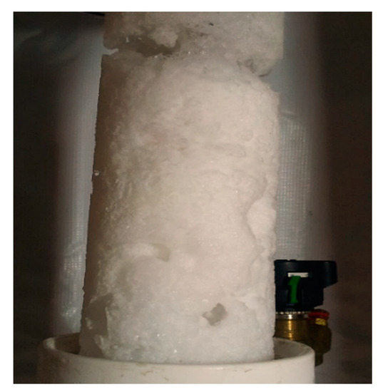
Figure 5.
Stabilized propane hydrate.
Thus, to maintain the intensity of gas hydrate formation, such hydrodynamic and thermodynamic conditions should be created, under which the solid hydrate formed on the phase interface surface (gas bubble) can convert into the liquid phase. Such an effect can be ensured by intense fluctuations in gas bubble size, pressure, and gas temperature. Another requirement is the intensive removal of heat from the hydrate layer into the liquid.
2.4. Formation of Gas Hydrate on Surfaces of Oscillating Gas Bubbles
Studies have shown that the diffusion nature of hydration can be considerably accelerated by the renewal of the gas–water interface, for example, on the surface of gas bubbles. Unfortunately, even if sufficient conditions for hydration are present, this process is slowed down as the hydration crust formed on the gas–water interface provides thermal resistance for heat dissipation. If the hydrate layer is permanently destroyed, however, a sufficiently high rate of the hydrate formation process will be observed. These conditions are formed by the gas being supplied to cooled water. If gas is distributed in bubbles with a pressure higher than its pressure in water and at a different temperature, these bubbles will undergo certain changes when entering the water: changes in size, pressure, and temperature with an oscillation of their values. The main effect of these processes is manifested in the deformation of the bubble shape and size, resulting in the destruction of the newly formed hydrate crust. Thus, the problem of thermal resistance increase in the hydrate structure can be solved by the removal of the exothermic reaction heat flow into the water layers that are closest to the bubble surface. Experimental studies were performed using the laboratory equipment shown in Figure 6.
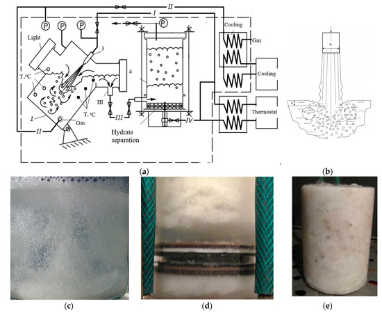
Figure 6.
Scheme of plant for gas hydrate production (a): 1-reactor; 2-gas; 3-jet apparatus; 4-separator: I, IV-water; II-gas; III-water and gas hydrate mixture: (b)-injection hydrate formation (phase interface surfaces); (c)-hydrate formation after hydrate crust destruction; (d)-separator; (e)-produced gas hydrate.
Since the hydrate crust is formed on gas bubble surfaces and can be easily deconstructed under certain thermodynamic conditions in the reactor and through the implementation of hydrodynamic dispersion of phases with the fastest possible renewal of the contact surface, jet apparatus 3 was used in the facility, shown in Figure 6. In reactor 1, gas bubbles are formed (Figure 6b) and are subjected to variable deformation. As a result, the hydrate crust formed on their surface is destroyed. Hydrodynamic and thermodynamic parameters in this work were determined experimentally and modelled using the mathematical equations shown in Section 4.
The synthesis process occurs within a temperature range of 273–288 K. The near ambient temperature is the maximum temperature in a reactor, the difference between the water–gas–hydrate mixture temperature at the reactor outlet and feed water temperature does not exceed 15 K.
The efficiency of heat removal during the synthesis reaction is an important parameter that defines the rate of exothermic processes. In gas hydrate production, as calculations show, about 80% of all input energy is spent on heat removal during the hydrate formation. Here, heat is removed outside the thermostat reaction zone through liquid circulation.
In the process of hydrate production, the gas pressure in reactor 1 is controlled by a WIKA, A-10 sensor, while the temperature is regulated by a Pt100 platinum thermocouple. Gas 2 is supplied in reactor 1 at the appropriate temperature and pressure. Water, supplied through nozzle 3, circulates inside the reactor. Hydrate crust, formed on gas bubbles, is deconstructed due to bubble size oscillations (Figure 6b). The produced loose hydrate is discharged with the circulating water (Figure 6c) into separator 4 (Figure 6a,d), where it is separated from water and gets compressed. Figure 7 shows the dependence of mass transfer intensity between propane and water compared to free diffusion mode.
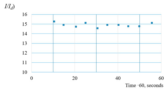
Figure 7.
Increase in mass transfer intensity between propane and water compared to free diffusion mode.
The data on the critical thermobaric conditions for hydrates of natural gases are summarized in Table 1.

Table 1.
Critical parameters of the hydrate formation of natural gases.
3. Heat Exchange and Gas Hydrate Formation in Liquids
3.1. Intensification of Heat Transfer between Bubble Surface and Liquid Masses
In our study, we demonstrated that the formation of a hydrate film at the phase interface is the main reason for the decrease in the gas hydrate synthesis rate. Figure 4 shows the study results of hydrate film formation providing thermal resistance to heat removal from the reaction zone, thus reducing the hydrate synthesis rate. In our reactor, we created hydrodynamic and thermodynamic conditions to deconstruct this film. Thus, there is no need to analyze the film thickness, or the period required for the formation of the rheological properties in which this film can be destructed. To address this problem, we propose the method of determining the thermodynamic parameters. For this, the film can be destructed through cyclic changes in gas bubble thermodynamic parameters and sizes. It should be noted that the gas bubbles change in size during the process of gas/water pressure and temperature equilibration. To evaluate the kinetics and the nature of these changes, let us analyze the equations describing the gas behavior during its transition to a new state of thermodynamic equilibrium. The inertial component of a bubble in a mathematical model can be written using the Rayleigh–Plasset equation [42,43]:
The fluid flow velocity () on the bubble boundary may be determined by the integration of Equation (3):
If the heat transfer processes occur on the bubble surface, its radius will change not only due to radial motion, but also due to the phase transition on the phase interfacial surface:
where Ip is the mass of fluid vapors, transferred through the surface unit of the bubble within the time unit, kg/(m2·s). As a rule, the offset of the phase transition impact is not high.
Let us assume that at the initial time moment a bubble with radius R0 and inside pressure PB0 appears in the fluid at pressure P∞. If the bubble is in the balance state with the fluid, using Equation (5) on condition we obtain:
If the initial pressure in the bubble is higher than PB0, it begins to grow. It if it less, it begins to compress. Let us determine the pressure inside the bubble at any time.
Due to the bubble size and temperature differences, as well as the diverse composition of gas–vapor mixture, the pressure inside the bubble changes within a wide range.
If the gas mass in a bubble changes as a result of mass exchange processes on its surface, then the gas density is determined by Equation (7) [42]:
To determine the temperature inside the gas bubble, the first law of thermodynamics is usually applied, from which we obtain:
Equation (8) contains several unknown values: specific heat flow (q), specific surface mass flow of gas (Ig), mass flow of steam (Ip), specific volumetric mass flows of gas (Igv), and steam (Ipv). The precondition of the heat flow emergence is temperature difference between the vapor bubble wall and the gas–vapor mixture inside the bubble. The difference in the partial pressures near the vapor bubble and its internal medium is a driving force for mass exchange flows.
The component T·(cgIg + cpIp) are heat flows supplied to the bubble wall due to mass transfer processes. At the same time, this heat flow is lost to the vapor–gas medium of the bubble. By marking it as qv = T·(cgIgv + cpIpv), Equation (8) is written as:
Equations (4), (5), and (9) describe the oscillations in gas bubble size. The resizing of the bubbles creates the conditions for the removal of the hydrate from the phase interface surface. Moreover, such oscillations induce turbulence within the flow of fluid around the surface of the bubbles and thus intensify the processes of heat and mass transfer.
3.2. Mass Exchange Processes in the Volume of the Gas Phase
To describe thermodynamic conditions, required for intensive heat removal from the reaction zone, we must solve the thermal problem to determine the efficient heat removal conditions. As the gas intensively changes its size, the gas temperature and pressure change in each bubble.
To determine the temperature in the liquid mass surrounding the gas bubble, it is necessary to consider the process of heat transfer in the liquid. To do this, we add known equations [42,43], modified to Equations (3)–(9) by the addition of several equations describing energy values.
To determine the unknown temperature of the bubble surface and of the liquid mass (T(x, τ)), a nonlinear equation of thermal conductivity can be used, considering the mobility of the bubble walls [43] and the action of volume heat sources:
As a result of the heat transfer processes at the bubble boundary, the liquid can change its thermophysical characteristics, so we will solve the problem as nonlinear. Moreover, the use of heat sources makes Equation (10) nonhomogeneous.
The effect of gas hydrate formation energy is considered by means of volume heat sources:
And the conditions of energy exchange at the phase boundary are represented by the following equation:
Equation (12) considers the change in the coefficient of thermal conductivity at the bubble boundary, for example, in case of liquid freezing. At a considerable distance from the bubble center, where the influence of other bubbles becomes the same, the boundary condition is described by:
While the initial time condition is:
Since the purpose of this mathematical model is to study the conditions of the hydrate formation of hydrocarbon gases, it is supplemented by equations describing the thermobaric conditions for hydrate existence.
Methane solubility in distilled water at a temperature of +4 °C is 0.0023 mole/kg. Propane and butane solubility are about 0.01% at a temperature of about 0 °C. Hydrate-forming gases such as hydrogen sulphide and carbon dioxide are much more soluble in water than hydrocarbons.
The hydrate forms, if , where -is equilibrium state of the hydrate at appropriate pressure, °C; critical temperature of the liquid above which the hydrate can no longer form (°C).
If the water temperature is below zero (ice formation), hydrate formation is dramatically slowed down, so for this case we will assume . Gas hydrate decomposition occurs-if i and , then . If there is no hydrate in water (mg = 0) and if , the mass transfer processes are absent and the hydrate is not formed or decomposed.
4. Research Results
To verify the calculated data, experimental studies were performed. It is known that thermobaric conditions determine the area of gas hydrate existence, so their impact is crucial. However, we are interested in quantitative indicators that affect gas hydrate formation speed. They are gas temperature and liquid temperature, as well as pressure in the liquid–gas system.
We will change the gas temperature from the beginning of the hydrate formation to the water freezing point on the methane bubble surface. The calculation results are shown in Figure 8 and Figure 9. The graphs show that the hydrate formation process begins almost immediately and reaches maximum values during bubble heating. The reduction of gas temperature to −10 °C (by 15.5 °C below hydrate formation temperature) increases hydrate formation amounts by 16.4 times. However, a further increase in the hydrate amount is slow enough and additional gas cooling is inefficient due to the freezing of inner layers and because the resistance to heat transfer between gas and the hydrate formation area increases sharply. Hence, the deterioration of heat dissipation slows down hydrate formation. However, the gas pressure increase contributes to the destruction of the hydrate crust on the surface of the gas bubbles, causing them to oscillate in size.
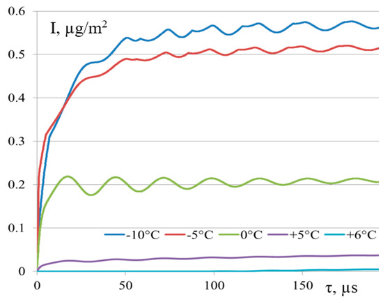
Figure 8.
Effect of initial gas temperature deviation from thermodynamic equilibrium conditions on hydration formation processes (equilibrium values are shown in Table 1).
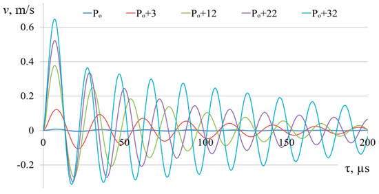
Figure 9.
Effect of gas pressure increase relative to the equilibrium level of the methane hydration processes (P, bar) (equilibrium values are shown in Table 1).
The results of the mathematical modelling show that the largest oscillations (damping vibrations) of the bubble are observed at the beginning of the hydrate formation process. The starting mechanism for these oscillations is the temperature difference between the gas–vapor medium of the bubble and the temperature of hydrate formation that is determined by the medium pressure. During hydrate formation, a local temperature rise of the liquid occurs, and then, due to heat exchange and the vapor–gas medium of the bubble, the rising gas temperature increases the pressure of the bubble and begins the process of increasing its diameter.
Still, the hydrate formation process will be much more intensive when the pressure exceeds the equilibrium for hydrate formation at a given temperature (P0). A number of mathematical experiments on the model were conducted to answer this question. The results of the mathematical modelling of hydrate formation at different methane pressures are shown in Figure 9.
By analyzing Figure 9, we can conclude that the amount of formed hydrate is proportional to the pressure in the gas–water system. To establish the effect of pressure on the motion of bubble walls, we refer to Figure 10.
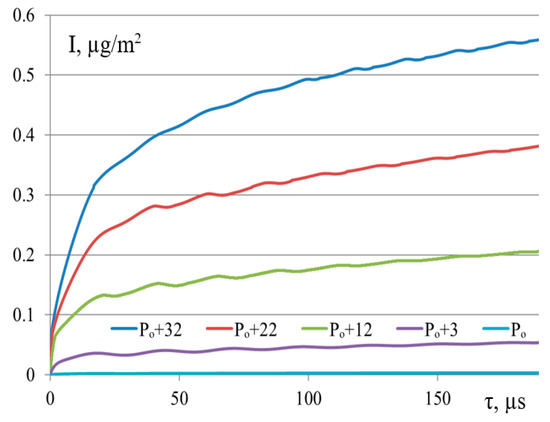
Figure 10.
The speed of wall motion of the methane bubble at different pressures, 105 Pa.
Figure 10 shows that with increasing pressure, the amplitude of the bubble velocity oscillations increases, and the oscillation frequency increases. The oscillation amplitude damping is slower as the amount of energy stored by the bubble increases.
The gas temperature in the bubble rises almost in proportion to the pressure increase. A comparison of Figure 9 and Figure 10 indicates that the basic hydrate formation process occurs in the first 20 μs and the achieved hydrate formation values can be maintained if the pressure under the hydrate formation crust conditions is reached at the boundary of phase interface. Therefore, a temperature decrease promotes hydrate formation, but only at the beginning of the process—as a solid hydrate crust is formed at the interface, which prevents removal of excess heat into the liquid. The increase in pressure leads to destruction of this crust by increasing the gas bubble oscillations, and the intensity of hydrate formation is preserved, as can be seen in Figure 9.
5. Study of Gas Hydrate Formation with Different Composition
Hydrate formation occurs as a result of mass transfer processes. Therefore, it is worth analyzing the effect of different gases on hydrate formation, both as separate (possibly in a mixture with water vapor) and binary gas mixtures. It is necessary to compare methane and propane to answer the question about the similarity of modelling processes of hydrate formation on propane and isobutane bubbles.
Let us compare the course of the hydration formation process for three gases: methane, propane, and isobutane. We take the diameter of all the bubbles to be equal to 1 mm. For methane, the water temperature is +5 °C and the gas temperature is 0.0 °C. The initial propane temperature in the bubble is 4.0 °C and the water temperature is +1 °C. For the isobutane bubble, the water temperature is +0.5 °C, and the gas temperature is 4.5 °C.
Calculation results of the pressure inside each bubble are shown in Figure 11. The comparison shows 10 times the amplitude of the oscillation of the methane bubble, and 4 times the frequency of oscillations compared to propane and isobutene alone. In such a situation, there is an intense damping of methane bubble oscillations, as the methane pressure is 15 times higher than the propane pressure and the propane pressure is 1.5 times higher than the isobutane pressure.
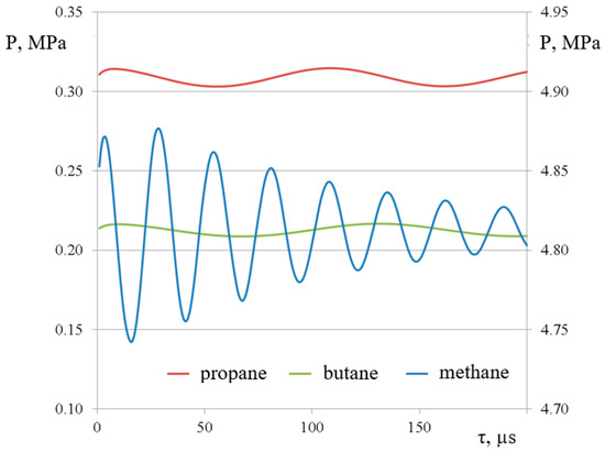
Figure 11.
Inside bubble gas pressure (methane-right axle, propane and isobutane-left).
For the methane bubbles, the oscillation frequency is f = 45 kHz, for propane, it is f = 9.1 kHz, and for isobutene, it is f = 7.7 kHz.
Figure 12 shows the intensity of the hydrate formation process for bubbles with different gases. The methane hydrate formation speed is approximately 10 times that of the propane and isobutane hydrate formation speed. Here, with increasing pressure, the intensity of the hydrate formation increases.
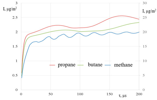
Figure 12.
Hydrate specific amount (methane-right axle, propane and isobutane-left).
The proposed mathematical model makes it possible to establish an effective pressure–temperature ratio for the hydrate formation process. With such thermodynamic parameters, the amplitude and frequency of bubble size change and thermodynamic parameters inside the gas bubble can be achieved; the hydrate film will be deconstructed to ensure a stable hydrate synthesis rate over time. The hydrate samples shown in the photos were obtained as follows (Figure 6). They can remain stable for a long time and allow an investigation of the conditions of the storage or transportation of gas hydrates over certain distances. The results of such studies will be presented in follow-up articles.
6. Conclusions
Hydrate formation processes diffuse slowly but can be significantly accelerated by using a diffusion-convective mechanism of heat and mass transfer. The initial temperature of the vapor–gas medium of the bubble significantly affects the hydrate formation process. The most intense hydrate formation occurs at the site of the initial heating of the vapor–gas medium of the bubble. During hydrate formation, a local temperature rise in the liquid occurs, and then continues due to heat exchange and the vapor–gas medium of the bubble. The maximum speed of hydrate formation is observed during gas heating in the bubble. This period has a short duration of 2–40 μs, but it is the most productive.
After the heat-up period, there are oscillations (damped oscillations) in bubble size. The starting mechanism for these oscillations is the temperature difference between the gas–vapor medium of the bubble and the temperature of the hydrate formation, which, in turn, is determined by the medium pressure. The rising gas temperature increases the bubble pressure and begins the process of enhancing its diameter. During the oscillations, hydrate formation also occurs, but at some points in time, its decomposition can be observed. This is especially noticeable at very low gas temperatures (+3–0 °C).
Due to friction in the viscous liquid, the oscillations gradually slow down and the hydration process is supported by heat transfer to the outer layers of the liquid. Since this process is limited by the considerable heat transfer resistance of both the liquid and the formed hydrate layers, the hydrate formation speed decreases. It is possible to preserve the process intensity by combining the pressure–temperature ratios. With increasing pressure, the hydrate crust is destroyed at the interface, thus creating resistance to heat transfer. The proposed mathematical model enables us to determine this ratio, as well as establish the optimal values of gas bubble size, and gas and liquid temperatures.
The increase in pressure has a positive effect on the hydrate formation process, but it is limited by the condensation area of propane–butane mixture components. Thus, technologically, to accelerate hydration, it is necessary to lower the gas temperature in the bubble and increase the pressure to create long-term oscillations of the bubbles for the rapid destruction of the gas hydrate crust. The optimum pressure and temperature values depend on the gas composition, fluid temperature, and the size of the bubbles.
Funding
This research was funded by grant number 025/RID/2018/19 “Regional Initiative of Excellence” in 2019–2022.
Conflicts of Interest
The author declares no conflict of interest.
Abbreviations
| P | pressure, Pa; |
| T, t | temperature, K, °C; |
| Id | diffusion mass transfer, kg/(m2 s); |
| τ | time, s; |
| I | mass transfer, kg/(m2 s); |
| R | gas bubble radius, m; |
| µ | coefficient of liquid dynamic viscosity, Pa s; |
| σ | coefficient of liquid surface tension, N/m; |
| ρ | liquid density, kg/m3; |
| PB(τ) | pressure inside the bubble, Pa; |
| P∞(τ) | pressure in the liquid at a distance from the bubble, Pa. |
| Igv, Ipv | mass flow of gas and steam, kg/(m3 s); |
| q | specific heat flow, J; |
| Ig | mass flow of gas, kg/(m2 s); |
| Ip | mass flow of steam, kg/(m2 s); |
| ρr | liquid density, kg/m3; |
| cr | heat capacity, J/(kg °C); |
| rate of change of bubble radius, m/s; | |
| λr | the effective coefficient of thermal conductivity of the liquid, W/(m °C); |
| qv | capacity of volumetric heat sources, W/m3; |
| ri | specific heat of the ith phase transition, J/kg; |
| mi | mass of the substance involved in the phase transition, kg; |
| ∂V | elementary volume, m3. |
References
- Alexei, V. Milkov Global estimates of hydrate-bound gas in marine sediments: How much is really out there? Earth-Sci. Rev. 2004, 66, 183–197. [Google Scholar]
- Boswell, R.; Collett, T.S. Collett Current perspectives on gas hydrate resources. Energy Environ. Sci. 2011, 4, 1045–1528. [Google Scholar] [CrossRef]
- Zhao, J.; Zhu, Z.; Song, Y.; Liu, W.; Zhang, Y.; Wang, D. Analysing the process of gas production for natural gas hydrate using depressurization. Appl. Energy 2015, 142, 125–134. [Google Scholar] [CrossRef]
- Brown, T.D.; Taylor, C.E.; Bernardo, M.P. Rapid Gas Hydrate Formation Processes: Will They Work? Energies 2010, 3, 1154–1175. [Google Scholar] [CrossRef]
- Chong, Z.R.; Yang, S.H.; Babu, P.; Linga, P.; Li, X.S. Review of natural gas hydrates as an energy resource: Prospects and challenges. Appl. Energy 2016, 162, 1633–1652. [Google Scholar] [CrossRef]
- Kipyoung, K.; Youtaek, K.; Hokeun, K. Recent advances in natural gas hydrate carriers for gas transportation. JKOSME 2014, 38, 589–601. [Google Scholar] [CrossRef]
- Ke, W.; Svartaas, T.M.; Chen, D. A review of gas hydrate nucleation theories and growth models. J. Nat. Gas Sci. Eng. 2019, 61, 169–196. [Google Scholar] [CrossRef]
- Archer, D. Methane hydrate stability and anthropogenic climate change. Biogeosciences 2007, 4, 521–544. [Google Scholar] [CrossRef]
- Vysniauskas, A.; Bishnoi, P.R. A kinetic study of methane hydrate formation. Chem. Eng. Sci. 1983, 38, 1061–1072. [Google Scholar] [CrossRef]
- Abay, H.K.; Svartaas, T.M. Effect of Ultralow Concentration of Methanol on Methane Hydrate Formation. Energy Fuels 2010, 24, 752–757. [Google Scholar] [CrossRef]
- Bahadori, A. Chapter 13—Liquefied Natural Gas (LNG). In Natural Gas Processing; Bahadori, A., Ed.; Gulf Professional Publishing: Boston, MA, USA, 2014; pp. 591–632. [Google Scholar]
- Kiran, B.S.; Sowjanya, K.; Prasad, P.S.; Yoon, J.H. Experimental investigations on tetrahydrofuran-methane-water system: Rapid methane gas storage in hydrates. Oil Gas Sci. Technol.-Rev. IFP Energ. Nouv. 2019, 74, 12. [Google Scholar] [CrossRef]
- Veluswamy, H.P.; Kumar, A.; Seo, Y.; Lee, J.D.; Linga, P. A review of solidified natural gas (SNG) technology for gas storage via clathrate hydrates. Appl. Energy 2018, 216, 262–285. [Google Scholar] [CrossRef]
- Kim, K.; Kang, H.; Kim, Y. Risk Assessment for Natural Gas Hydrate Carriers: A Hazard Identification (HAZID) study. Energies 2015, 8, 3124–3164. [Google Scholar] [CrossRef]
- Veluswamy, H.P.; Kumar, A.; Kumar, R.; Linga, P. An innovative approach to enhance methane hydrate formation kinetics with leucine for energy storage application. Appl. Energy 2017, 188, 190–199. [Google Scholar] [CrossRef]
- Zhao, J.; Zhao, Y.; Liang, W. Hydrate-based gas separation for methane recovery from coal mine gas using tetrahydrofuran. Energy Technol. 2016, 4, 864–869. [Google Scholar] [CrossRef]
- Veluswamy, H.P. Energy Storage in Clathrate Hydrates. Ph.D. Thesis, National University of Singapore, Singapore, 2015; 267p. [Google Scholar]
- Arora, A.; Cameotra, S.S.; Kumar, R.; Balomajumder, C.; Singh, A.K.; Santhakumari, B.; Kumar, P.; Laik, S. Biosurfactant as a promoter of methane hydrate formation: Thermodynamic and kinetic studies. Sci. Rep. 2016, 6, 20893. [Google Scholar] [CrossRef] [PubMed]
- Kumar, A.; Bhattacharjee, G.; Kulkarni, B.D.; Kumar, R. Role of surfactants in promoting gas hydrate formation. Ind. Eng. Chem. Res. 2015, 54, 12217–12232. [Google Scholar] [CrossRef]
- Veluswamy, H.P.; Hong, Q.W.; Linga, P. Morphology study of methane hydrate formation and dissociation in the presence of amino acid. Cryst. Growth Des. 2016, 16, 5932–5945. [Google Scholar] [CrossRef]
- Liu, Y.; Chen, B.; Chen, Y.; Zhang, S.; Guo, W.; Cai, Y.; Tan, B.; Wang, W. Methane storage in a hydrated form as promoted by leucines for possible application to natural gas transportation and storage. Energy Technol. 2015, 3, 815–819. [Google Scholar] [CrossRef]
- Veluswamy, H.P.; Lee, P.Y.; Premasinghe, K.; Linga, P. Effect of biofriendly amino acids on the kinetics of methane hydrate formation and dissociation. Ind. Eng. Chem. Res. 2017, 56, 6145–6154. [Google Scholar] [CrossRef]
- Mohammad-Taheri, M.; Moghaddam, A.Z.; Nazari, K.; Zanjani, N.G. Methane hydrate stability in the presence of water-soluble hydroxyalkyl cellulose. J. Nat. Gas Chem. 2012, 21, 119–125. [Google Scholar] [CrossRef]
- Sharma, D.; Sowjanya, Y.; Chari, V.D.; Prasad, P.S.R. Methane storage in mixed hydrates with tetrahydrofuran. Indian J. Chem. Technol. 2014, 21, 114–119. [Google Scholar]
- Sowjanya, Y.; Prasad, P.S.R. Formation kinetics & phase stability of double hydrates of C4H8O and CO2/CH4: A comparison with pure systems. J. Nat. Gas Sci. Eng. 2014, 18, 58–63. [Google Scholar]
- Lucia, B.; Castellani, B.; Rossi, F.; Cotana, F.; Morini, E.; Nicolini, A.; Filipponi, M. Experimental investigations on scaled-up methane hydrate production with surfactant promotion: Energy considerations. J. Pet. Sci. Eng. 2014, 120, 187–193. [Google Scholar] [CrossRef]
- Rossi, F.; Filipponi, M.; Castellani, B. Investigation on a novel reactor for gas hydrate production. Appl. Energy 2012, 99, 167–172. [Google Scholar] [CrossRef]
- Luo, Y.T.; Zhu, J.H.; Fan, S.S.; Chen, G.J. Study on the kinetics of hydrate formation in a bubble column. Chem. Eng. Sci. 2007, 62, 1000–1009. [Google Scholar] [CrossRef]
- Cheng, C.; Wang, F.; Tian, Y.; Wu, X.; Zheng, J.; Zhang, J.; Li, L.; Yang, P.; Zhao, J. Review and prospects of hydrate cold storage technology. Renew. Sustain. Energy Rev. 2020, 117, 109492. [Google Scholar] [CrossRef]
- Lang, X.; Fan, S.; Wang, Y. Intensification of methane and hydrogen storage in clathrate hydrate and future prospect. J. Nat. Gas Chem. 2010, 19, 203–209. [Google Scholar] [CrossRef]
- Murakami, T.; Kuritsuka, H.; Fujii, H.; Mori, Y.H. Forming a Structure-H Hydrate Using Water and Methylcyclohexane Jets Impinging on Each Other in a Methane Atmosphere. Energy Fuels 2009, 23, 1619–1625. [Google Scholar] [CrossRef]
- Smirnov, G.S.; Stegailov, V.V. Melting and superheating of sI methane hydrate: Molecular dynamics study. J. Chem. Phys. 2012, 136, 044523. [Google Scholar] [CrossRef]
- Zhao, J.; Cheng, C.; Song, Y.; Liu, W.; Liu, Y.; Xue, K.; Zhu, Z.; Yang, Z.; Wang, D.; Yang, M. Heat Transfer Analysis of Methane Hydrate Sediment Dissociation in a Closed Reactor by a Thermal Method. Energies 2012, 5, 1292–1308. [Google Scholar] [CrossRef]
- Gulbrandsen, A.C.; Svartås, T.M. Effects of PVCap on gas hydrate decomposition kinetics and the thermodynamic stability of the hydrates. Energy Fuels 2017, 31, 9863–9873. [Google Scholar] [CrossRef]
- Veluswamy, H.P.; Wong, A.J.; Babu, P.; Kumar, R.; Kulprathipanja, S.; Rangsunvigit, P.; Linga, P. Rapid methane hydrate formation to develop a cost effective large scale energy storage system. Chem. Eng. J. 2016, 290, 161–173. [Google Scholar] [CrossRef]
- Veluswamy, H.P.; Kumar, S.; Kumar, R.; Rangsunvigit, P.; Linga, P. Enhanced clathrate hydrate formation kinetics at near ambient temperatures and moderate pressures: Application to natural gas storage. Fuel 2016, 182, 907–919. [Google Scholar] [CrossRef]
- Delahaye, A.; Fournaison, L.; Marinhas, S.; Chatti, I.; Petitet, J.P.; Dalmazzone, D.; Fürst, W. Effect of THF on equilibrium pressure and dissociation enthalpy of CO2 hydrates applied to secondary refrigeration. Ind. Eng. Chem. Res. 2006, 45, 391–397. [Google Scholar] [CrossRef]
- Mech, D.; Gupta, P.; Sangwai, J.S. Kinetics of methane hydrate formation in an aqueous solution of thermodynamic promoters (THF and TBAB) with and without kinetic promoter (SDS). J. Nat. Gas Sci. Eng. 2016, 35, 1519–1534. [Google Scholar] [CrossRef]
- Fan, S.; Yang, L.; Wang, Y.; Lang, X.; Wen, Y.; Lou, X. Rapid and high capacity methane storage in clathrate hydrates using surfactant dry solution. Chem. Eng. Sci. 2014, 106, 53–59. [Google Scholar] [CrossRef]
- Ricaurte, M.; Torre, J.P.; Diaz, J.; Dicharry, C. In situ injection of THF to trigger gas hydrate crystallization: Application to the evaluation of a kinetic hydrate promoter. Chem. Eng. Res. Des. 2014, 92, 1674–1680. [Google Scholar] [CrossRef]
- Pavlenko, A.M. Dispersed phase breakup in boiling of emulsion. Heat Transf. Res. 2018, 49, 633–641. [Google Scholar] [CrossRef]
- Pavlenko, A. Energy conversion in heat and mass transfer processes in boiling emulsions. Therm. Sci. Eng. Prog. 2020, 15, 100439. [Google Scholar] [CrossRef]
- Pavlenko, A.M. Change of emulsion structure during heating and boiling. Int. J. Energy A Clean Environ. 2019, 20, 291–302. [Google Scholar] [CrossRef]


© 2020 by the author. Licensee MDPI, Basel, Switzerland. This article is an open access article distributed under the terms and conditions of the Creative Commons Attribution (CC BY) license (http://creativecommons.org/licenses/by/4.0/).