Abstract
Carbon nanotubes (CNTs) and polyelectrolyte poly(allylamine hydrochloride) (PAH) composite modified indium tin oxide (ITO) electrodes, by a layer-by-layer (LBL) self-assembly technique, was evaluated as an anode for microbial fuel cells (MFCs). The bioelectrochemistry of Shewanella loihica PV-4 in an electrochemical cell and the electricity generation performance of MFCs with multilayer (CNTs/PAH)n-deposited ITO electrodes as an anode were investigated. Experimental results showed that the current density generated on the multilayer modified electrode increased initially and then decreased as the deposition of the number of layers (n = 12) increased. Chronoamperometric results showed that the highest peak current density of 34.85 ± 2.80 mA/m2 was generated on the multilayer (CNTs/PAH)9-deposited ITO electrode, of which the redox peak current of cyclic voltammetry was also significantly enhanced. Electrochemical impedance spectroscopy analyses showed a well-formed nanostructure porous film on the surface of the multilayer modified electrode. Compared with the plain ITO electrode, the multilayered (CNTs/PAH)9 anodic modification improved the power density of the dual-compartment MFC by 29%, due to the appropriate proportion of CNTs and PAH, as well as the porous nanostructure on the electrodes.
1. Introduction
Microbial fuel cells (MFCs) are a type of bioreactor, which directly harvests electricity from chemical energy by exoelectrogens (i.e., microorganisms transferring electrons to an electrode). Recently, they have been widely used in power generation, wastewater treatment and biosensors [1,2,3,4,5,6,7]. In particular, the electron transfer occurs between: Redox-active outer membrane c-type cytochromes (OM c-Cyts) of the microbe, or redox-active mediators secreted by the cells/added outside, or microbially generated nanowires and the electrode surface [8]. Amongst several factors—such as the electrodes [9], microorganisms, operation conditions and structure of the MFCs [10]—anodes directly in contact with exoelectrogens have a significant impact on bioelectrochemical properties and electricity generation performance of MFCs. Therefore, the development of anodes with high-performance, which facilitate the electron transfer, cell attachment and substrate oxidation, are critical for the improvement of MFC performance and cost-effectiveness [11].
Recently, the application of various electrodes such as carbon cloth, carbon paper, carbon felt, graphite and reticulated vitrified carbon in MFCs has attracted the attention of many researchers [12,13,14,15,16,17]. Carbon materials with high surface area exhibited a high influence on the performance of MFCs. Aside from usage of carbon materials, modification of electrodes with nanostructured materials not only increased surface area and electrocatalytic properties of the anode, but also enabled the anode to obtain functional groups, facilitating electron transfer, microbial respiration and proliferation [18]. Carbon nanotubes (CNTs) with the advantage of forming porous structures easily have been widely utilized as filters for electrochemical degradation of organic pollutants [19], catalytic membranes in continuous flow reactors [20], and biocatalytic anodes in MFCs, due to their high surface-to-volume ratios, high conductivity, superior electrochemical characteristics, excellent mechanical and chemical stability, and ease of modification [21,22]. Qiao et al. constructed CNTs and a polyaniline composite film coated nickel foam anode in MFCs, where the 20 wt.% CNTs deposited composite anode exhibited a maximum power density of 42 mW/m2 with Escherichia coli as the electricigen [23]. In another study, Sun et al. used multi-wall carbon nanotube (MWCNT) and polyelectrolyte polyethyleneimine (PEI) modified carbon paper anode by the layer-by-layer (LBL) self-assembly technique. Here, the MFC with the modified electrode generated a high power density with ~20% improvement comparing to the bare carbon paper with mixed-culture anaerobic granular sludge as the biocatalyst [24]. Similarly, Roh has shown that MWCNT/PEI-modified carbon paper anodes generated the maximum power density of 480 mW/m2, which was 48% higher than the value of plain carbon paper electrodes, with Shewanella putrefaciens as the electricigen [25]. Zhang et al. coated LBL CNTs on graphite electrodes by electrophoretic deposition. Here, the CNTs-modified electrodes facilitated electron transfer [26]. Miniaturized MFC results also showed that the spin-spray LBL CNTs anode had a low sheet resistance, thick biofilm generation and high power density [21]. The fabrication of the CNTs modified anode has resulted in enhanced electrocatalytic properties of MFCs.
The LBL self-assembly technique is a versatile approach to prepare the controllable multilayer films by non-covalent intermolecular interactions among charged or hydrogen-bonding moieties [27]. Previously reported studies focused on the electrochemical behaviors of LBL-assembled CNTs/PEI composite modified Toray carbon paper electrodes and CNTs-modified graphite electrodes in potassium ferricyanide solution without electricigens. However, the effects of the controllable amount of CNTs and nanostructure of the CNTs-modified films on both bioelectrochemical performance of electricigens and electricity generation of the MFCs were not investigated. Furthermore, it was reported that CNTs have antimicrobial activity and cellular toxicity [28,29]. However, the effect of the CNT toxicity on the electrochemical activity and cell vitality of the electricigens in MFCs has not received much attention. Indium tin oxide (ITO) has a potential high-impact due to its high electrical conductivity, optical transparency, and promising application in electrochemical devices. It has been widely utilized as a substrate for the adsorption of biomolecules, and a working electrode to explore the electron transfer between exoelectrogens and the electrode surface in the bioelectrochemical system [30,31]. In this paper, CNTs multilayer modified ITO electrodes with controllable quantities of CNTs and surface nanostructures were fabricated using a LBL self-assembly technique, by alternately depositing the positively charged poly(allylamine hydrochloride) (PAH) and negatively charged CNTs through electrostatic interactions. The electrochemical catalytic activity of the multilayered film (CNTs/PAH)n-deposited ITO electrode in the bioelectrochemical system and its electricity generation performance in MFCs with Shewanella loihica PV-4 as the electricigen were elucidated. The effect of CNT toxicity on the electrochemical activity and cell proliferation of S. loihica PV-4, as well as the cell attachments on the electrode in the MFCs were also studied.
2. Materials and Methods
2.1. Materials
Indium tin oxide (ITO) conductive glasses were purchased from Hong Kong physical and chemical Co. Ltd. Poly(allylamine hydrochloride) (PAH) was purchased from Sigma-Aldrich Co. Ltd. (Shanghai, China). MWCNTs (99.8%, 400 nm diameters) were purchased from Times Nano Co. Ltd. (Chengdu, China), which were purified and oxidized before use. The proton exchange membrane Nafion 117 (Dupont) was obtained from Beijing Honghaitian Science and Technology Co. Ltd. (Beijing, China). Other chemicals, including lactate sodium, potassium ferricyanide, sulfuric acid, hydrogen peroxide, nitric acid, sodium chloride ammonium chloride, sodium bicarbonate, were purchased from Sinopharm Chemical Reagent Co. Ltd. (Beijing, China). All the reagents were analytically pure grade and not purified further for use. Deionized water was used in all the experiments.
2.2. Preparation and Characterization of Multilayer Film (CNTs/PAH)n-Deposited ITO Anode
The processes of construction of the multilayered film (CNTs/PAH)n-deposited ITO electrode by LBL self-assembly are shown in Scheme 1. Firstly, the CNTs were modified with carboxylic acid groups in a mixture of H2SO4-HNO3 (volume ratio 3:1) for 24 h, then filtered and cleaned with ultrapure water. The ITO electrode was modified with hydroxyl groups in a mixture of 98% H2SO4 and 30% H2O2 solution (volume ratio 7:3) for 10 min. Secondly, the bilayer (CNTs/PAH) with CNTs at the outer layer of the ITO electrode was fabricated by immersion of the electrode into PAH aqueous solution (1 mg/mL) for 30 min, transferred into CNTs aqueous solution (1 mg/mL) for 30 min, washed with deionized water for 5 min and dried in hot air. By repeating these procedures 3, 5, 7, 9 and 12 times, different layers of CNTs/PAH bilayer composite films were obtained on the ITO electrode and characterized with an ultraviolet-visible near-infrared (UV–vis-NIR) spectrometer (UV 2600, Shimadzu, Japan). Water contact angles were characterized using a data-physics OCA20 contact angle system (Data-Physics, CA, USA). Two different samples were measured for each sample, three different spots were measured and the data were averaged.
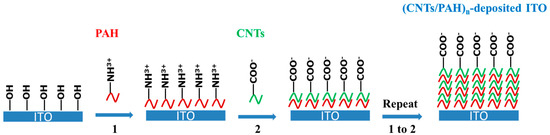
Scheme 1.
Schematic presentation of fabrication of multilayered film carbon nanotubes (CNTs)/ polyelectrolyte poly(allylamine hydrochloride) (PAH)n-deposited indium tin oxide (ITO) electrode by layer-by-layer (LBL) self-assembly.
2.3. Bacteria Culture
The Shewanella loihica PV-4 strain (ATCC BAA-1088) was aerobically cultured in 10 mL of Marine Broth (20 g/L) at 30 °C for 24 h, then the Marine Broth was centrifuged and replaced with 10 mL of defined media (NaHCO3 2.5 g/L; CaCl2·2H2O 0.08 g/L; NH4Cl 1.0 g/L; MgCl2·6H2O 0.2 g/L; NaCl 10 g/L; 2-[4-(2-Hydroxyethyl)-1-piperazinyl]ethanesulfonic acid 7.2 g/L) [32] with lactate sodium (10 mM) as the sole carbon source, at 30 °C for 48 h, pH 7.8. The suspension was centrifuged for 10 min and washed with defined media three times before the electrochemical experiments.
2.4. Electrochemical Tests
A three-electrode, single-chamber system was utilized for the electrochemical tests, where the multilayered film (CNTs/PAH)n-deposited ITO electrode or bare ITO electrode was utilized as the working electrode by placing at the bottom of the reactor [32], a platinum wire as the counter, and an Ag/AgCl (saturated KCl) electrode were the reference. The reactor was filled with 4 mL of defined media with 10 mM lactate sodium and deaerated by purging N2 gas for 30 min. The bacterial culture (OD600 2.0) was subsequently injected into the reactor at a constant poised potential of 0.2 V and recorded on a CHI 660D potentiostat (CH Instruments, Chenhua Co. Shanghai, China) at 25 °C. All these experiments were performed in triplicate.
Cyclic voltammetry (CV) was carried out in the reactor before inoculation, after 25 h of chronoamperometry, at a scan rate of 100 mVs−1 and range of −1.0 to 1.0 V, to examine the catalytic capability of the electrode. The electrochemical impedance spectroscopy (EIS) was also performed at open circuit potential, in the frequency range from 100 KHz to 0.1 Hz and with an amplitude of 10 mV.
2.5. Scanning Electron Microscopy (SEM)
S. loihica PV-4 on the surface of electrodes were observed by SEM (S-4800 and SU8010 UHR FE-SEM, HITACHI, Tokyo, Japan). Samples were fixed in 2.5% (v/v) glutaraldehyde in 0.2 M phosphate buffer (pH 7.0) for 2 h and washed with 50 mM phosphate buffer (pH 7.0) for three times. After this, they were dehydrated by a 60%, 70%, 80%, 90% and 100% alcoholic series, and then freeze-dried for SEM observations.
2.6. Polarization Curve Test
A two-chambered MFC of 14 mL in each cubic cell was set up. A Nafion proton exchange membrane with an area of 7 cm2 was sandwiched between the two chambers. The bare ITO electrode or CNTs-modified ITO electrode was utilized as the MFC anode. The MFC cathode was a square piece of 7 cm2 plain carbon cloth (Phychemi (Hongkong) Co. Ltd., Beijing, China). The cathodic compartment was fed with 10 mM ferricyanide in 100 mM phosphate buffer saline (PBS) solution (pH 7.4). The anodic compartment was fed with defined media, with 10 mM lactate sodium. The anode chamber was inoculated with bacterial culture (OD600 2.0) after purging N2 gas for 30 min. The constructed MFC was placed in a temperature-controlled incubator (DHG-907CA, Shanghai Jing Hong Laboratory Instrument Co. Ltd., Shanghai, China) at 30 °C. The open circuit voltage was recorded with a multi-channel data acquisition board (NI USB-6008, Beijing Huatai Orient Technology Co., Ltd. Beijing, China). The polarization and power density curves were tested by changing the load resistance from 50 to 10,000 Ω at the plateau of MFC output voltage.
3. Results and Discussion
3.1. Surface Characterization of CNTs/PAH Electrodes
The assembly process of the LBL multilayer films on the ITO electrode was characterized by UV-vis-NIR absorption spectroscopy. As shown in Figure 1, optical absorbance of the composite film arises from the absorption of the CNTs, due to the transparent PAH over the measured wavelength range [24,33,34]. As the bilayer number of the composite films increased, the absorbance at 430 nm—arising from the CNTs—increased. This indicated that CNTs with carboxylic acid groups were well-assembled with PAH to form composite films and that the number of CNTs corresponding with the electrode thickness increased with the increase of bilayer number, during the assembly process of the (CNTs/PAH)n-deposited ITO electrode [33]. The content of the C element on the (CNTs/PAH)n-deposited ITO electrode, as analyzed by the energy dispersive spectroscopy (EDS), also increased with the bilayer number of composite film (Table 1). These results demonstrated that CNTs/PAH was successfully deposited on the ITO electrode by the LBL method and the thickness of composite film increased with bilayer number.
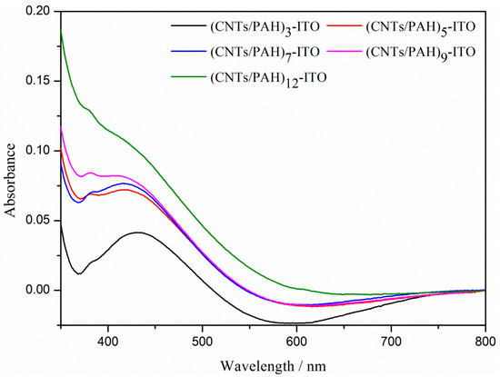
Figure 1.
Ultraviolet-visible near-infrared (UV–vis-NIR) spectroscopy of the (CNTs/PAH)n-deposited ITO electrode (n = 3, 5, 7, 9, 12).

Table 1.
The content of C element on the (CNTs/PAH)n-deposited ITO electrode analyzed by energy dispersive spectroscopy (n = 0, 3, 5, 7, 9, 12).
The static water contact angles (θc) of the multilayer film (CNTs/PAH)n-deposited ITO electrodes were tested to evaluate their hydrophilicity. As shown in Figure 2, the θc of the bare ITO electrode was 72.84 ± 4.64°and with the increase of bilayer number from 3 to 12, the θc of the multilayer film (CNTs/PAH)n-deposited ITO electrode gradually decreased from 65.82 ± 1.83° to 40.14 ± 2.20°. This indicated the hydrophilicity improvement of the anode surfaces.
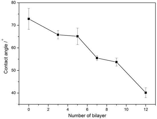
Figure 2.
The static water contact angles (θc) of the multilayer film (CNTs/PAH)n-deposited ITO electrodes.
3.2. Chronoamperometric Results
Figure 3 depicts the current density generated on the bare ITO electrode and multilayered film (CNTs/PAH)n-deposited ITO electrode, at a potential of 0.2 V by S. loihica PV-4. With the injection of S. loihica PV-4 cells (OD600 2.0) into the bioelectrochemical reactor, a current was generated instantaneously, which then increased to a plateau value on the multilayered film (CNTs/PAH)n-deposited ITO electrode at a bilayered number of 0, 3, 5 and 7. Both the oxidation peak current and plateau current increased with the multilayer number. However, after increasing the number of layers to 9, the oxidation current kept on increasing with the injection of cells and reached the highest current density of 34.85 ± 2.80 mA/m2, and then slightly decreased. The peak current density generated on the (CNTs/PAH)9-deposited ITO electrode was 14 times higher than that on the bare ITO electrode of 2.34 ± 0.38 mA/m2. However, the current decreased with a peak current of 26.17 ± 3.04 mA/m2 at the multilayered film (CNTs/PAH)12-deposited ITO electrode. When the number of bilayers increased from 0 to 9, the increased current generated on the multilayer modified ITO electrode was ascribed to the increased amount of CNTs with high surface-to-volume ratios, high conductivity, and high electrocatalytic activity [26,35], which increased the availability of redox-active sites and accelerated the electron transfer between the electrode and cells. When the modified multilayer number increased from 9 to 12, an obvious decrease in current was observed on the (CNTs/PAH)12-deposited ITO electrode. One reason was the accumulation of negatively charged carboxyl groups of CNTs on the outer surface of the multilayer modified ITO electrode, which could repulse bacteria with negative charge surfaces attached on the electrode surface. Another reason was the antimicrobial activity and cellular toxicity of CNTs, which may have led to the death of cells and resulted in the low current generation on the (CNTs/PAH)12-deposited ITO electrode. Our previous results showed that the addition of sodium lactate per 25 h thrice did not increase the current due to the toxicity of CNTs on bacteria [36]. The additional chronoamperometric results of the 8, 10 and 11 bilayer modified ITO electrodes showed that the peak current density generated on the electrode firstly increased with the increase of bilayer number from 7 to 9, and then decreased with the increase of the bilayer number from 9 to 12. These results proved that the (CNTs/PAH)9 multilayer modified ITO electrode with appropriate amounts of CNTs had the most optimistic bioelectrochemical performance. These results were similar to reported results that the current density generated by S. loihica PV-4 was improved on the (Au/PAH)4/BDD electrode [37], (Fe2O3/CS)4/ITO electrode [38] and ITO/(PAH/GE)2 electrode [35] due to the appropriate amount of Au nanoparticles, Fe2O3 nanorods, graphene and thickness of PAH and chitosan. However, with respect to the current densities generated on other electrode materials—such as the (CNTs/PANI)12/APTES/ITO electrode (70.3 mA/m2) [36], graphite electrode (585 mA/m2) and CNT-coated graphite electrode (1429 mA/m2) [26]—that of the (CNTs/PAH)9-ITO electrode was unsatisfied, probably due to the increase of electron’s pathway distance between microbe and electrode, caused by the insulated PAH.
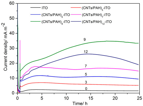
Figure 3.
Evolution of current density with time generated by S. loihica PV-4 on the (CNTs/PAH)n-deposited ITO electrode (n = 0, 3, 5, 7, 9, 12) poised at 0.2 V.
3.3. Electrochemical Characteristics of the Modified Electrode
The multilayered film (CNTs/PAH)n-deposited ITO electrodes were firstly characterized by cyclic voltammetry (CV) in defined media solution with 10 mM lactate sodium (pH 7.8). As shown in Figure 4a, a pair of well-defined reversible redox waves were observed at a formal potential of −50 mV, which was ascribed to the redox reaction that produced oxygen-containing groups [34]. The redox peak current evidently increased with the increase of the bilayer number from 3 to 9, reflecting the growth of the CNTs on the electrode. However, the (CNTs/PAH)12 multilayer modified ITO electrode exhibited decreased anodic and cathodic peak currents as the number of bilayers increased from 9 to 12. This may be ascribed to a slower mass transfer in thicker multilayer films of CNTs/PAH [26].
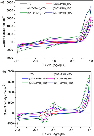
Figure 4.
Cyclic voltammetry (CV) of the (CNTs/PAH)n-deposited ITO electrode (n = 0, 3, 5, 7, 9, 12) before (a) and after (b) 25 h of chronoamperometry at a scan rate of 100 mV/s.
After being poised at 0.2 V for 25 h, the voltammogram of the multilayered film (CNTs/PAH)n-deposited ITO electrodes showed well-defined redox peaks with a mid-point potential (Em) of −0.22 V, which should be responses of OM c-Cyts. It has been reported that OM c-Cyts are in a broad potential range from −0.13 V to −0.27 V [26,39,40,41]. This result was in accordance with the results of a nanograss array boron-doped diamond electrode [32] and a gold nanoparticles-modified boron-doped diamond electrode [37] with S. loihica PV-4 as the electricigen. As the number of multilayers deposited on the ITO electrode increased from 0 to 9, both the anodic and cathodic peak currents increased, except the anodic peak current generated on the (CNTs/PAH)7 multilayer modified electrode, which was slightly lower than that generated on the multilayered film (CNTs/PAH)5-deposited electrode. In addition, an apparent decrease of redox current peak was observed at similar circumstances provided. This indicated that multilayer (CNTs/PAH)9-deposited ITO electrode had superior electrocatalytic properties. These results were in accordance with the chronoamperometric results.
3.4. Electrochemical Impedance Spectroscopy
The electrode interfacial resistance of bare and multilayered film-deposited ITO electrodes was measured by electrochemical impedance spectroscopy (EIS). As shown in Figure 5, the ITO electrode had no defined semicircle. The impedance plots of 3, 5, 7 and 12 bilayer modified ITO electrodes were dominated by a capacitive-like line and the deviation of phase angle from -90 degrees at low frequencies, which indicated porous conducting films [42]. Furthermore, the short straight line at low frequencies of the impedance plots of 3, 5, 7 and 12 bilayer modified ITO electrodes suggested the diffusion control in the doping/de-doping process [23]. These narrow regions of the diffusion control process indicated fast reactant diffusion without limitation over a wide frequency range, due to the well-formed nanostructure porous film on the surface of electrode [43]. However, the Nyquist plots of the (CNTs/PAH)9-deposited electrode displayed a semicircle in a high frequency range and a straight line in a low-frequency range, which indicated the combination of charge transfer and mass transfer processes on the electrode [44]. This unique property could ascribe to the well-formed nanostructure and accumulation of highly conductive CNTs on 9 layers of the CNTs/PAH modified electrode. In addition, the intercept of the real part (Z′) representing the ohmic resistance (Rs) increased with the layer number. The Rs of the bare ITO electrode and 3, 5, 7, 9 bilayer modified ITO electrodes were 29.93, 38.15, 41.81, 48.1 and 51.41 Ω respectively. The Rs of the (CNTs/PAH)12-deposited electrode (51.03 Ω) was nearly the same as that of the (CNTs/PAH)9-deposited electrode. This suggested that the modification of layers increased the connection resistance between the ITO substrate and the deposited multilayer [43,44].
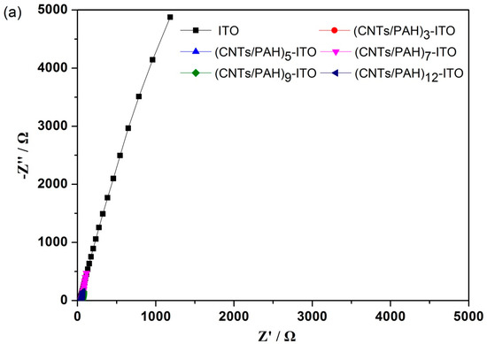
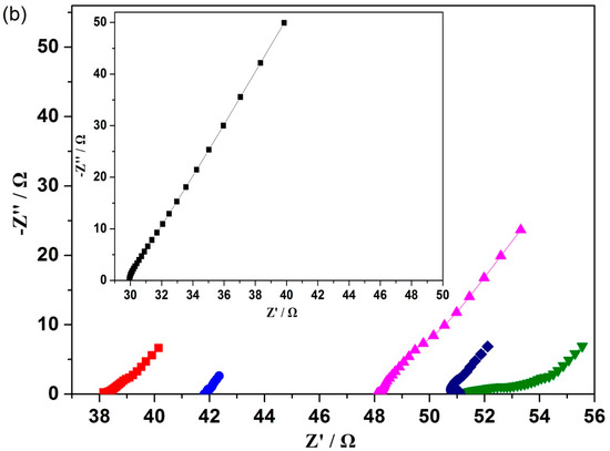
Figure 5.
Nyquist plots of the (CNTs/PAH)n-deposited ITO electrode (n = 0, 3, 5, 7, 9, 12) after 25 h of chronoamperometry (a) and their higher magnifications of the high frequencies parts (b). The inset in panel (b) shows the magnified plot of the bare ITO electrode.
3.5. Scanning Electron Microscopy
The morphology of the multilayer (CNTs/PAH)n-deposited ITO electrode after the chronoamperometric test was observed by SEM (Figure 6). Compared to the bare ITO electrode, the multilayer-deposited electrode exhibited high surface roughness and obvious pore structure, indicating that the CNTs/PAH multilayer was successfully deposited on the electrode surface. With the increase in multilayer number, the amount of CNTs increased corresponding with a higher surface area, while the layer deposited on the electrode surface became more compact together with the decrease of porosity on the porous structure after seven layers. Cell attachment on the electrode firstly increased with the multilayer number until five layers, and then decreased at layer 7 and 9. A significant decrease in cell attachment with low cell activity was observed on the surface of the 12 layer modified electrode. We acknowledged that CNTs are cytotoxic and this could inhibit cell proliferation or cause cell death [28,29]. The decrease in cell attachment on the modified electrode could be ascribed to the increasing amount of toxic CNTs and the decreasing porous nanostructure favorable for substrate transfer [43]. It was reported that microbes highly connected to the electrode by OM c-Cyts were unfavorable for microbial respiration, due to protection against oxidative stress [41,45]. Therefore, the electrochemistry behavior of S. loihica PV-4 was greatly enhanced on the (CNTs/PAH)9 multilayer modified ITO electrode without prominent cell adhesion. The significant accumulation of toxic CNTs and insulated PAH on the 12 layer modified electrode together with its poor porous nanostructure resulted in the poor electrochemical performance of the electrode. These results were in accordance with the chronoamperometric and voltammetric results. This indicated that the appropriate proportion of CNTs and insulated polyelectrolyte, as well as porous nanostructure, played an important role in the electrochemical and electricity generation performance of MFCs [35,37].
Figure 6.
SEM images of (CNTs/PAH)n-deposited ITO electrode after 25 h of chronoamperometry. (a–e: n = 3, 5, 7, 9, 12).
3.6. Polarization Curve
Based on the above results, the MFC with the multilayered film (CNTs/PAH)9-deposited ITO anode was chosen for the polarization curve test. The polarization curves were performed after the dual-compartment MFC reached a steady state. As shown in Figure 7, the cell voltage of the MFC with the (CNTs/PAH)9 multilayer modified ITO anode was higher than that of the bare ITO anode, suggesting that the (CNTs/PAH)9 multilayer deposition increased the output voltage of the MFCs. The polarization curve firstly increased to a maximum power density and then decreased. The power generation in the MFC with the (CNTs/PAH)9 multilayer modified ITO anode was higher than that of the MFC with the bare ITO electrode. The bare ITO electrode delivered a maximum power density of 4.6 ± 0.5 mW/m2 (at a cell voltage of 151 ± 13 mV), while the (CNTs/PAH)9 multilayer modified ITO anode displayed a maximum power density of 5.98 ± 0.3 mW/m2 (at a cell voltage of 133 ± 28 mV), which improved the power output of the MFC by 29% compared with the plain ITO anode. The maximum power density was obtained when the external resistor was equal to the internal resistance of the MFC. As shown in Figure 7, the internal resistance of the MFC with the (CNTs/PAH)9 multilayer modified ITO anode (~3000 Ω) was much lower than that of the MFC with the plain ITO anode (~5000 Ω). The lower internal resistance of the (CNTs/PAH)9 multilayer modified anode system accelerated the electron transfer between the bacteria and the anode, which resulted in higher power density [43]. This indicated that CNTs had been successfully modified on the surface of the ITO electrode by the LBL assembly method and had played an important role in improving the electricity generation performance of the MFCs, due to its high surface area and electrical conductivity [22,46,47]. However, as compared to the maximum power densities of other anodes also with high surface area in Table 2, an unsatisfactory power density was also harvested on the (CNTs/PAH)9 ITO anode. The reason for this could be that the increasing number of bilayers increased the electron’s pathway distance between the cells and electrode with the increasing amount of insulated PAH. Furthermore, although SEM and contact angles results showed that CNTs/PAH modified electrodes had a porous nanostructure with a high specific surface, and their wettability was increased, this porosity in the nanoscale was not accessible by microbes in the microscale and hence was not useful for power generation.
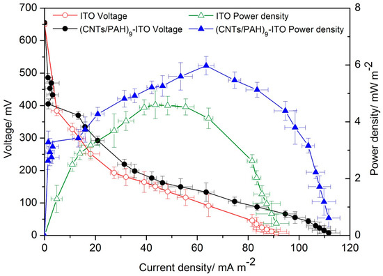
Figure 7.
Polarization and power density curves of the MFCs with the (CNTs/PAH)9-deposited ITO anode and the bare ITO anode.
Table 2.
Composition of the maximum power densities of anodes in the MFCs.
4. Conclusions
In summary, CNTs/PAH multilayer deposition on an ITO anode by the LBL self-assembly technique was successfully prepared in the present study. The amount of CNTs and porous nanostructures on the electrode were precisely controlled by the increase in the CNTs/PAH multilayer number. The oxidation peak current generated on the multilayer modified electrode increased with the increase of the CNTs/PAH multilayer number and then decreased at a layer number of 12. Chronoamperometric results showed that the highest peak current density of 34.85 ± 2.80 mA/m2 was generated on the (CNTs/PAH)9 multilayer modified ITO electrode, of which the redox peak current in the CV results was also greatly enhanced. EIS results showed that the electron transfer efficiency increased with the increase of multilayer number, corresponding with the increase of mass transfer resistance. SEM results showed that the appropriate proportion of CNTs and PAH, as well as the porous nanostructure, were vital for bacterial attachment on the electrode and the bioelectrochemical properties of the MFCs. The electricity generation performance of dual-compartment MFCs with the (CNTs/PAH)9 multilayer modified ITO anode was improved by 29%, as compared with the MFCs with the plain ITO anode. The LBL assembly technique could be a promising modification method for controlled incorporation of CNTs and porous nanostructures on electrodes. Further optimization of the modification method with conductive materials and an increase of electrode porosity accessible for microbes should improve the MFC performance. In addition, cheaper base materials instead of ITO should be utilized for scaling up of the MFCs in practical application.
Author Contributions
Conceptualization, W.W.; methodology, H.N.; validation, J.W., J.L. and C.H.; writing—original draft preparation, W.W.; writing—review and editing, D.Y.; supervision, S.-B.W.
Funding
This paper was supported by the Promotion Program for Young and Middle-Aged Teachers in Science and Technology Research of Huaqiao University (ZQN-PY315), the Outstanding Young Scientific Research Personnel Training Plan in Colleges and Universities of Fujian Province in 2015, the Natural Science Foundation of Fujian Province of China (No. 2016J01402) and Quanzhou Science and Technology Plan Project (2018C017).
Conflicts of Interest
The authors declare no conflict of interest.
References
- Wu, W.; Lesnik, K.L.; Xu, S.; Wang, L.; Liu, H. Impact of tobramycin on the performance of microbial fuel cell. Microb. Cell Fact. 2014, 13, 91. [Google Scholar] [CrossRef]
- Abourached, C.; English, M.J.; Liu, H. Wastewater treatment by Microbial fuel cell (MFC) prior irrigation water reuse. J. Clean. Prod. 2016, 137, 144–149. [Google Scholar] [CrossRef]
- Liu, H.; Ramnarayanan, R.; Logan, B.E. Production of electricity during wastewater treatment using a single chamber microbial fuel cell. Environ. Sci. Technol. 2004, 38, 2281–2285. [Google Scholar] [CrossRef]
- Wu, W.; Gu, Z.; Liu, X.; Bai, L.; Tang, Z. Nanograss array boron-doped diamond electrode for toxicity sensor with Shewanella loihica PV-4 in bioelectrochemical systems. Sens. Lett. 2014, 12, 191–196. [Google Scholar] [CrossRef]
- Wang, L.; Liu, Y.; Ma, J.; Zhao, F. Rapid degradation of sulphamethoxazole and the further transformation of 3-amino-5-methylisoxazole in a microbial fuel cell. Water Res. 2016, 88, 322–328. [Google Scholar] [CrossRef] [PubMed]
- Cecconet, D.; Callegari, A.; Capodaglio, A.G. Bioelectrochemical systems for removal of selected metals and perchlorate from groundwater: A review. Energies 2018, 11, 2643. [Google Scholar] [CrossRef]
- Wlodarczyk, P.P.; Wlodarczyk, B. Microbial fuel cell with Ni-Co cathode powered with yeast wastewater. Energies 2018, 11, 3194. [Google Scholar] [CrossRef]
- Xie, X.; Hu, L.B.; Pasta, M.; Wells, G.F.; Kong, D.S.; Criddle, C.S.; Cui, Y. Three-dimensional carbon nanotube-textile anode for high-performance microbial fuel cells. Nano Lett. 2011, 11, 291–296. [Google Scholar] [CrossRef] [PubMed]
- Sanchez, D.V.P.; Jacobs, D.; Gregory, K.; Huang, J.Y.; Hu, Y.S.; Vidic, R.; Yun, M. Changes in carbon electrode morphology affect microbial fuel cell performance with Shewanella oneidensis MR-1. Energies 2015, 8, 1817–1829. [Google Scholar] [CrossRef]
- Borjas, Z.; Ortiz, J.M.; Aldaz, A.; Feliu, J.; Esteve-Nunez, A. Strategies for reducing the start-up operation of microbial electrochemical treatments of urban wastewater. Energies 2015, 8, 14064–14077. [Google Scholar] [CrossRef]
- Cui, H.F.; Du, L.; Guo, P.B.; Zhu, B.; Luong, J.H.T. Controlled modification of carbon nanotubes and polyaniline on macroporous graphite felt for high-performance microbial fuel cell anode. J. Power Sources 2015, 283, 46–53. [Google Scholar] [CrossRef]
- Asensio, Y.; Montes, I.B.; Fernandez-Marchante, C.M.; Lobato, J.; Canizares, P.; Rodrigo, M.A. Selection of cheap electrodes for two-compartment microbial fuel cells. J. Electroanal. Chem. 2017, 785, 235–240. [Google Scholar] [CrossRef]
- Penteado, E.D.; Fernandez-Marchante, C.M.; Zaiat, M.; Gonzalez, E.R.; Rodrigo, M.A. Influence of carbon electrode material on energy recovery from winery wastewater using a dual-chamber microbial fuel cell. Environ. Technol. 2017, 38, 1333–1341. [Google Scholar] [CrossRef]
- Xia, K.; Bhandari, A.; Das, K.; Pillar, G. Occurrence and fate of pharmaceuticals and personal care products (PPCPs) in biosolids. J. Environ. Qual. 2005, 34, 91–104. [Google Scholar] [CrossRef] [PubMed]
- Westerhoff, P.; Yoon, Y.; Snyder, S.; Wert, E. Fate of endocrine-disruptor, pharmaceutical, and personal care product chemicals during simulated drinking water treatment processes. Environ. Sci. Technol. 2005, 39, 6649–6663. [Google Scholar] [CrossRef] [PubMed]
- Christwardana, M.; Frattini, D.; Accardo, G.; Yoon, S.P.; Kwon, Y. Early-stage performance evaluation of flowing microbial fuel cells using chemically treated carbon felt and yeast biocatalyst. Appl. Energy 2018, 222, 369–382. [Google Scholar] [CrossRef]
- Frattini, D.; Accardo, G.; Ferone, C.; Cioffi, R. Fabrication and characterization of graphite-cement composites for microbial fuel cells applications. Mater. Res. Bull. 2017, 88, 188–199. [Google Scholar] [CrossRef]
- Zhao, C.E.; Gai, P.P.; Song, R.B.; Chen, Y.; Zhang, J.R.; Zhu, J.J. Nanostructured material-based biofuel cells: Recent advances and future prospects. Chem. Soc. Rev. 2017, 46, 1545–1564. [Google Scholar] [CrossRef]
- Liu, Y.; Xie, J.; Ong, C.N.; Vecitis, C.D.; Zhou, Z. Electrochemical wastewater treatment with carbon nanotube filters coupled with in situ generated H2O2. Environ. Sci.-Water Res. Technol. 2015, 1, 769–778. [Google Scholar] [CrossRef]
- Liu, Y.; Zheng, Y.; Du, B.; Nasaruddin, R.R.; Chen, T.; Xie, J. Golden carbon nanotube membrane for continuous flow catalysis. Ind. Eng. Chem. Res. 2017, 56, 2999–3007. [Google Scholar] [CrossRef]
- Ren, H.; Pyo, S.; Lee, J.I.; Park, T.J.; Gittleson, F.S.; Leung, F.C.C.; Kim, J.; Taylor, A.D.; Lee, H.S.; Chae, J. A high power density miniaturized microbial fuel cell having carbon nanotube anodes. J. Power Sources 2015, 273, 823–830. [Google Scholar] [CrossRef]
- Yazdi, A.A.; D’Angelo, L.; Omer, N.; Windiasti, G.; Lu, X.N.; Xu, J. Carbon nanotube modification of microbial fuel cell electrodes. Biosens. Bioelectron. 2016, 85, 536–552. [Google Scholar] [CrossRef] [PubMed]
- Qiao, Y.; Li, C.M.; Bao, S.J.; Bao, Q.L. Carbon nanotube/polyaniline composite as anode material for microbial fuel cells. J. Power Sources 2007, 170, 79–84. [Google Scholar] [CrossRef]
- Sun, J.J.; Zhao, H.Z.; Yang, Q.Z.; Song, J.; Xue, A. A novel layer-by-layer self-assembled carbon nanotube-based anode: Preparation, characterization, and application in microbial fuel cell. Electrochim. Acta 2010, 55, 3041–3047. [Google Scholar] [CrossRef]
- Roh, S.H. Layer-by-layer self-assembled carbon nanotube electrode for microbial fuel cells application. J. Nanosci. Nanotechnol. 2013, 13, 4158–4161. [Google Scholar] [CrossRef] [PubMed]
- Zhang, X.M.; Epifanio, M.; Marsili, E. Electrochemical characteristics of Shewanella loihica on carbon nanotubes-modified graphite surfaces. Electrochim. Acta 2013, 102, 252–258. [Google Scholar] [CrossRef]
- Hyun, K.H.; Han, S.W.; Koh, W.G.; Kwon, Y. Fabrication of biofuel cell containing enzyme catalyst immobilized by layer-by-layer method. J. Power Sources 2015, 286, 197–203. [Google Scholar] [CrossRef]
- Smart, S.K.; Cassady, A.I.; Lu, G.Q.; Martin, D.J. The biocompatibility of carbon nanotubes. Carbon 2006, 44, 1034–1047. [Google Scholar] [CrossRef]
- Magrez, A.; Kasas, S.; Salicio, V.; Pasquier, N.; Seo, J.W.; Celio, M.; Catsicas, S.; Schwaller, B.; Forro, L. Cellular toxicity of carbon-based nanomaterials. Nano Lett. 2006, 6, 1121–1125. [Google Scholar] [CrossRef]
- Zhang, X.J.; Liu, H.; Wang, J.R.; Ren, G.Y.; Xie, B.Z.; Zhu, Y.; Jiang, L. Facilitated extracellular electron transfer of Shewanella loihica PV-4 by antimony-doped tin oxide nanoparticles as active microelectrodes. Nanoscale 2015, 7, 18763–18769. [Google Scholar] [CrossRef]
- Wu, W.; Yang, F.; Liu, X.; Bai, L. Influence of substrate on electricity generation of Shewanella loihica PV-4 in microbial fuel cells. Microb. Cell Fact. 2014, 13, 69. [Google Scholar] [CrossRef] [PubMed]
- Wu, W.; Bai, L.; Liu, X.; Tang, Z.; Gu, Z. Nanograss array boron-doped diamond electrode for enhanced electron transfer from Shewanella loihica PV-4. Electrochem. Commun. 2011, 13, 872–874. [Google Scholar] [CrossRef]
- Yu, H.; Cao, T.; Zhou, L.; Gu, E.; Yu, D.; Jiang, D. Layer-by-layer assembly and humidity sensitive behavior of poly(ethyleneimine)/multiwall carbon nanotube composite films. Sens. Actuators B Chem. 2006, 119, 512–515. [Google Scholar] [CrossRef]
- Zhang, M.N.; Yan, Y.M.; Gong, K.P.; Mao, L.Q.; Guo, Z.X.; Chen, Y. Electrostatic layer-by-layer assembled carbon nanotube multilayer film and its electrocatalytic activity for O2 reduction. Langmuir 2004, 20, 8781–8785. [Google Scholar] [CrossRef] [PubMed]
- Zhu, Y.X.; Ji, J.Y.; Ren, J.Y.; Yao, C.; Ge, L.Q. Conductive multilayered polyelectrolyte films improved performance in microbial fuel cells (MFCs). Colloids Surf. A Physicochem. Eng. Asp. 2014, 455, 92–96. [Google Scholar] [CrossRef]
- Adams, C.; Wang, Y.; Loftin, K.; Meyer, M. Removal of antibiotics from surface and distilled water in conventional water treatment processes. J. Environ. Eng. 2002, 128, 253–260. [Google Scholar] [CrossRef]
- Wu, W.; Xie, R.; Bai, L.; Tang, Z.; Gu, Z. Direct electrochemistry of Shewanella loihica PV-4 on gold nanoparticles-modified boron-doped diamond electrodes fabricated by layer-by-layer technique. J. Nanosci. Nanotechnol. 2012, 12, 3903–3908. [Google Scholar] [CrossRef]
- Ji, J.; Jia, Y.; Wu, W.; Bai, L.; Ge, L.; Gu, Z. A layer-by-layer self-assembled Fe2O3 nanorod-based composite multilayer film on ITO anode in microbial fuel cell. Colloids Surf. A Physicochem. Eng. Asp. 2011, 390, 56–61. [Google Scholar] [CrossRef]
- Jain, A.; Connolly, J.O.; Woolley, R.; Krishnamurthy, S.; Marsili, E. Extracellular electron transfer mechanism in Shewanella loihica PV-4 biofilms formed at indium tin oxide and graphite electrodes. Int. J. Electrochem. Sci. 2013, 8, 1778–1793. [Google Scholar]
- Carmona-Martinez, A.A.; Harnisch, F.; Fitzgerald, L.A.; Biffinger, J.C.; Ringeisen, B.R.; Schroeder, U. Cyclic voltammetric analysis of the electron transfer of Shewanella oneidensis MR-1 and nanofilament and cytochrome knock-out mutants. Bioelectrochemistry 2011, 81, 74–80. [Google Scholar] [CrossRef]
- Zhao, C.; Ding, C.M.; Lv, M.L.; Wang, Y.; Jiang, L.; Liu, H. Hydrophilicity boosted extracellular electron transfer in Shewanella loihica PV-4. RSC Adv. 2016, 6, 22488–22493. [Google Scholar] [CrossRef]
- Song, H.K.; Sung, J.H.; Jung, Y.H.; Lee, K.H.; Kim, H.N. Electrochemical porosimetry. J. Electrochem. Soc. 2004, 151, 102–109. [Google Scholar] [CrossRef]
- Liu, X.; Gu, Z.Z. Application of entangled multi-wall carbon nanotubes doped poly(3,4-ethylenedioxythiophene) network on the anode to increase the power generation in a microbial fuel cell. J. Nanosci. Nanotechnol. 2016, 16, 12369–12373. [Google Scholar] [CrossRef]
- Zhao, F.; Slade, R.C.T.; Varcoe, J.R. Techniques for the study and development of microbial fuel cells: An electrochemical perspective. Chem. Soc. Rev. 2009, 38, 1926–1939. [Google Scholar] [CrossRef] [PubMed]
- Thepsuparungsikul, N.; Ng, T.C.; Lefebvre, O.; Ng, H.Y. Different types of carbon nanotube-based anodes to improve microbial fuel cell performance. Water Sci. Technol. 2014, 69, 1900–1910. [Google Scholar] [CrossRef] [PubMed]
- Zou, L.; Qiao, Y.; Wu, X.S.; Li, C.M. Tailoring hierarchically porous graphene architecture by carbon nanotube to accelerate extracellular electron transfer of anodic biofilm in microbial fuel cells. J. Power Sources 2016, 328, 143–150. [Google Scholar] [CrossRef]
- Christwardana, M.; Kwon, Y. Yeast and carbon nanotube based biocatalyst developed by synergetic effects of covalent bonding and hydrophobic interaction for performance enhancement of membraneless microbial fuel cell. Bioresour. Technol. 2017, 225, 175–182. [Google Scholar] [CrossRef]
- Jung, H.-Y.; Roh, S.-H. Carbon Nanofiber/Polypyrrole Nanocomposite as Anode Material in Microbial Fuel Cells. J. Nanosci. Nanotechnol. 2017, 17, 5830–5833. [Google Scholar] [CrossRef]
- Feng, Y.; Yang, Q.; Wang, X.; Logan, B.E. Treatment of carbon fiber brush anodes for improving power generation in air–cathode microbial fuel cells. J. Power Sources 2010, 195, 1841–1844. [Google Scholar] [CrossRef]
- Wu, W.; Niu, H.; Yang, D.; Wang, S.; Jiang, N.; Wang, J.; Lin, J.; Hu, C. Polyaniline/carbon nanotubes composite modified anode via graft polymerization and self-assembling for microbial fuel cells. Polymers 2018, 10, 759. [Google Scholar] [CrossRef]
- Liu, X.; Wu, W.; Gu, Z. Poly (3,4-ethylenedioxythiophene) promotes direct electron transfer at the interface between Shewanella loihica and the anode in a microbial fuel cell. J. Power Sources 2015, 277, 110–115. [Google Scholar] [CrossRef]
© 2019 by the authors. Licensee MDPI, Basel, Switzerland. This article is an open access article distributed under the terms and conditions of the Creative Commons Attribution (CC BY) license (http://creativecommons.org/licenses/by/4.0/).